UNDERSTANDING YOUR INSTRUMENT PANEL
CONTENTS
Instrument Panel And Interior Controls 114
Instrument Cluster 115
Instrument Cluster Description 116
Electronic Digital Clock 120
□ Clock Setting Procedure 121
■ Radio General Information 121
Radio Broadcast Signals 121
Two Types Of Signals 121
Electrical Disturbances 121
AM Reception 121
FM Reception 121
I Sales Code RAD—AM & FM Stereo Radio
With Graphic Equalizer, Cassette Tape Player
With CD Player 122
Radio Security Code 122
Operating Instructions - Radio Mode 122
Power Switch, Volume Control 123
Seek Button (Radio Mode) 123
Tuning 123
Balance 123
Fade 123
Tone Control 123
AM/FM-Tape/CD/CD-C 123
110 UNDERSTANDING YOUR INSTRUMENT PANEL ^^^H
To Set The Radio Push-Button Memory 123
Operating Instructions - RDS Mode 124
Time Button 124
╥└ (Traffic Announcement) Button 125
PTY (Program Type) Button 125
AF LOC (Alternative Frequencies And Local
Frequencies) Button 126
Operating Instructions - Tape Mode 126
Changing Tape Direction 127
Seek Button 127
Fast Forward (FF) 127
Rewind (RW) 127
Tape Eject A 127
Metal Tape Selection (70us) 127
Pinch Roller Release 128
Dolby Noise Reduction 128
Operation Instructions — CD Player 128
Inserting The Compact Disc 128
Seek Button 128
EJT CD (Eject) Button 129
FF/Tune/RW Button 129
Program Button 4 (Random Play) 129
CD/CD—C/Tape Button 129
Time Button 129
I Sales Code RBB—AM/FM Stereo Radio
With Cassette Tape Player And CD Changer
Capability 130
Operating Instructions 130
Power Button 130
Electronic Volume Control 130
Seek 130
Tune 131
To Set The Push-Button Memory 131
Balance 131
Fade 131
Bass And Treble Tone Control 131
AM/FM Selection 132
Mode Button 132
Cassette Player Features 132
CD Changer Control Capability —
If Equipped 133
□ Radio Display Messages 134
I Sales Code RBK—AM/ FM Stereo Radio With CD Player And CD Changer Controls ... 135
Radio Operation 135
CD Player Operation 137
CD Changer Control Capability —
If Equipped 138
□ Radio Display Messages 140
^^╪ UNDERSTANDING YOUR INSTRUMENT PANEL 111
I Sales Code RBT/RBY—AM Stereo & FM Stereo
Radio With Graphic Equalizer, Cassette Tape
Player And CD Player 140
Operating Instructions - Radio Mode 140
Power Switch, Volume Control 140
Seek (Radio Mode) 141 ┘
D Tune 141
Balance 141
Fade 141
Tone Control 141
AM/FM Selection 141
To Set The Radio Push-Button Memory 141
Time 142
Operating Instructions - Tape Mode 142
n(VA) 142
□ Tape 142
112 UNDERSTANDING YOUR INSTRUMENT PANEL ^^^H
Seek 142
Fast Forward (FF) 143
Rewind (RW) 143
EJT Tape 143
Metal Tape Selection (70us) 143
Pinch Roller Release 143
Dolby Noise Reduction 143
Operation Instructions — CD Player 144
Inserting The Compact Disc 144
Seek 144
EJT CD 144
FF/Tune/RW 144
RND (Random Play) 144
CD/CD-C 145
Time 145
I Satellite Radio — If Equipped 145
System Activation 145
Electronic Serial Number/Sirius Identification
Number (ENS/SID) 145
Selecting Satellite Mode In RBB And
RBK Radios 146
□ Selecting Satellite Mode In RBP, RBU,
RAZ, And RBQ Radios 146
Selecting a Channel 146
Storing And Selecting Pre-Set Channels 147
Using The PTY (Program Type) Button
(If Equipped) 147
PTY Button "Scan" 147
PTY Button "Seek" 147
Satellite Antenna 147
Reception Quality 147
UNDERSTANDING YOUR INSTRUMENT PANEL 113
I Cassette Tape And Player Maintenance 148 □ Air Conditioning — If Equipped 151
I CD/DVD Disc Maintenance 149 □ Operating Tips 154
I Radio Operation And Cellular Phones 149 ■ Rear Window Features — Hard Top Only .... 154
I Climate Controls 149 □ Rear Window Defogger 154
□ Heater Only — If Equipped 150 □ Rear Window Wiper/Washer 155
114 UNDERSTANDING YOUR INSTRUMENT PANEL
INSTRUMENT PANEL AND INTERIOR CONTROLS
12 3 1
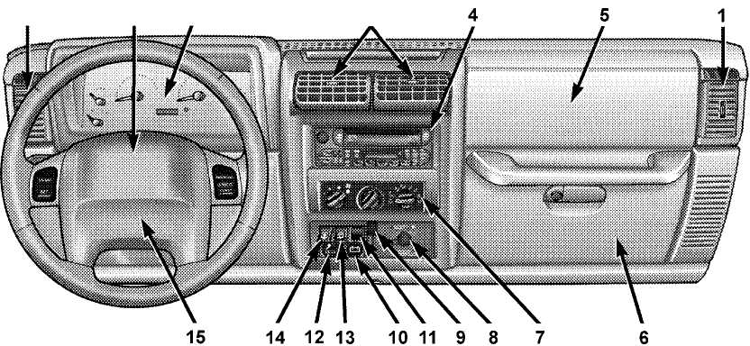
Air Vents
Driver’s Airbag
Instrument Cluster
Radio
Passenger Airbag
Glove Compartment
Climate Controls
Passenger Airbag Switch*
Axle Lock Switch*
Auxilary Power Outlet
Overdrive Switch*
Cigar Lighter*
Rear Window WiperAVasher Switch*
Rear Window Defroster Switch*
Horn
*If Equipped
INSTRUMENT CLUSTER
UNDERSTANDING YOUR INSTRUMENT PANEL 115
116 UNDERSTANDING YOUR INSTRUMENT PANEL
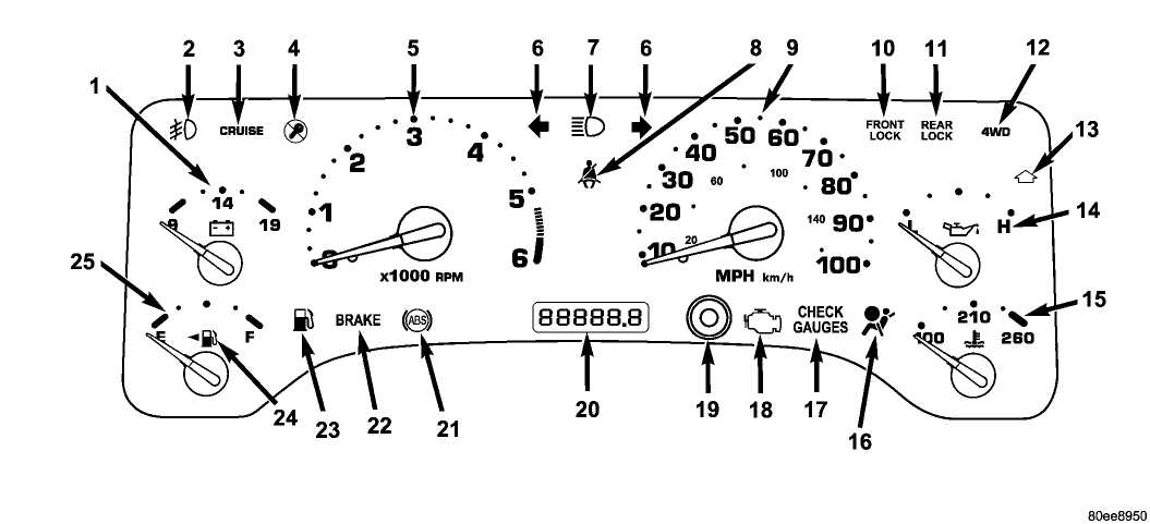
INSTRUMENT CLUSTER DESCRIPTION
Your vehicle is equipped with the instrument cluster described on the following pages.
1. Voltmeter
I- +1 Indicates available battery voltage and charging system operation. The lower red zone indicates that battery charge may be too low to start the engine. With the engine running, the normal operating range is between 11 and 15 volts. Prolonged gauge readings between 8-11 (undercharge) or above 15 (overcharge) indicate possible malfunction of generator, voltage regulator or battery. See your dealer if such indications occur.
2. Front Fog Light Indicator Light — If Equipped
This light shows when the front fog lights are on.
3. Cruise Indicator Light
CRUISE ^*s %nt snows when the electronic speed control system is turned on.
4. Sentry Key Indicator Light — If Equipped
Refer to "Sentry Key Immobilizer System" in Section 2 of this manual.
5. Tachometer
Indicates the engine speed in revolutions per minute (RPM).
CAUTION!
Do not operate the engine with the tachometer pointer in the red area. Engine damage will occur.
6. Turn Signal Indicator Lights
The arrows will flash with the exterior turn sig- nals when the turn signal lever is operated. A tone
will chime if the turn signals are left on for more than
1 mile (2 km).
UNDERSTANDING YOUR INSTRUMENT PANEL 117
7. High Beam Indicator Light
![]() =(""") This light shows that the headlights are on high ~~ beam. Pull the turn signal lever towards the steering wheel to switch the headlights from high or low. If the driver’s door is open, and the headlights or parklights are left on, the "High Beam Indicator Light" will flash and a chime will sound.
=(""") This light shows that the headlights are on high ~~ beam. Pull the turn signal lever towards the steering wheel to switch the headlights from high or low. If the driver’s door is open, and the headlights or parklights are left on, the "High Beam Indicator Light" will flash and a chime will sound.
8. Seat Belt Indicator Light
A warning chime and an indicator light will alert you to buckle the seat belts. When the belt is buckled, the chime will stop, but the light willstay on until it times out (about 6 seconds).
9. Speedometer
Indicates vehicle speed.
10. Front Axle Lock Indicator Light — If Equipped
Indicates when the front axle lock has been FF*ONT activated.
11. Rear Axle Lock Indicator Light — If Equipped
Indicates when the rear axle lock has been
REAR activated. LOCK
12. 4WD Indicator Light
This light alerts the driver that the vehicle is in the four-wheel drive mode, and the front ![]() and rear driveshafts are mechanically lockedtogether forcing the front and rear wheels to rotate at the same speed.
and rear driveshafts are mechanically lockedtogether forcing the front and rear wheels to rotate at the same speed.
13. Shift Indicator Light — If Equipped
![]() This light shows the driver when to shift to the next higher gear for best fuel economy (4.0L Only).
This light shows the driver when to shift to the next higher gear for best fuel economy (4.0L Only).
14.Oil Pressure Gauge
Indicates engine oil pressure. This gauge does ![]() not indicate oil level, and pressure varies with engine speed, temperature and oil viscosity. Consistent lower readings indicate possible malfunction. Seek authorized service.
not indicate oil level, and pressure varies with engine speed, temperature and oil viscosity. Consistent lower readings indicate possible malfunction. Seek authorized service.
118 UNDERSTANDING YOUR INSTRUMENT PANEL
15.Coolant Temperature Gauge
Indicates engine coolant temperature. The red ![]() zone to the far right indicates possible overheating. Seek authorized service immediately if the gauge operates in the red zone. In U.S. vehicles, temperature is indicated in degrees fahrenheit; in Canadian vehicles in degrees centigrade.
zone to the far right indicates possible overheating. Seek authorized service immediately if the gauge operates in the red zone. In U.S. vehicles, temperature is indicated in degrees fahrenheit; in Canadian vehicles in degrees centigrade.
16. Airbag Warning Light
This indicator lights and remains lit for 6 to 8 seconds when the ignition is first turned on. If the light does not come on for 6 to 8seconds, stays on or comes on while driving,
have the airbag system checked by an authorized
dealer.
17. Check Gauges Warning Light
This light monitors the engine coolant tem![]() perature, engine oil pressure, and voltage gauges. If it detects an extreme condition achime will sound and the light will come on. If the light comes on, check the operation of these gauges for a malfunction condition.
perature, engine oil pressure, and voltage gauges. If it detects an extreme condition achime will sound and the light will come on. If the light comes on, check the operation of these gauges for a malfunction condition.
18. Malfunction Indicator Light
This light is a part of an Onboard Diagnostic System called OBD II that monitors engine, ![]() and automatic transmission control systems.The light will illuminate when the ignition is in the ON position before engine start. If the bulb does not come on when turning the key from OFF to ON, have the condition checked promptly.
and automatic transmission control systems.The light will illuminate when the ignition is in the ON position before engine start. If the bulb does not come on when turning the key from OFF to ON, have the condition checked promptly.
Certain conditions such as a loose or missing gas cap, poor quality fuel, etc. may illuminate the light after engine start. The vehicle should be serviced if the light stays on through several typical driving styles. In most situations, the vehicle will drive normally and will not require towing.
When the engine is running, the "Malfunction Indicator Light" may flash to alert serious conditions that could lead to immediate loss of power or severe catalytic converter damage. The vehicle should be serviced as soon as possible if this occurs.
UNDERSTANDING YOUR INSTRUMENT PANEL 119
19. Trip Odometer Button
Press and release this button to toggle between the odometer and trip odometer displays. This button is also used to reset the trip odometer to 0. While the display is showing the trip odometer, press and hold the button for approximately 2 seconds and the display will reset to 0.
20. Odometer/Trip Odometer
The odometer shows the total distance the vehicle has been driven.
The odometer will "illuminate" when the driver’s door has been opened, and will remain on for 20 seconds after exiting the vehicle.
U.S. federal regulations require that upon transfer of vehicle ownership, the seller certify to the purchaser the correct mileage that the vehicle has been driven. Therefore, if the odometer reading is changed during repair or replacement, be sure to keep a record of the reading before and after the service so the correct mileage can be determined.
The trip odometer shows individual mileage up to 999.9 miles (1 600 km). To switch from odometer to trip odometer, press the trip odometer button.
21.Anti-Lock (ABS) Warning Light
After ignition is turned on, illuminates to indi![]() cate function check at vehicle start-up. If light remains on after start-up or comes on and stays on at road speeds, it may indicate that the ABS has detected a malfunction or has become inoperative. The system reverts to standard non-anti-lock brakes.
cate function check at vehicle start-up. If light remains on after start-up or comes on and stays on at road speeds, it may indicate that the ABS has detected a malfunction or has become inoperative. The system reverts to standard non-anti-lock brakes.
If both the red BRAKE warning light and the amber ABS warning light are on, see your dealer immediately. Refer to "Anti-Lock Brake System" in Section 5 of this manual.
22. Brake Warning Light
After ignition is turned on, illuminates to in![]() dicate function check at vehicle start-up. Indicates parking brake is applied. If the light stays on when the parking brake is off, it indicates a possible brake system fluid leak or low pressure level, see your authorized dealer immediately.
dicate function check at vehicle start-up. Indicates parking brake is applied. If the light stays on when the parking brake is off, it indicates a possible brake system fluid leak or low pressure level, see your authorized dealer immediately.
120 UNDERSTANDING YOUR INSTRUMENT PANEL
If the parking brake is applied and the vehicle is in motion, the red BRAKE warning light will "flash" and a chime will sound.
The operation of the BRAKE warning light can be checked by turning the ignition switch from the OFF position to the ON position. The light should illuminate for approximately two seconds. The light should then turn off unless the parking brake is applied or a brake fault is detected. If the light does not illuminate, have the light inspected by an authorized dealer.
23.Low Fuel Warning Light
When the fuel level reaches approximately 2 U.S. ![]() Gallons (7.6L) this light will come on and remain on until fuel is added. The "Low Fuel Warning Light" may turn on and off again, especially during and after hard braking, accelerations, or turns. This occurs due to the shifting of the fuel in the tank.
Gallons (7.6L) this light will come on and remain on until fuel is added. The "Low Fuel Warning Light" may turn on and off again, especially during and after hard braking, accelerations, or turns. This occurs due to the shifting of the fuel in the tank.
24. Fuel Cap Indicator
This symbol indicates the side of the vehicle where the fuel cap is located.
25. Fuel Gauge
The pointer shows the level of fuel in the fuel tank. When the fuel gauge pointer initially moves to E, for your safety, approximately 2 U.S. Gallons (7.6L) of fuel remain.
NOTE: When the ignition switch is turned to OFF, the fuel gauge, voltmeter, oil pressure and temperature gauges may not show accurate readings. When the engine is not running, turn the ignition switch to ON to obtain accurate readings.
ELECTRONIC DIGITAL CLOCK
The clock and radio each use the display panel built into the radio. A digital readout shows the time in hours and minutes whenever the ignition switch is in the ON or ACC position and the time button is pressed.
When the ignition switch is in the OFF position, or when the radio frequency is being displayed, time keeping is accurately maintained.
UNDERSTANDING YOUR INSTRUMENT PANEL
Clock Setting Procedure
Turn the ignition switch to the ON or ACC position
and press the time button. Using the tip of a ballpoint pen
or similar object, press either the hour (H) or minute (M)
buttons on the radio.
Press the H button to set hours or the M button to set
minutes. The time setting will increase each time you
press a button.
RADIO GENERAL INFORMATION
Radio Broadcast Signals
Your new radio will provide excellent reception under most operating conditions. Like any system, however, car radios have performance limitations, due to mobile operation and natural phenomena, which might lead you to believe your sound system is malfunctioning. To help you understand and save you concern about these "apparent" malfunctions, you must understand a point or two about the transmission and reception of radio signals.
Two Types of Signals
There are two basic types of radio signals... AM or Amplitude Modulation, in which the transmitted sound causes the amplitude, or height, of the radio waves to vary... and FM or Frequency Modulation, in which the frequency of the wave is varied to carry the sound.
Electrical Disturbances
Radio waves may pick up electrical disturbances during transmission. They mainly affect the wave amplitude, and thus remain a part of the AM reception. They interfere very little with the frequency variations that carry the FM signal.
AM Reception
AM sound is based on wave amplitude, so AM reception can be disrupted by such things as lightning, power lines and neon signs.
FM Reception
Because FM transmission is based on frequency variations, interference that consists of amplitude variations can be filtered out, leaving the reception relatively clear, which is the major feature of FM radio.
UNDERSTANDING YOUR INSTRUMENT PANEL
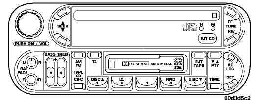
SALES CODE RAD—AM & FM STEREO RADIO WITH GRAPHIC EQUALIZER, CASSETTE TAPE PLAYER WITH CD PLAYER
Radio Security Code
This radio is equipped with an anti-theft feature which requires that a four digit code number be entered whenever the power supply is interrupted (such as a disconnected battery). The four digit code can be found on the last page of this manual. Please remove this page from the manual and store it in a safe place outside of the vehicle.
To enter the code, turn the key to the ON or ACC position and press the ON/VOL control. The word CODE will appear on the display. Enter your four digit code by pressing the appropriate preset buttons in sequence. Your radio is now ready for basic operation.
If an invalid code is entered into the radio, the radio will allow two more attempts. After a third attempt of entering an invalid code, the radio will go into a lockup mode. This is to prevent continuous attempts at entering the wrong code until the right code is found.
Once a radio is in this lockup mode, it must be in a state where battery is applied for approximately 30 minutes. During this time, if the radio is on, the display will show "WAIT". After approximately 30 minutes, (radio on) radio will display "CODE" thereby again querying the operator for the 4 digit anti-theft code.
Operating Instructions - Radio Mode
NOTE: Power to operate the radio is supplied through the ignition switch. It must be in the ON or ACC position to operate the radio.
UNDERSTANDING YOUR INSTRUMENT PANEL
Power Switch, Volume Control
Press the ON/VOL control to turn the radio on. Turn the volume control to the right to increase the volume.
Seek Button (Radio Mode)
Press and release the Seek button to search for the next station in either the MW/LW or FM mode. Press the top of the button to seek up and the bottom to seek down. The radio will remain tuned to the new station until you make another selection. Holding the button in will bypass stations without stopping until you release it.
Tuning
Press the TUNE control up or down to increase or decrease the frequency. If you press and hold the button, the radio will continue to tune until you release the button. The frequency will be displayed and continuously updated while the button is pressed.
Balance
The Balance control adjusts the left-to-right speaker balance. Push in the button and it will pop out. Adjust the balance and push the button back in.
Fade
The Fade control provides for balance between the front and rear speakers. Push in the button and it will pop out. Adjust the balance and push the button back in.
Tone Control
Slide the Bass and/or Treble controls up or down to adjust the sound for the desired tone.
AM/FM-TAPE/CD/CD-C
Press the top of this button to switch between MW, FM, and LW. Press the bottom of this button to switch between Tape, CD, and optional CD changer control operation.
To Set The Radio Push-button Memory
You can store a total of 10 FM, 5 MW and 5 LW stations into memory.
When you are receiving a FM station that you wish to commit to push-button memory, press the SET button. SET 1 will appear in the radio display window. Select the push button you wish to lock on this station and press and release that button. If a button is not selected within