Ā
1993 Jeep Cherokee
1993 Drive Axles - Front Axles
Cherokee, Grand Cherokee, Grand Wagoneer, Wrangler
DESCRIPTION
Model 30 axle is used on all 4WD applications. Cherokee uses Selec-Trac 4WD system. Wrangler uses Command-Trac 4WD system. Grand Cherokee and Grand Wagoneer use a full-time 4WD system.
Command-Trac is a part-time system designed for off-road use. Command-Trac uses a vacuum operated axle disconnect mechanism to control 4WD operation.
Selec-Trac is a combination part-time/full-time system designed for both highway and off-road use. Transfer case shifter is used to control 4WD operation.
AXLE RATIO & IDENTIFICATION
Axle build date and manufacturerÆs number are stamped on passenger-side axle tube, near housing cover. Axle assembly part number, gear ratio and identification tag are attached to the left side of the housing cover. See AXLE RATIO & IDENTIFICATION table.
AXLE RATIO & IDENTIFICATION TABLE
Axle Pinion/Ring Gear Ring Gear
Ratio Tooth Combinations Diameter
Front Axle (1)
3.07:1 14/43 7 1/8" (181 mm)
3.55:1 11/39 7 1/8" (181 mm)
4.10:1 9/37 7 1/8" (181 mm)
(1) - Model 30 axle used on all models.
REMOVAL & INSTALLATION
NOTE: This article covers removal, installation and overhaul of
front axle components. For information on differential, see 7 1/8", 7 9/16" & 8 1/4" RING GEARS article.
AXLE ASSEMBLY
Removal (Except Wrangler)
Raise and support vehicle under frame. Remove wheels.
Remove disc brake calipers. Hang calipers aside with wire. Remove
rotors and brake shields.
Disconnect breather tube at axle. Remove vent hose from
differential housing. Remove stabilizer bar link, tie rod and drag
link. Remove front drive shaft. Disconnect shock absorbers and
steering damper. If equipped with Anti-Lock Brake System (ABS),
disconnect brake sensor.
Disconnect track bar. Position jack under axle. Disconnect
upper and lower control arms at axle. Lower and remove axle slowly to
release coil spring pressure.
Installation (Except Wrangler)
Raise axle into position while guiding coil springs into position. Connect upper and lower control arms to axle. To complete installation, reverse removal procedure.
Removal (Wrangler)
Raise vehicle. Position supports under frame rails at rear
of front springs. Remove wheels. Remove brake calipers and hang aside
with wire. Remove brake rotors. Disconnect Command-Trac vacuum
harness.
Mark front drive shaft and axle yoke for reassembly.
Disconnect front drive shaft at axle yoke. Secure shaft to frame with
wire. Disconnect tie rods at steering knuckles. Remove steering
damper. Remove shock absorbers. Remove retaining nuts and bolts from
track bars at axle shaft tube brackets. Disconnect breather tube at
axle. Disconnect stabilizer bar link bolts at spring brackets.
Support axle and raise jack slightly to relieve spring
tension. Remove spring "U" bolts and brackets. Loosen nuts attaching
spring rear shackles to springs. Remove bolts attaching spring front
shackles. Lower springs to floor. Remove axle assembly.
Installation (Wrangler)
To install, reverse removal procedure.
AXLE SHAFT
Removal
Raise and support vehicle. Remove wheels, caliper and
rotor. Remove cotter pin, lock nut and axle hub nut.
Remove hub-to-steering knuckle bolts. Remove hub and rotor
shield from steering knuckle. Remove left axle shaft from axle tube.
On models with Command-Trac, disconnect vacuum harness. Remove vacuum
motor housing. See Fig. 1.
Remove right axle shaft from axle tube. Ensure shift
collar remains on intermediate shaft.
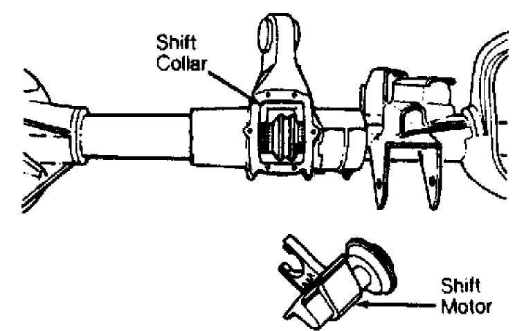
Fig. 1: Removing Command-Trac Shift Motor Courtesy of Chrysler Corp.
Installation
1) Install right and left axle shafts in axle tubes. On
models with Command-Trac, ensure shift collar is correctly positioned on intermediate axle shaft.
Ensure outer axle shaft is completely engaged with shift
collar and joined with intermediate axle shaft. See Fig. 1. Install
shift motor. Ensure fork engages with shaft collar.
On all models, lubricate hub bore in steering knuckle with
wheel bearing grease. Install rotor shield. Install hub on axle. Slide
hub into steering knuckle hub bore. Tighten hub bolts. Install the
washer and the hub nut. Tighten hub nut to proper specification. See
TORQUE SPECIFICATIONS TABLE at the end of this article. Install
retainer and cotter pin. Install rotor, caliper and wheel. Lower
vehicle.
INTERMEDIATE AXLE SHAFT
Removal & Installation (Wrangler)
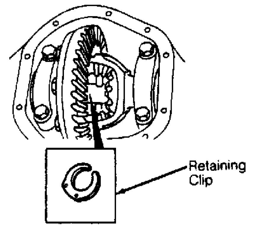
Fig. 2: Removing Intermediate Shaft Retaining Clip Courtesy of Chrysler Corp.
HUB & BEARING
Remove outer axle. Remove differential cover and drain fluid. Remove intermediate shaft retaining clip. See Fig. 2. Remove intermediate shaft. To install, reverse removal procedure. Fill differential housing with 2.5 pts. (1.2L) of SAE 75W-90 gear oil.
Removal
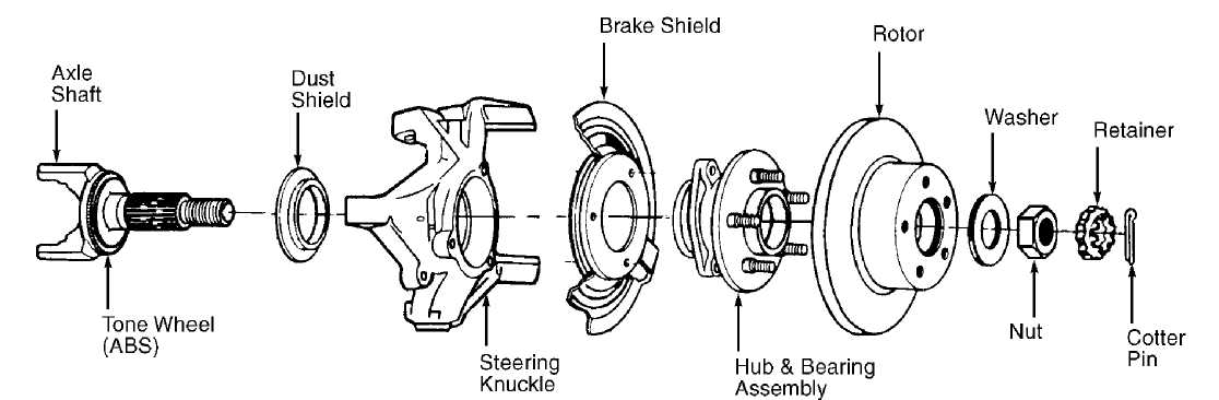
Raise and support vehicle. Remove wheel, caliper and rotor. Remove cotter pin, nut retainer, hub nut and washer. Remove hub-to-knuckle bolts. Remove hub from steering knuckle. See Fig. 3.
Installation
Apply wheel bearing grease to hub bore in steering knuckle and install hub and bearings. To complete installation, reverse removal procedure.
NOTE:
Hub bearings cannot be serviced. If defective, replace complete hub assembly.
92D21835
Fig. 3: Exploded View Of Hub Assembly Courtesy of Chrysler Corp.
OVERHAUL
AXLE SHAFT OUTER "U" JOINT
Remove axle shaft. Remove bearing cap and snap rings. Press out bearings caps from yoke. To install, reverse removal procedure. Pack replacement bearing caps 1/3 full of bearing grease.
AXLE SHAFT CV JOINT
NOTE: If worn or damaged, assembly.
CV joint MUST be replaced as a complete
Disassembly
Remove boot clamps. Carefully slide boot down axle shaft.
Remove lubricant to expose CV joint components. Place joint in soft-
jawed vise. Remove internal circlip and slide CV joint from shaft.
Using paint, mark hub, bearing cage and housing for reassembly
reference.
Press down on one side of bearing cage to access bearing
balls. If CV joint is tight, use a hammer and brass drift to loosen
hub. DO NOT strike cage or ball. Remove balls. Remove hub and cage
from housing. Align hub lands with cage windows. Rotate hub 90 degrees
and remove hub from cage. Inspect components for wear and damage.
Replace joint, if necessary.
marks.
Reassembly
1) Lightly oil components before reassembly. Align reference Install hub into cage. Install hub/cage into housing. Tilt cage
and insert balls into hub raceways. Push high side of hub/cage assembly into housing. Ensure assembly rotates freely in housing. Install shaft and circlip.
2) Pack bearing assembly with molybdenum base CV joint
grease. Slide boot over CV joint. Install NEW boot clamps. Check shaft and joint for smooth movement.
TORQUE SPECIFICATIONS
TORQUE SPECIFICATIONS TABLE
Applications
Ft. Lbs. (N.m)
Cherokee
Axle Yoke Nut 210 (285)
Hub Bolt 75 (102)
Hub Nut 175 (237)
Lower Control Arm Bolt 85 (115)
Track Bar Axle Bracket Nut 74 (100)
Track Bar Frame Nut 31 (42)
"U" Joint Strap Bolt 14 (19)
Upper Control Arm Bolt 55 (75)
Grand Cherokee & Grand Wagoneer
Hub Bolt 75 (102)
Hub Nut 175 (237)
Spring Pivot Bolt 100 (136)
Track Bar Axle Bracket Nut 74 (100)
Track Bar Ball Stud Nut 60 (81)
Upper Control Arm Bolt 55 (75)
Wrangler
Axle Yoke Nut 210 (285)
Frame Bracket 105 (142)
Hub Bolt 75 (102)
Hub Nut 175 (237)
Shackle Bolt 95 (129)
Track Bar Axle Nut 74 (100)
Track Bar Frame Nut/Bolt 125 (169)
"U" Bolt At Axle Tube Retaining Nut 90 (122)
"U" Joint Strap Bolt 14 (19)
INCH Lbs. (N.m)
Vacuum Shift Motor Bolt 98 (11)