THEORY/OPERATION - 2.5L & 4.0L
1993 Jeep Cherokee
1993 ENGINE PERFORMANCE
Chrysler Corp. Theory & Operation
Jeep; Cherokee, Grand Cherokee, Wrangler
INTRODUCTION
This article covers basic description and operation of engine performance-related systems and components. Read this article before diagnosing vehicles or systems with which you are not completely familiar.
COMPUTERIZED ENGINE CONTROLS
POWERTRAIN CONTROL MODULE (PCM)
The Powertrain Control Module (PCM) is a dual microprocessor that receives various signals from engine sensors and provides the necessary signals to control engine sub-systems. The PCM has a voltage converter that converts battery voltage to regulated 5-volt or 8-volt outputs. The regulated 5-volt output is used to power Manifold Absolute Pressure (MAP) sensor, Throttle Position Sensor (TPS) and logic circuits. The regulated 8-volt output is used to power crankshaft position sensor and camshaft position sensor in distributor.
The ignition and fuel injection systems are controlled by the PCM. Based on present engine operating conditions, the PCM is programmed to provide a precise amount of fuel and the correct ignition timing to meet existing engine speed and load requirements.
The PCM adjusts ignition timing based on inputs it receives from camshaft position sensor, MAP sensor, coolant temperature sensor, throttle position sensor, vehicle speed sensor, transmission gear selection (automatic transmissions only) and brake switch.
The PCM adjusts idle speed based on inputs it receives from throttle position sensor, vehicle speed sensor, transmission gear selection (automatic transmissions only), A/C clutch switch and brake switch.
The PCM also controls the speed (cruise) control system and alternator charge rate by controlling the alternator field.
NOTE: Components are grouped into 2 categories. The first category covers INPUT DEVICES, which control or produce voltage signals that are monitored by the PCM. The second category covers OUTPUT SIGNALS, which are components controlled by the PCM.
INPUT DEVICES
Vehicles are equipped with different combinations of input devices. Not all devices are used on all models. To determine the input device usage on a specific model, see appropriate wiring diagram in L - WIRING DIAGRAMS article in the ENGINE PERFORMANCE Section. The available input signals include the following:
A/C Pressure Switch & Evaporator Switch
When A/C switch is in ON position and A/C low pressure switch and evaporator switch are closed, an A/C select signal is sent to PCM. If A/C low pressure switch or evaporator switch opens, the PCM will
not receive an A/C select signal.
When A/C function is selected (A/C switch on), the A/C request signal provides information to the PCM from the A/C temperature control thermostat (evaporator switch). This signal indicates evaporator temperature is in the proper range for A/C operation.
The A/C request signal is used by PCM to determine required Idle Air Control (IAC) motor position and to activate or deactivate A/C compressor clutch. When PCM receives an A/C request signal, it repositions the IAC motor to increase idle speed. The increased idle speed compensates for additional engine load caused by engagement of A/C compressor.
On 4.0L, whenever A/C compressor clutch is energized, PCM also energizes the radiator (cooling) fan relay. This occurs regardless on engine coolant temperature.
Alternator Output
The PCM keeps charging system voltage at 13.5-14.8 volts. Charging system voltage will be adjusted by PCM based on battery temperature sensor, located within PCM housing. The voltage determined by PCM as final goal for charging system is called "control" voltage. The control voltage will be used to determine alternator field control and to detect if charging system is operating properly.
If sensed voltage is lower than "control" voltage, PCM will alter duty cycle and ground alternator (rotor) field for a longer period of time and create a higher alternator output which should raise sensed voltage level. If sensed voltage is higher than "control" voltage, PCM will alter duty cycle and lower alternator output which should lower sensed voltage level.
Battery Voltage Signal
The PCM uses battery voltage level to regulate alternator field (rotor) duty cycle and alter fuel injector pulse width according to available voltage. If battery voltage drops, PCM will increase injector on time to compensate for the reduced fuel flow of injector caused by the lower voltage. This will permit injector to deliver proper amount of fuel to the engine.
Brake Switch
The brake switch is mounted on steering column support bracket, under instrument panel. The PCM uses the brake switch to determine when brakes are applied. When brakes are applied (brake switch on) and if PCM sees a TPS opening and a lower speed sensor rate, it recognizes a deceleration condition and opens up the Idle Air Control (IAC) motor. The brake switch signal will also disengage speed (cruise) control operation, if it was engaged.
Coolant Temperature Sensor
The coolant temperature sensor is mounted on top of engine, next to thermostat housing. It provides an analog signal to the PCM that is used to calculate injector pulse width and ignition timing when engine is cold. Input from the coolant temperature sensor will also affect Idle Air Control (IAC) motor position and spark advance operation.
Crankshaft Position Sensor
The Hall Effect type crankshaft position sensor is mounted on transaxle bellhousing. The sensor reads slots (4 per cylinder) on flywheel/flex plate. The signal generated provides engine speed and crankshaft position information to PCM. The PCM uses this information to determine proper fuel injection and ignition timing.
When a flywheel/flex plate slot passes the crankshaft position sensor magnet, output voltage of the Hall Effect sensor goes
high (5 volts). When the metal between the slots is aligned with sensor, output voltage goes low (.3 volts).
This high/low voltage signal is sent to PCM each time one of the slots passes the crankshaft position sensor. The PCM uses this information to determine when to energize the injectors for fuel delivery to the proper cylinders.
Ignition Circuit
When ignition switch is turned to the ON position, the PCM receives a signal that the ignition circuit has been activated. The PCM will start monitoring input signals.
Manifold Absolute Pressure (MAP) Sensor
The MAP sensor is mounted on engine compartment firewall. The MAP sensor is used by PCM to calibrate amount of air/fuel mixture supplied to the engine. This sensor measures manifold absolute pressure. Ambient barometric pressure is also measured when ignition switch is first turned on, during engine cranking, and at wide open throttle.
The MAP sensor transmits a low voltage signal (1.5-2.1 volts) at idle when manifold vacuum is high, and a higher voltage signal (3. 9-4.8 volts) during open throttle when manifold vacuum is low.
Input voltage (from the PCM) to MAP sensor ranges from 4.8-5. 1 volts. Adjustments made as a result of this input will usually affect injector pulse width, ignition timing, idle speed and upshift indicator light.
Manifold Air Temperature (MAT) Sensor
The MAT sensor is located on intake manifold, with sensor element extending into the air stream. The sensor measures the temperature of air entering the intake manifold. This sensor provides an analog voltage signal to PCM. This signal is used to compensate for changes in air density due to temperature.
The MAT sensor is a Negative Temperature Coefficient (NTC) thermistor-type sensor. Its internal resistance varies opposite with temperature. At cold temperatures, the resistance is high. As temperature increases, its resistance decreases.
Oxygen (O2) Sensor
The heated oxygen sensor detects amount of oxygen content of the exhaust gases and produces a voltage signal. PCM uses this signal to determine system output signals which control air/fuel mixture.
Variations in voltage signal from O2 sensor serve as air/fuel ratio indicators. When oxygen content is low (rich mixture), voltage signal will be approximately one volt. When oxygen content is high (lean mixture), voltage signal will be approximately 0.1 volt.
The O2 sensor contains a ceramic heater in the sensor housing. The heater operates on 12 volts. The heater is used in cold starts to help O2 sensor heat up quicker and to maintain the O2 sensorÆs Zirconia semiconductor at operating temperature.
In "closed loop" operation, PCM monitors O2 sensor input (along with other sensors) and adjusts the injector pulse width accordingly. During "open loop" operation (cold oxygen sensor), PCM ignores O2 sensor input and adjusts injector pulse width to a pre┬Łprogrammed value based on other sensor inputs.
Park/Neutral Switch
On vehicles equipped with automatic transmission, a gear position indicator signal is sent to the PCM when gear selector lever has been moved to the Drive range. This signal comes from the park/neutral switch (neutral safety switch on AW-4 transmission) and allows the PCM to adjust idle speed, fuel injector pulse width, and ignition timing advance.
Power Steering Switch
On 2 . 5L with power steering, a power steering switch is used. The switch is located on pressure line, next to power steering pump.
The power steering switch sends a signal to PCM when system pressure rises to greater than 250-300 psi (17.6-21.1 kg/cm) when engine RPM is low. The PCM, through IAC motor, will then increase idle speed to prevent engine stalling.
Serial Communications Interface Receive
The Serial Communications Interface (SCI) receive circuit is the serial data circuit that is used when diagnosing vehicle with ChryslerÆs Diagnostic Readout Box-II (DRB-II). The PCM receives data from the DRB-II through this SCI receive circuit.
Speed (Cruise) Control Switches
The speed (cruise) control switches provide 3 separate inputs to the PCM. The ON/OFF switch informs PCM that speed control system has been activated. The SET switch informs PCM that a set vehicle speed has been selected. The RESUME switch informs PCM that the previously selected set speed has been selected.
Start (Cranking) Signal
The start (cranking) signal from starter relay signals PCM when starter is engaged. When PCM determines starter is engaged, it begins to monitor inputs from crankshaft position sensor and camshaft position sensor.
The PCM uses these signals to determine spark timing and whether the first fuel injection should occur at cylinder No. 4 or 1 (4-cylinder) or cylinder No. 3 or 4 (6-cylinder). Once synchronization has been established, the PCM energizes the proper injector and provides the ignition output needed to start the engine.
Camshaft Position Sensor
The camshaft position sensor is located in distributor. This Hall Effect type sensor works in conjunction with engine speed signal of crankshaft position sensor providing PCM with inputs necessary to establish and maintain proper fuel injector firing order.
When leading edge of pulse ring enters the sync signal
generator on the camshaft position sensor, the resulting change in the magnetic field causes a 5-volt reference signal to be induced. On 4-cylinder engines, this indicates to the PCM that piston No. 4 will be the next piston at Top Dead Center (TDC). On 6-cylinder engine, it indicates that piston No. 3 will be at TDC.
When trailing edge of pulse ring leaves the sync signal generator on the camshaft position sensor, the resulting collapse of the magnetic field causes reference signal to drop to zero volts. On 4-cylinder engines, this indicates that piston No. 1 will be the next piston at TDC. On 6-cylinder engine, it indicates that piston No. 4 will be at TDC.
Throttle Position Sensor (TPS)
The TPS is mounted on throttle body and monitors opening angle of throttle valve. It contains a potentiometer operated by the opening and closing of throttle plate. PCM uses TPS input signal to determine throttle position under all operating conditions and adjust fuel injector pulse width and ignition timing accordingly.
The PCM supplies a 5-volt reference signal to TPS. The TPS output voltage (input signal to PCM) represents throttle blade position. The TPS output voltage varies from one volt at minimum throttle opening (idle) to 4 volts at wide open throttle.
Vehicle Speed Sensor
The vehicle speed sensor is located on transaxle extension housing (2WD models) or on transfer case extension housing (4WD models). The PCM uses vehicle speed (distance) sensor to detect if vehicle is moving and at what speed it is moving.
The sensor is an 8-pole switch which provides a pulse or switching rate, proportional to vehicle speed, to the PCM. By comparing the number of pulses to time elapsed, the PCM determines vehicle speed and distance traveled.
The vehicle speed sensor generates 8 pulses per sensor revolution. This signal, along with a closed throttle signal from the TPS sensor, indicates a closed throttle deceleration to the PCM.
Under deceleration conditions, PCM adjusts the Idle Air Control (IAC) motor to maintain desired MAP value. During idle (vehicle stopped), the PCM adjusts the IAC motor to maintain a desired engine speed.
The vehicle speed (distance) sensor input is used to maintain speed (cruise) control operation and also as a reference for Service Reminder Indicator (SRI) light.
Vehicle Theft Alarm (Cherokee)
Vehicle theft alarm module provides a signal to PCM to enable it to start the engine. With theft alarm module activated, no signal through the communication bus will be sensed by the PCM and the engine will not start. The PCM controls ignition and fuel delivery to the engine.
OUTPUT SIGNALS
NOTE: Vehicles are equipped with different combinations of
computer-controlled components. Not all components listed below are used on every vehicle. For theory and operation on each output component, refer to the system indicated after component.
A/C Compressor Clutch Relay See MISCELLANEOUS CONTROLS.
Alternator Light
See MISCELLANEOUS CONTROLS.
Automatic Shutdown Relay See FUEL DELIVERY.
Ballast Resistor See FUEL DELIVERY.
Ballast Resistor By-Pass Relay See FUEL DELIVERY.
Fuel Injectors See FUEL CONTROL.
Fuel Pump Relay See FUEL DELIVERY.
Idle Air Control (IAC) Motor See IDLE SPEED.
Ignition Coil
See IGNITION SYSTEM.
Injection Timing See FUEL CONTROL.
Malfunction Indicator Light (MIL) See SELF-DIAGNOSTIC SYSTEM.
Radiator (Cooling) Fan Relay See MISCELLANEOUS CONTROLS.
Serial Communication Interface Transmit See MISCELLANEOUS CONTROLS.
Service Reminder Indicator (SRI) See EMISSION SYSTEMS.
Speed (Cruise) Control Solenoids See MISCELLANEOUS CONTROLS.
Upshift Indicator Light See MISCELLANEOUS CONTROLS.
FUEL SYSTEM
FUEL DELIVERY
Automatic Shutdown Relay
The Automatic Shutdown (ASD) relay is located in power distribution center near the battery or next to radiator coolant recovery bottle.
The ASD relay is used by the PCM to supply voltage to fuel pump, fuel injectors and ignition coil. The relay contacts are normally open.
Power is supplied to relay coil when the ignition switch is turned on. The PCM controls the ground circuit, which energizes the coil and closes the relay contacts.
The PCM will only ground the relay when ignition switch is in the RUN or START positions and activity is sensed through the crankshaft position sensor and the camshaft position sensor in the distributor. If the PCM senses the RPM signal has stopped, it will remove the ground from relay coil, which will cause the contacts to open and remove power from the circuit.
Ballast Resistor (Cherokee)
A ballast resistor, located between fuel pump relay and the fuel pump, is used to reduce voltage to the fuel pump. This reduces fuel pump noise during operation. Ballast resistor is mounted on fender panel, next to washer fluid reservoir.
When fuel pump relay is energized, voltage is supplied to fuel pump through the ballast resistor. During start and wide open throttle conditions, ballast resistor is by-passed and fuel pump receives its voltage from ballast resistor by-pass relay.
NOTE: Wrangler DOES NOT use a ballast resistor or ballast resistor by-pass relay in the fuel pump circuit. The PCM operates fuel pump through the fuel pump relay during all operating conditions.
Ballast Resistor By-Pass Relay (Cherokee)
A ballast resistor by-pass relay is located on a bracket next to power distribution center (next to coolant recovery bottle). By switching the ground circuit on or off, the PCM can control fuel pump (power) feed. The ballast resistor by-pass relay receives its voltage from fuel pump relay.
Normally, voltage is supplied to fuel pump through a ballast
resistor. At wide open throttle, fuel pump receives voltage through the ballast resistor by-pass relay, which speeds up fuel pump to compensate for higher fuel demand.
Fuel Pump (Electric)
All models are equipped with a gear/rotor type electric pump. Pump is driven by a permanent magnet, 12-volt electric motor. The in-tank pump is an integral part of the fuel gauge sending unit.
Fuel system pressure is maintained at about 31 psi (2.2 kg/cm) when pump is operating and vacuum is applied to fuel pressure regulator. With no vacuum applied to fuel pressure regulator, fuel pressure should be 39-41 psi (2.7-2.9 kg/cm) or higher. When fuel pump is not operating, fuel pressure is maintained at 19-39 psi (1.3-2.7 kg/cm) by fuel pump outlet check valve and the fuel pressure regulator.
Fuel Pump Relay
On Cherokee, fuel pump relay is located in the power
distribution center, next to coolant recovery bottle. On Wrangler and Grand Cherokee, the fuel pump relay is located in the power distribution center next to battery.
The feed side of the relay coil is powered by the ignition switch. The relay is energized by the PCM by grounding the other side of the relay coil. The relay contacts are normally open and will close when the PCM provides a ground path for the relay coil.
The fuel pump circuit is completed during cranking and whenever the engine is running. If the ignition switch is turned to the RUN position, the fuel pump will operate for 1-3 seconds and then shut off. If the PCM does not receive a crank or run signal, it deactivates the fuel pump by opening the relay coil ground circuit. The 1-3 second time limit is used to prevent unnecessary operation of the fuel pump once the system is pressurized. If the engine were running, the PCM would maintain the fuel pump relay coil ground allowing continuous operation of the fuel pump.
FUEL CONTROL
Fuel Injectors
The fuel injectors are controlled electronically by the PCM. Because each injector is connected to 12 volts, the injector is energized when connected to ground through the PCM. The PCM also controls the amount of time the injector is energized (pulse width). Pulse width is based on various inputs and is calculated by the PCM. The fuel injectors are sequentially energized (in firing order) by the PCM.
With injector connected to a pressurized fuel supply, a fine mist will spray from the injector nozzle into the intake manifold. The injector uses an electromagnet and spring pressure to open or close the fuel metering plunger. When connected to battery voltage, the coil of wire in the injector becomes an electromagnet. The magnetic field generated will overcome spring pressure and raise the plunger off its seat. When the injector circuit is opened by the PCM, the magnetic field collapses and spring pressure forces the plunger against its seat.
Whenever an injector is opened, it will always spray a consistent amount of fuel for a given amount of pressure. Because pressure drop across the injector is fixed and the fuel flow rate constant, the only control variable is the amount of time injector is open. By controlling the time the injector is open (pulse width), the PCM can decrease pulse width for engine idle or it can increase pulse width at wide open throttle.
Injection Timing
All engines use a sequential port fuel injection system. This means that the injectors have a specific firing order and fuel injection is timed to piston movement. The spark plugs and injectors are fired in the same order: 1-3-4-2 on 2.5L and 1-5-3-6-2-4 on 4.0L.
In order for the PCM to fire the injectors in a specific order timed to crankshaft and piston movement, it has to establish a reference point. Establishing the reference point requires PCM inputs from the crankshaft position sensor and camshaft position sensor.
The crankshaft position sensor is located on transmission bellhousing and provides the PCM with crankshaft angle and speed. The PCM converts crankshaft speed into engine RPM and crankshaft angle into piston position.
On 2.5L engine, the slotted flywheel/drive plate, rotating past the sensor, contains 2 groups of 4 slots located 180 degrees apart. Each group of slots represents the position of 2 of the pistons. Pistons No. 1 and 4 approach TDC at the same time and use the same flywheel slot, while piston No. 3 is matched with piston No. 2.
On 4.0L engine, the slotted flywheel/drive plate, rotating past the sensor, contains 3 groups of 4 slots located 120 degrees apart. Each group of slots represents the position of 2 of the pistons. Pistons No. 1 and 6 approach TDC at the same time and use the same flywheel slot. Pistons No. 2 and 5 are matched, while piston No. 3 is matched with piston No. 4.
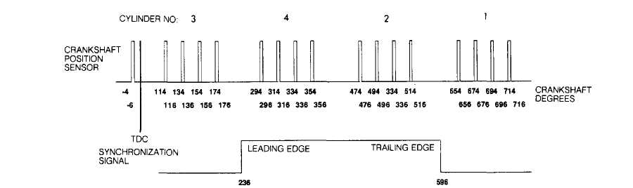
2 5L 4-CYLINDER INJECTION TIMING SCHEMATIC
The PCM, through the crankshaft position sensor, knows that 2 pistons are approaching TDC and uses the sync signal generator on the camshaft position sensor to determine which injector/spark plug to fire. See Fig. 1.
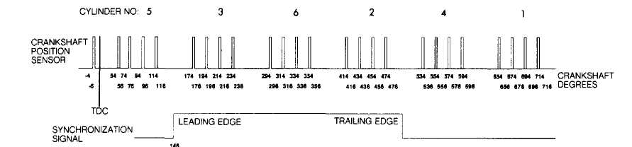
4.0L 6-CYLINDER INJECTION TIMING SCHEMATIC
Fig. 1: Sequential Port Fuel Injection (SPFI) Timing
IDLE SPEED
Idle Air Control (IAC) Motor
The IAC motor is mounted on throttle body and is used by the PCM to adjust engine idle speed. The throttle plate regulates off-idle
engine speed by controlling the amount of air allowed to enter the intake manifold and is mechanically operated by the accelerator cable.
The PCM and IAC motor adjust engine idle by regulating the size of an air by-pass passage that routes air past the closed throttle plate. The amount of air flowing through the by-pass circuit depends on engine operating conditions at idle.
When the engine is cold, the PCM increases engine speed by retracting the IAC motor pintle, thus allowing more air to enter the intake manifold. To maintain the proper air/fuel mixture, more fuel is also injected into the intake manifold. The increased air/fuel mixture, in turn, raises the engine idle speed. As the engine warms, the PCM will extend the motor pintle into the air passage to reduce the amount of air by-passing the throttle plate.
IGNITION SYSTEM
POWERTRAIN CONTROL MODULE (PCM) CONTROLLED IGNITION SYSTEM
All engines use a Powertrain Control Module (PCM) based ignition system. Base ignition timing is NOT adjustable with this system. The PCM controlled ignition system consists of coolant temperature sensor, crankshaft position sensor, distributor (includes rotor and camshaft position sensor), ignition coil, manifold absolute pressure sensor, PCM and throttle position sensor.
Coolant Temperature Sensor See INPUT DEVICES.
Crankshaft Position Sensor See INPUT DEVICES.
Distributor
Distributor consists of cap, rotor, and camshaft position sensor. The distributor does not use centrifugal or vacuum advance mechanisms to advance ignition timing. Ignition timing advance is electronically controlled by the PCM. See CAMSHAFT POSITION SENSOR under INPUT DEVICES.
Ignition Coil
The ignition coil is constructed of epoxy-embedded windings and is not oil filled. Battery voltage is supplied to the ignition coil positive terminal. The PCM receives inputs from the appropriate sensors. Based on these inputs, it then determines the proper ignition timing and interrupts the ignition coil ground signal to trigger secondary voltage of the ignition coil.
Manifold Absolute Pressure Sensor See INPUT DEVICES.
Manifold Air Temperature Sensor See INPUT DEVICES.
Powertrain Control Module (PCM)
The PCM opens and closes the ignition coil ground circuit to adjust ignition timing according to engine operating conditions. The amount of electronic spark advance provided by the PCM is determined by coolant temperature sensor, crankshaft position sensor (engine RPM), manifold absolute pressure sensor and throttle position sensor inputs. See COMPUTERIZED ENGINE CONTROLS for additional information.
Throttle Position Sensor See INPUT DEVICES.
EMISSION SYSTEMS
CRANKCASE VENTILATION (CCV) SYSTEM
Engines on all models use a crankcase ventilation system. The CCV system performs the same function as a conventional PCV system, but does not use a vacuum controlled valve. On 2.5L engine, a fitting on the driverÆs side of the cylinder head cover contains a metered orifice that is connected to manifold vacuum. On 4.0L engine, a molded vacuum tube connects manifold vacuum to the top of the cylinder head cover. The molded vacuum tube contains a fixed, calibrated orifice that meters the amount of crankcase vapors drawn out of the engine.
On both engines, a fresh air supply hose from the air cleaner is connected to the cylinder head cover. When the engine is running, fresh air enters the engine and mixes with crankcase vapors. Manifold vacuum then draws the crankcase vapors/air mixture through the fixed orifice and into the engine by intake manifold vacuum.
SERVICE REMINDER INDICATOR (SRI) LIGHT
The Service Reminder Indicator (SRI) light on instrument cluster indicates to vehicle owner components of the vehicleÆs emission system are scheduled for service or replacement.
The service reminder indicator function is built into the PCM. The PCM reads vehicle speed (distance) sensor and stores mileage information in a resettable memory. When the PCM sees the appropriate mileage has accumulated, about 82,500 miles (133,000 kilometers), it turns on the SRI light.
The SRI light must be turned off and the PCM reset by using ChryslerÆs Diagnostic Readout Box-II (DRB-II). If the PCM has been replaced, the current SRI mileage must be installed into the replacement PCM to maintain correct SRI light function. This procedure can only be accomplished by using the DRB-II diagnostic tester.
EVAPORATIVE EMISSION SYSTEM
This system stores fuel vapors from fuel tank, preventing vapors from reaching the atmosphere. As fuel evaporates inside fuel tank, vapors are routed inside vent hoses to evaporative canister, where they are stored until engine is started.
The evaporative canister is equipped with a purge shutoff switch that controls canister purge operation. The switch is open when manifold vacuum is applied to it. The air cleaner contains a venturi as a purge line vacuum source. The effect of the venturi increases the speed of the intake air flowing by the slots in the venturi wall, creating a low pressure area around the slots. When the purge shutoff switch is open, vapors from the canister are drawn through slots and into the airstream flowing through the venturi. The vapors then pass through the intake manifold and into the engine combustion chambers.
Evaporative Canister
Evaporative canister is filled with granules of an activated carbon mixture. Fuel vapors entering the canister are absorbed by the granules. The evaporative canister has one inlet connected to the pressure relief/rollover valves of the fuel tank through hoses and tubes.
Pressure Relief/Rollover Valve
Fuel tanks are equipped with a pressure relief/rollover valve. The dual-function valve relieves fuel tank pressure and prevent fuel flow through fuel tank vent hoses in the event of a vehicle
rollover. The valve consists of a plunger, spring, orifice and guide plate. The valve is normally open, allowing fuel vapors to vent to the canister where they are stored.
If bottom of plunger is contacted by sloshing fuel in fuel tank, the plunger seats in the guide plate, preventing liquid fuel from reaching the evaporative canister. In a vehicle rollover, the valve is inverted. This forces the plunger against the guide plate and fuel is prevented from flowing through the valve orifice and into fuel tank vent tube.
SELF-DIAGNOSTIC SYSTEM
MALFUNCTION INDICATOR LIGHT (MIL)
NOTE: Malfunction Indicator Light (MIL) may also be referred to as CHECK ENGINE light.
The Malfunction Indicator Light (MIL) alerts driver if the PCM has recorded a system or sensor malfunction. MIL light will come on if vehicle goes into a "limp-in" mode. The MIL can also be used to display fault codes. By cycling the ignition on, off, on, off and on within 5 seconds, the PCM will display the fault codes in a series of flashes representing numbers. For additional information, see appropriate G - TESTS W/ CODES article in the ENGINE PERFORMANCE Section.
MISCELLANEOUS CONTROLS
NOTE: Although not considered true engine performance-related
systems, some controlled devices may affect driveability if they malfunction.
A/C COMPRESSOR CLUTCH RELAY
The PCM controls the A/C compressor clutch through a relay. This allows the PCM to receive an A/C select signal when driver moves mode lever into A/C position. The PCM also receives a request signal from the A/C temperature control thermostat (evaporator switch).
The PCM then adjusts idle speed using the IAC motor. Only then can the PCM activate the A/C compressor clutch through the A/C compressor clutch relay. The increased idle speed will compensate for the additional load caused by the A/C compressor.
On 4.0L engine, whenever the A/C compressor clutch is energized, the PCM also energizes the radiator (cooling) fan relay. This occurs regardless of engine coolant temperature.
ALTERNATOR LIGHT
The alternator (charging indicator) light on the standard (base) instrument cluster will come on if the PCM senses a low charging condition or an overcharging condition. Once PCM compensates for the accessory electrical load, alternator light should go out.
RADIATOR COOLING FAN RELAY
Cherokee 4.0L
An electric radiator cooling fan is used on models with A/C or heavy duty cooling. Normal operation of the radiator cooling fan is controlled by the PCM through the coolant sensor input. Cooling fan will also operate whenever A/C compressor clutch is activated, regardless of temperature.
When engine coolant temperature reaches 217F (103C), PCM supplies radiator cooling fan relay with a ground path which closes the radiator cooling fan relay contacts and allows battery voltage from the ignition switch to reach radiator cooling fan motor.
SERIAL COMMUNICATIONS INTERFACE TRANSMIT
The Serial Communications Interface (SCI) transmit circuit is the serial data circuit that is used when diagnosing vehicle with ChryslerÆs Diagnostic Readout Box-II (DRB-II). The PCM transmits data to the DRB-II through this SCI transmit circuit.
SPEED (CRUISE) CONTROL SOLENOIDS
The PCM controls the vacuum, vent, and dump solenoids when operating the cruise control system. When the SET button is pushed, the PCM sees voltage on terminal No. 48. When button is released, the voltage signal is removed and the PCM locks in a set speed for the system. The set speed becomes the target for the cruise control system to maintain. The cruise control system will not permit speeds higher than 85 MPH to be set.
The PCM energizes the vacuum solenoids located in the cruise control servo assembly to open the throttle to maintain the set speed. To increase set speed, the PCM grounds the vacuum solenoid through terminal No. 33 of the PCM. The solenoid receives battery voltage with ignition on and as long as the brakes are off. The vacuum solenoid is spring loaded to block vacuum from getting into the servo diaphragm. When energized, vacuum solenoid is pulled open, allowing vacuum to enter servo diaphragm and open throttle.
At the same time vacuum solenoid is being commanded to open the throttle, the PCM must supply a ground to the vent solenoid. The vent solenoid is spring loaded so that when it is not energized, it bleeds vacuum from the servo chamber. The vent solenoid receives battery voltage with ignition switch on and as long as the brakes are off. When the PCM supplies the vent solenoid with a ground, the solenoid blocks the leakage of vacuum from the servo chamber. To increase throttle opening, the PCM grounds the vacuum solenoid. To reduce throttle opening, the PCM grounds the vent solenoid.
Anytime the brakes are applied, the brake switch will interrupt power supply to the dump solenoid which causes it to vent vacuum as the vent and vacuum solenoids return to their relaxed (non-energized) positions by opening their ground circuits. The dump solenoid is reset when the brakes are released but the PCM will only reactivate the vacuum and vent solenoids when the RESUME switch is pushed.
UPSHIFT INDICATOR LIGHT
Vehicles equipped with a manual transmission have an upshift light located in the instrument cluster. The upshift light is controlled by the PCM and will illuminate the light to inform the driver when to shift to the next higher gear for best fuel economy. The PCM determines which gear should be used by observing and remembering RPM and manifold absolute pressure values. A high gear switch is NOT used in the transmission.