1993 Jeep Cherokee
198 9-95 MAINTENANCE
Jeep Maintenance Information
Cherokee, Wagoneer (1989-90)
* PLEASE READ THIS FIRST *
NOTE: For scheduled maintenance intervals and the related fluid capacities, fluid specifications and labor times for major service intervals, see SCHEDULED SERVICES article. Warranty information and specifications for fluid capacities, lubrication specifications, wheel and tire size, and battery type are covered in this article.
MODEL IDENTIFICATION
VIN LOCATION
The Vehicle Identification Number (VIN) is located on the left side of the dash panel at the base of the windshield. The VIN chart explains the code characters.
VIN CODE ID EXPLANATION
Numbers preceding the explanations in the legend below refer to the sequence of characters as listed on VIN identification label. See VIN example below.
|
(VIN) 1 |
J |
ąĪ |
ąĖ |
N |
7 |
7 |
1 |
X |
G |
T |
0 |
0 |
0 |
0 |
0 |
1 |
|
1 |
2 |
3 |
4 |
5 |
6 |
7 |
8 |
9 |
10 |
121 |
12 |
13 |
14 |
15 |
16 |
17 |
- Manufacturing Country
1 * United States
- Company/Make
J * Chrysler Motors
3 - Type
* MPV (1989-92)
* MPV (1993-96)
* Incomplete
* Truck
4 - GVWR
E * 3001-4000
F * 4001-5000
G * 5001-6000
H * 6001-7000
|
5 - Car |
Line |
|||
|
ąÆ * |
Cherokee |
2WD |
(RHD) |
|
|
J * |
Cherokee |
4X4 |
(LHD) |
|
|
J * |
Cherokee |
4X4 |
(RHD) |
EXPORT |
|
N * |
Cherokee |
4X4 |
(RHD) |
(1995-96) |
|
N * |
Wagoneer |
4WD |
(1989-90) |
|
ąó * Cherokee 2WD (LHD)
6 - Series
2 * Base (L)
* SE (1995-96)
* Pioneer (M)
* Laredo (P)
* Sport
* Country
7 * Limited (X)
7 - Body Style
5 * 4-Door Wagon
* 2-Door Wagon
* 4-Door Wagon
8 - Engine
E * 2.5L 4-Cylinder EFI (EPD) (1989-90)
L * 4.0L I-6 MFI (ERB) (1989-90)
M * 2.5L 4-Cylinder Diesel (1996 Export)
P * 2.5L 4-Cylinder MFI (EPE) (1991-96)
S * 4.0L I-6 HO MFI (ERH) (1991-96)
9 - Check Digit
* Manufacturer Assigned
10 - Model Year
ąÜ * 1989
L * 1990
M * 1991
N * 1992
P * 1993
R * 1994
S * 1995
T * 1996
11 - Assembly Plant
L * Toledo, Ohio, Plant No. 1 P * Toledo, Ohio, Plant No 2
12-17 - Sequential Serial Number
* Production Sequence
MAINTENANCE SERVICE INFORMATION
SEVERE & NORMAL SERVICE DEFINITION
NOTE: Use the Severe Service schedule if the vehicle to be serviced is operated under ANY (one or more) of these conditions:
Service is recommended at specified mileage intervals of vehicle operation. Service schedules are based on the following primary operating conditions:
Severe Service
Short Trips (About 15 Miles)
Cold Climate Operation
Towing Or Heavily Loading
Severe Dust Conditions
Sustained High Speed Operation
Off-Road Driving
Hot Weather, Stop-And-Go Driving
Extensive Idling Conditions (Taxi Or Delivery Type Service)
Normal Service
Driven More Than 10 Miles Daily
No Severe Service Operating Conditions
SERVICE LABOR TIMES
SERVICE LABOR TIMES TABLE (HOURS)
Application (1) 30,000 (1) 60,000
Mile Service Mile Service
1989-92
2.5L
Automatic Transmission 4.2 9.3
Manual Transmission 2.4 7.5
4.0L
Automatic Transmission 4.3 10.1
Manual Transmission 2.5 8.3
1993-96
2.5L
Automatic Transmission 4.2 7.6
Manual Transmission 2.4 5.8
4.0L
Automatic Transmission 4.3 7.8
Manual Transmission 2.5 6.0
(1) - Add .6 hr. for vehicles equipped with 4WD.
SERVICE POINT LOCATIONS
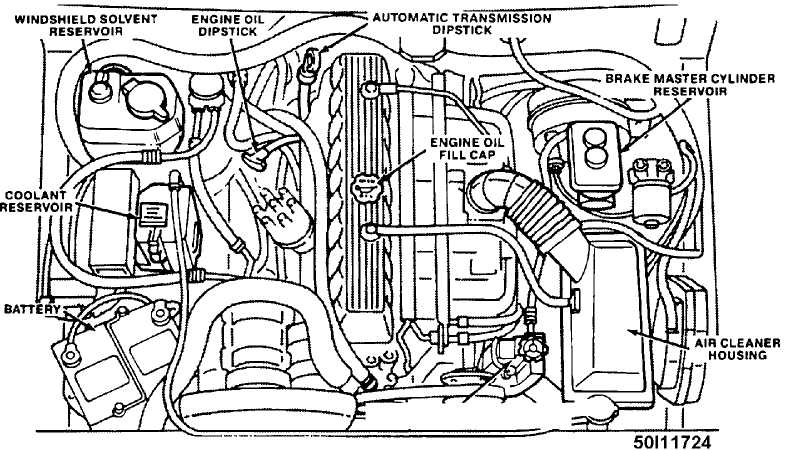
POWER STEERING RESERVOIR/"^ ą× DIPSTICK
Fig. 1: Service Point Locations (Typical) Courtesy of Chrysler Corp.
ADDTIONAL SERVICE INFORMATION
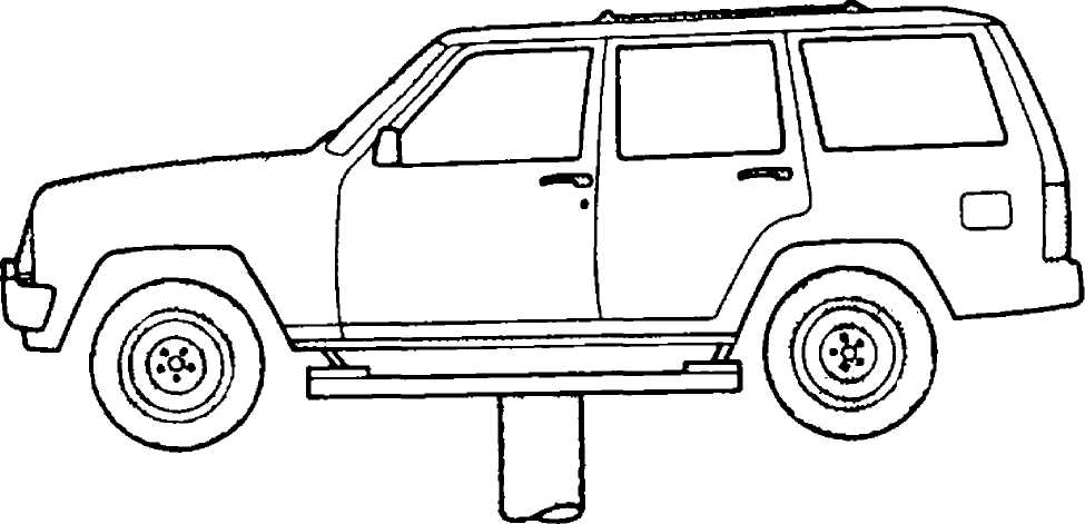
50111732
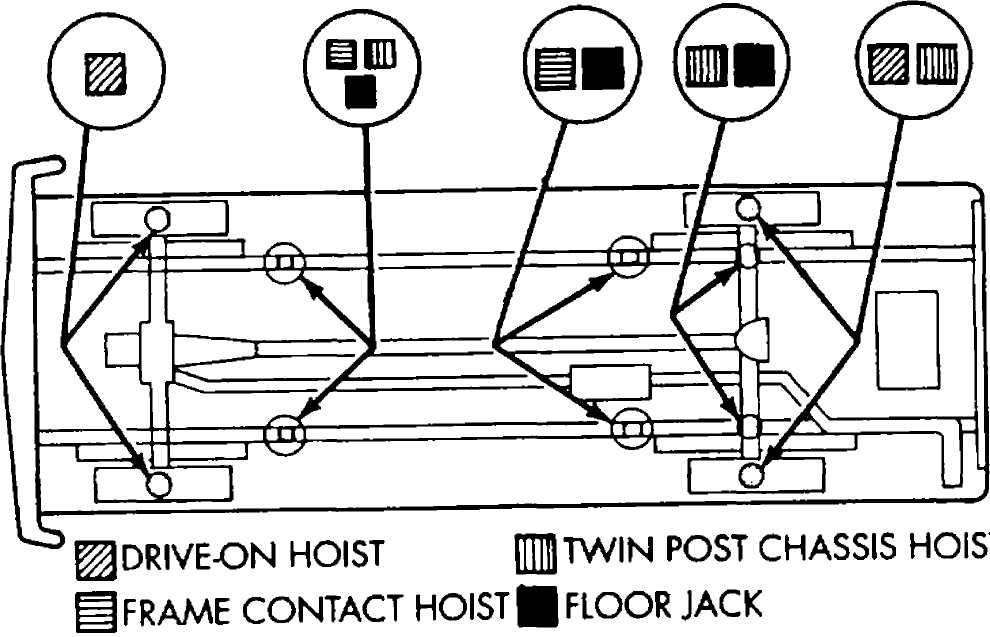
Fig. 2: Hoist Lift Point Locations Courtesy of Chrysler Corp.
NOTE: For more information regarding jacking and hoisting refer to the JACKING & HOISTING article in the
WHEEL ALIGNMENT section.
50F11721
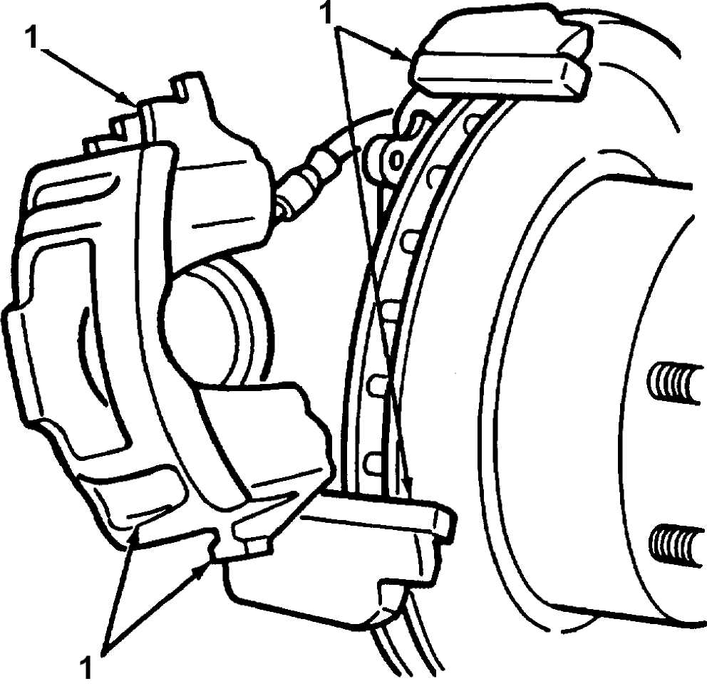
1. LUBRICATION POINTS
Fig. 3: Brake Caliper Lubrication Points Courtesy of Chrysler Corp.
NOTE: For more information regarding brake maintenance refer to the BRAKE SYSTEM article in the BRAKES section.
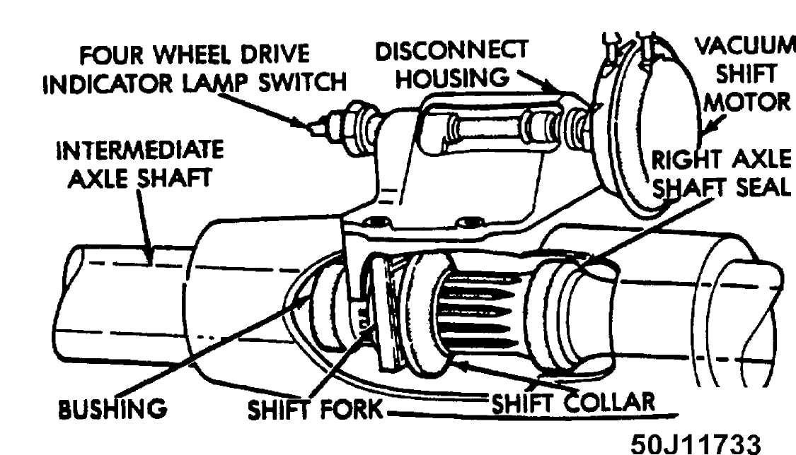
Fig. 4: Front Disconnect Housing Lubrication Point Courtesy of Chrysler Corp.
IDENTIFICATION LABEL LOCATIONS
VEHICLE, LABELS AMD PLATES
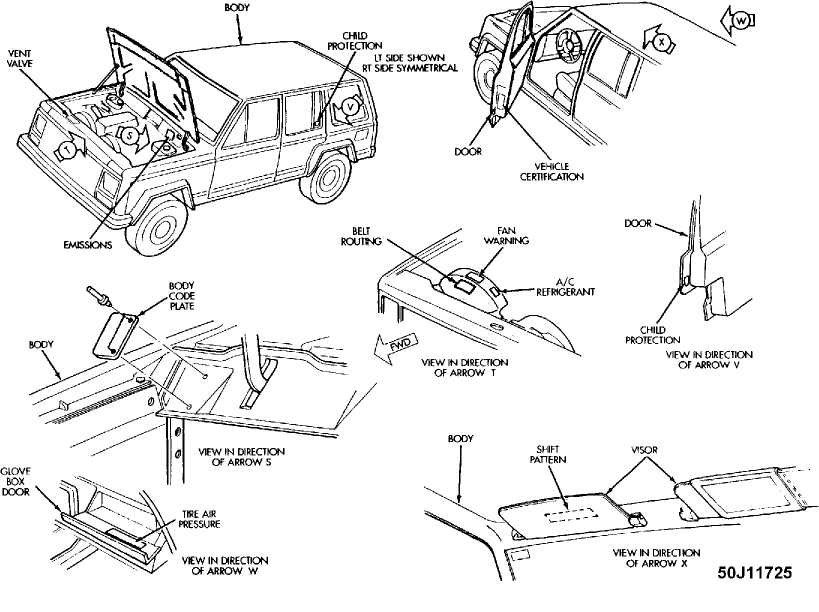
Fig. 5: Identification Label Locations Courtesy of Chrysler Corp.
LUBRICATION SPECIFICATIONS
LUBRICATION SPECIFICATIONS TABLE
Application
Specification
Automatic Transmission
30RH (3-Speed) (1) Mopar 7176 ATF PLUS
AW4 (4-Speed) Dexron-III/Mercon ATF
Brake Master Cylinder DOT 3 (SAE J-1703F) Brake Fluid
Coolant 50/50 Ethylene-Glycol & Water Mix
Engine Oil (2)
Temperature Range
Above 0 F (-18C) SAE 10W-30 API SH/CD ECII
Less Than 60 F (16C) SAE 5W-30 API SH/CD ECII
Front Axle (3) SAE 80W-90 API GL-5 (MIL-L-2105C)
Rear Axle SAE 80W-90 API GL-5 (MIL-L-2105C)
Rear Axle (Trac-Lok) (4) SAE 80W-140 API GL-5
Rear Axle (Trailer Towing) (5) SAE 75W-140 Synthetic
Hydraulic Clutch DOT 3 (SAE J-1703F) Brake Fluid
Manual Transmission SAE 75W-90 API GL-5
Manual Steering Box Multi-Purpose NLGI Grade 2EP
Power Steering Pump Power Steering Fluid
Transfer Case Dexron-IIE ATF
Brake Caliper Bushings GE 661 or DOW 111 Silicone Grease
Caliper Slide Pins GE 661 or DOW 111 Silicone Grease
Wheel Bearings Multi-Purpose NLGI Grade 2EP, GC-LB
Drive Shaft U-Joints Multi-Purpose NLGI Grade 2EP, GC-LB
Steering Linkage (6)(7) ... Multi-Purpose NLGI Grade 2EP, GC-LB
Ball Joints (6)(8) Multi-Purpose NLGI Grade 2EP, GC-LB
Weatherstrip Silicone Spray Lubricant
- DO NOT use Dexron-III ATF, Clutch chatter can result.
- SAE 10W-30 SH/CD ECII is preferred.
- DO NOT use heavier weight lubricant, as it will cause axle
engagement difficulties, use only SAE 80W-90 lube.
(4) - Add 4 ozs. (118 ml) of Limited-Slip differential lubricant
additive when changing fluid.
(5) - For vehicles operating under heavy-duty towing conditions,
use SAE 75W-140 Synthetic lube.
NOTE: Before using SAE 75W-140 Synthetic the old fluid must be DRAINED and FLUSHED with clean mineral based (non-synthetic) axle lubricant. Then refill with new synthetic lube.
- Use low pressure grease gun to prevent seal damage.
- Fill until lubricant squeezes out from the base of seals.
- Fill ball joint until seal starts to swell.
FLUID CAPACITIES
FLUID CAPACITIES TABLE
Application Quantity (1)
A/C System R-12 Refrigerant Capacity
1989-90 36-40 Ozs.
1991-93
Cherokee 2-Door 32 Ozs.
Cherokee 4-Door 38 Ozs.
1994 (up to 12/93)
Cherokee 2-Door 32 Ozs.
Cherokee 4-Door 38 Ozs.
A/C System R-134a Refrigerant Capacity (2)
1994-96 (from 1/94) 32 Ozs.
Automatic Transmission (3) 30RH (3-Speed)
Fluid Change 4.0 Qts . (3 . 8L)
Overhaul (Dry Fill) 8.75 Qts. (8.2L)
AW4 (4-Speed)
Fluid Change 2.0 Qts. (1.7L)
Overhaul (Dry Fill) 8.5 Qts. (8.0L)
Cooling System
2.5L (4) 10.0 Qts. (9.5L)
4.0L (5) 12.0 Qts. (11.4L)
Engine Oil (6)
2.5L 4.0 Qts. (3.8L)
4.0L 6.0 Qts. (5.7L)
Fuel Tank 20.2 Gals. (76.4L)
Manual Transmission (7)
AX4 (4-Speed AISIN) 7.4 Pts. (3.5L)
T4 (4-Speed Borg-Warner) 3.9 Pts. (1.8L)
AX5 (5-Speed AISIN)
2.5L (2WD) 7.0 Pts. (3.5L)
2.5L (4X4) 6.6 Pts. (3.2L)
T5 (5-Speed Borg-Warner) 4.5 Pts. (2.1L)
AX15 (5-Speed AISIN)
4.0L (2WD) 6.4 Pts. (3.1L)
4.0L (4X4) 6.5 Pts. (3.15L)
Transfer Case
Command-Trac (NV 231) 2.2 Pts. (1.0L)
Selec-Trac (NV 242) 3.0 Pts. (1.4L)
Drive Axles (7)
Front Axle (Model 30)
Command-Trac (Disconnect) 3.76 Pts. (1.65L)
(Disconnect Housing) (8) 5.0 Ozs. (0.15L)
Selec-Trac (Non-Disconnect) 3.13 Pts. (1.5L)
Rear Axle
1989-94 (9) 2.5 Pts. (1.2L)
1995-96
Model 35 (9) 3.5 Pts. (1.6L)
8-1/4" (9) 4.4 Pts. (2.1L)
(1) - Capacities are recommended or calculated levels. Always use
dipstick (if available) to measure level.
- Use of R-12 in a R-134a system will result in SEVERE DAMAGE
- Total quantity required will vary, after adding amount shown
check dipstick and fill to proper level.
- Includes 2.3 qts. (2.2L) for coolant recovery bottle.
- Includes 1.0 qt. (0.9L) for coolant recovery bottle.
- Includes Filter.
- Fill to bottom edge of filler plug hole.
- Add 5 ozs. of gear lubricant through indicator switch hole.
- If equipped with TRAC-LOK, add 4 ozs. of Limited-Slip
differential lubricant additive first, then add new fluid.
WHEEL & TIRE SPECIFICATIONS
WHEEL & TIRE SPECIFICATIONS TABLE
Wheel Size Tire Size
Cherokee
15x6 & 15x7 (Aluminum Or Steel) P195/75R15
15x6 & 15x7 (Aluminum Or Steel) P205/75R15
15x6 & 15x7 (Aluminum Or Steel) P215/75R15
15x6 & 15x7 (Aluminum Or Steel) P225/75R15
Wagoneer
15x6 (Aluminum/Steel) P205/75R15
All Models
16-Inch Wheels Compact Spare Tire
TIRE REPLACEMENT
CAUTION: Always ensure all 4 tires on the vehicle are the same size, except when using the temporary spare. The use of mismatched tires may cause unpredictable handling. Replacing original tires with tires of a different size may result in false speedometer and odometer indications.
TIRE INFLATION
The tire specification decal is located in the glove box. WHEEL TIGHTENING
Tighten the lug nuts firmly in a crisscross pattern as shown in Fig. 6. Tighten per following specifications. Always position wheel locking nut opposite valve stem in position indicated. See Fig. 6.
1989-92
Tighten lug nuts in crisscross pattern to 80-110 ft. lbs. (109-150 N.m).
m) .
1993
Tighten lug nuts in crisscross pattern to 95 ft. lbs. (129 N.
1994-96
Tighten lug nuts in crisscross pattern to 85-110 ft. lbs. (115-149 N.m).
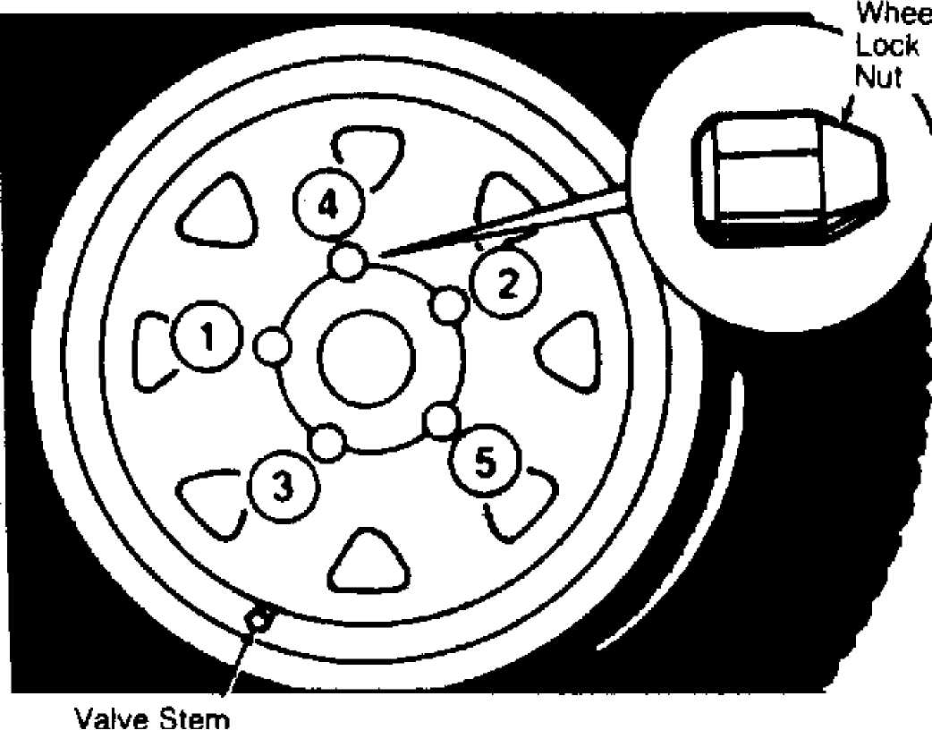
Fig. 6: Wheel Locking Nut Location Courtesy of Chrysler Corp.
BATTERY SPECIFICATIONS
CAUTION: When battery is disconnected, vehicles equipped with computers may lose memory data. When battery power is restored, driveability problems may exist on some vehicles. These vehicles may require a relearn procedure. See the COMPUTER RELEARN PROCEDURES article in the GENERAL INFORMATION section.
All gasoline engine equipped models use BCI group 58 batteries with 390 to 500 Cold Cranking Amp rating.
CAUTIONS & WARNINGS
SUPPLEMENTAL RESTRAINT SYSTEM (SRS) AIR BAG SYSTEM
NOTE: See the AIR BAG RESTRAINT SYSTEM article in the ACCESSORIES/SAFETY EQUIPMENT Section.
The SRS has no user-servicable parts. Always have servicing done by an authorized dealer.
When performing maintenance on air bag equipped vehicles always observe proper safety precautions.
WARNING: To avoid injury from accidental air bag deployment, read and carefully follow all warnings and service precautions. See appropriate AIR BAG RESTRAINT SYSTEM article in the ACCESSORIES/SAFETY EQUIPMENT section.
CAUTION: Disconnect negative battery cable before servicing any air bag system, steering column or passenger side dash component. After any repair, turn ignition key to the ON position from passengerÆs side of vehicle in case of accidental air bag inflation
ANTI-LOCK BRAKE SYSTEM (ABS)
CAUTION: Never mix different diameter tires. On loose or uneven surfaces, the ABS system may require longer stopping distances than conventional brake systems. Exercise caution when removing mud or snow from the wheels so as not to damage the ABS wiring or speed sensors.
BATTERY WARNING
WARNING: When battery is disconnected, vehicles equipped with computers may lose memory data. When battery power is restored, driveability problems may exist on some vehicles. These vehicles may require a relearn procedure. See appropriate COMPUTER RELEARN PROCEDURES article in the GENERAL INFORMATION section below.
REPLACING BLOWN FUSES
Before replacing a blown fuse, remove ignition key, turn off all lights and accessories to avoid damaging the electrical system. Be sure to use fuse with the correct indicated amperage rating. The use of an incorrect amperage rating fuse may result in a dangerous electrical system overload.
BRAKE PAD WEAR INDICATOR
Indicator will cause a squealing or scraping noise, warning that brake pads need replacement.
CATALYTIC CONVERTER
Continued operation of vehicle with a severe malfunction could cause converter to overheat, resulting in possible damage to converter and vehicle.
COOLANT (PROPYLENE-GLYCOL FORMULATIONS)
CAUTION: To avoid possible damage to vehicle use only ethylene-glycol based coolants with a mixture ratio from 44-68% anti-freeze. DO NOT use 100% anti-freeze as it will cause the formation of cooling system deposits. This results in coolant temperatures of over 300 F (149C) which can melt plastics. 100% anti-freeze has a freeze point of only -8┬░ F (-22C).
CAUTION: Propylene-Glycol Mixtures has a smaller temperature range than Ethylene-Glycol. The temperature range (freeze-boil) of a 50/50 Anti-Freeze/Water Mix is as follows:
Propylene-Glycol -26 F (-32C) - 257 F (125C) Ethylene-Glycol -35 F (-37C) - 263 F (128C)
CAUTION: Propylene-Glycol/Ethylene-Glycol Mixtures can cause the destabilization of various corrosion inhibitors. Also Propylene-Glycol/Ethylene-Glycol has a different specific gravity than Ethylene-Glycol coolant, which will result in inaccurate freeze point calculations.
ELECTROSTATIC DISCHARGE SENSITIVE (ESD) PARTS
WARNING: Many solid state electrical components can be damaged by
static electricity (ESD). Some will display a warning label, but many will not. Discharge personal static electricity by touching a metal ground point on the vehicle prior to servicing any ESD sensitive component.
ENGINE OIL
CAUTION: Never use non-detergent or straight mineral oil. FUEL SYSTEM SERVICE
WARNING: Relieve fuel system pressure prior to servicing any fuel system component (fuel injection models).
HALOGEN BULBS
WARNING: Halogen bulbs contain pressurized gas which may explode if overheated. DO NOT touch glass portion of bulb with bare hands. Eye protection should be worn when handling or working around halogen bulbs.
RADIATOR CAP
CAUTION: Always disconnect the fan motor when working near the
radiator fan. The fan is temperature controlled and could start at any time even when the ignition key is in the OFF position. DO NOT loosen or remove radiator cap when cooling system is hot.
RADIATOR FAN
WARNING: Keep hands away from radiator fan. Fan is controlled by a thermostatic switch which may come on or run for up to 15 minutes even after engine is turned off.
AXLE FLUID
CAUTION: Axle lubricant should be changed whenever the axle has
been submerged in water. Water can enter through the axle vent hole and contaminate the lubricant.
COMMAND-TRAC (4WD)
CAUTION: NEVER operate a Command-Trac vehicle in 4WD on dry,
hard-surfaced roads for a sustained period. Use 4L only when needed for added pulling power. Operating vehicle in 4WD mode on such roads will cause stress and possible damage to components, as well as make shifting difficult. To reduce shifting effort, drive vehicle in Reverse for a few feet, or drive off hard-surfaced road momentarily to allow tire slippage.
FRONT AND REAR DIFFERENTIALS (4WD)
CAUTION: DO NOT use water, steam, kerosene or gasoline for flushing a differential. ONLY use a flushing oil.
TRAC-LOK DIFFERENTIALS (4WD)
CAUTION: DO NOT flush a rear axle Trac-Lok differential. Trac-Lok differentials may be cleaned only by disassembling the unit and wiping the components with clean, lint-free cloth.
CAUTION: NEVER attempt to engage Low range when vehicle is moving faster than 2-3 MPH, as transfer case damage may result.
OIL FILTER
CAUTION: Verify that proper Oil Filter is being used. Filters with metric threads (M20 x 1.5) must be used with some engines. Other engines use SAE type (3/4" x 16) threads, and must use an oil filter with these threads. Possible engine damage can occur with improper oil filter.
WHEEL & TIRE WARNINGS
CAUTION: Replacing original tires with different size tires may
result in false speedometer and odometer indications. Check with dealer before using different size tires on vehicle.
CAUTION: Ensure all 4 wheels on vehicle have same tire size, type and circumference in order to provide proper vehicle handling. DO NOT mix radial-ply with bias-ply or bias-belted tires. On 4WD vehicles, if tire size, type and circumference on all 4 wheels are not the same, gear shifting will be adversely affected and can damage transfer case.
CAUTION: Temporary-use spare tires are for emergency use only. DO
NOT drive vehicle faster than 50 MPH or more than 100 miles when using spare tire. DO NOT operate vehicle in 4WD mode when using spare tire, as damage to transfer case can result. Temporary-use spare tires have a total tread life of 3,000 miles.
WARRANTY INFORMATION
CAUTION: Due to the different warranties offered in various regions and the variety of after-market extended warranties
available, please refer to the warranty package that came with the vehicle to verify all warranty options.
BASIC NEW CAR WARRANTY
Jeep Corporation warrants to the original purchaser that the vehicle is free from defects under normal use and service for 12 months or 12,000 miles, whichever comes first.
3/36 OR 7/70 CHOICE
From 1992-94, Jeep owners may choose either 3-year/36,000 mile basic warranty coverage, or 12-month/12,000 mile basic warranty with 7-year/70,000 mile powertrain protection.
POWERTRAIN PROTECTION LIMITED WARRANTY
Begins at 12 months or 12,000 miles and lasts for 7 years or 70,000 miles, whichever comes first. Warranty covers Engine, Transmission, Transfer Case, and Drive Shaft/Drive Axle(s) for RWD & 4WD.
Items not covered include, normal scheduled maintenance, tune-ups, clutch adjustments, lack of proper maintenance, and vehicles on which the mileage cannot readily be determined. A $100.00 deductible on 2WD models and a $150.00 deductible on 4WD models applies to each repair visit.
Powertrain Warranty also covers cost of towing to nearest Jeep Dealer if vehicle cannot be driven due to failure of a covered powertrain part.
ANTI-CORROSION PERFORATION WARRANTY
Warrants the sheet metal parts of the vehicle against
perforation (rust-through) due to corrosion. It covers any body sheet metal panel for unlimited mileage during the first 36 months. Outer-body sheet metal panels are covered for 7 years or 100,000 miles, whichever occurs first.
CUSTOMER ONE CARE WARRANTY (1995-96)
All 1995-96 Chrysler Corporation vehicles are covered by the Customer One Care Warranty, which provides 3 year/36,000 mile coverage.
Warranty coverage can be transferred to at no cost to second owner and begins on the earlier of two start dates:
Date original customer took delivery.
Date vehicle was put into service (Demo).
Warranty does not cover any repair due to poor or improper maintenance. Warranty does not cover costs of damage due to use of contaminated fluids and/or the use of fluids not recommnded in the vehicles owners manual.
Warranty does not cover any costs of scheduled maintenance, or the cost of worn wiper blades, worn brake pads/linings or worn clutch linings. These are normal maintenance parts that all vehicles require.
BASIC NEW CAR LIMITED WARRANTY (1995-96)
Warranty covers any repairs to vehicle components (tires
excluded) which have proven defective in material and workmanship during normal use. Warranty repairs (parts and labor) will be made by the dealer at no charge. Beginning at warranty start date, warranty lasts for 36 months or 36,000 miles, whichever occurs first.
Warranty covers every Chrysler supplied part of vehicle EXCEPT its tires and OKI cellular telephone (Tires and Telephone are covered by seperate warranties offered by their manufacturers).
Under the 36-month/36,000-mile warranty, the following items are only warranted for the first 12 months or 12,000 miles, whichever occurs first:
Brakes (Rotors, Pads, Linings & Drums)
Wiper Blades
Clutch Discs
EMISSION DEFECT WARRANTY (EXCEPT CALIFORNIA)
It warrants that vehicle meets Federal emissions standards in force at time of vehicleÆs manufacture. Warranty covers the cost of repair or adjustment of any parts of vehicleÆs emission control systems that are defective in material, workmanship or factory preparation, but ONLY IF the defect causes the vehicle to fail to meet Federal standards. Begins at warranty start date and lasts for 5 years or 50,000 miles, whichever occurs first.
EMISSION PERFORMANCE WARRANTY (EXCEPT CALIFORNIA)
It begins at warranty start date and lasts for 5 years or 50, 000 miles, whichever comes first. This warranty applies only under the following conditions:
Vehicle failed a Federally-approved state or local emissions
test.
Vehicle has been maintained and operated properly up until
the time of testing.
Owner faces a penalty or other sanctions because of the
vehicleÆs failure to pass the local emissions test.
The following components and systems are covered: Carburetor Feedback Control System, Electronic Fuel Injection System, Air Cleaner Vapor Containment Door System, Electronic Spark Control, Electronic Control Module, Vapor Storage Canister and Controls, Deceleration Throttle Control, EGR Valve & Control System, Air Pump, Belt & Pulley, Air Injection Controls, PCV Valve, Catalytic Converter, Vacuum Hoses, Clamps, Fittings & Tubing used in these components and systems, Vacuum, Temperature, Altitude, Speed and Time-Sensitive Valves and Switches used in these components and systems.
EMISSION PERFORMANCE WARRANTY (CALIFORNIA)
If vehicle fails a Smog Check inspection, all necessary repairs and adjustments will be made by manufacturer to ensure that your vehicle passes the inspection. Warranty begins at warranty start date and lasts for a period of 3 years or 50,000 miles, whichever occurs first.
EMISSION DEFECTS WARRANTY (CALIFORNIA)
If any emission-related part on your vehicle is defective, the part will be repaired or replaced by manufacturer for a period of
3 years or 50,000 miles, whichever occurs first. Warranty begins at warranty start date and lasts for a period of 3 years or 50,000 miles, whichever occurs first.
The following emission-related parts are warranted for 7 years or 70,000 miles, whichever occurs first, and will be repaired or replaced by manufacturer if found to be defective in material or workmanship: Catalytic Converter, Intake Manifold, Carburetor, Throttle Body, Injectors, Fuel Tank, Exhaust Manifolds (4.0L).
ROADSIDE ASSISTANCE (1995-96)
Included in the Customer One Care Warranty is 24 Hour Roadside Assistance coverage, which provides the following services:
Flat Tire Service
Out of Gas
Battery Jump Assistance
Lockout Service
Towing Service
NOTE:
24 Hour Roadside Assistance phone number is 800-521-2779
FUSES & CIRCUIT BREAKERS
Fuse panel is located at the lower left side of dash on most
models.
17
11
93C44570
Fig. 7: Fuse Panel Identification (1989-90 Models) Courtesy of Chrysler Corp.
Fuse & Circuit Breaker Identification
1-25 Amp (Natural)
Rear Washer/Wiper 2-15 Amp (Blue)
Radio, Cigarette Lighter 3-25 Amp (Natural)
Blower Motor 4-20 Amp (Yellow)
Turn Signal, Back-Up Lights, Rear Window Defogger Relay 5-10 Amp (Red)
Dome Light, Courtesy Lights, Glove Box Light, Cargo Light,
Radio & Clock Memories, Power Mirrors, Teltak Connector
Headlight Delay, Chime Module, Overhead Console 6-15 Amp (Blue)
Hazard Warning System, Stoplights 7-10 Amp (Red)
Parking Lights, Headlamps On Warning Chime/Buzzer,
Instrument Panel Light Dimmer 8-7.5 Amp (Violet)
Gauges, Instrument Cluster, Seat Belt Warning 9-5 Amp (Tan)
Instrument Panel Illumination
10 - 25 Amp (Natural)
Rear Window Defogger
11 - 30 Amp (Circuit Breaker)
Power Door Locks, Power Seats, Trailer Towing Wiring Harness
12 - 10 Amp (Red)
ETR Radio, Power Antenna
13 - 7.5 Amp (Violet)
Transmission Control Unit
14 - 25 Amp (Natural)
Headlight Delay
15 - 4.8 Amp (Circuit Breaker)
Front Wiper
16 - 30 Amp (Circuit Breaker)
Power Windows
17 - 10 Amp (Red)
Clock 18-2 Amp (Gray)
Anti-Lock Brake System 19 - 15 Amp (Blue)
Flash-to-Pass
10
91C44570
Fig. 8: Fuse Panel Identification (1991 Models) Courtesy of Chrysler Corp.
Fuse & Circuit Breaker Identification
1-25 Amp (Natural)
Rear Washer/Wiper 2-15 Amp (Blue)
Radio, Cigarette Lighter, Illumination Relay (Clock) 3-25 Amp (Natural)
Blower Motor 4-20 Amp (Yellow)
Turn Signal, Back-Up Lights, Rear Window Defogger Relay 5-10 Amp (Red)
Dome Light, Courtesy Lights, Glove Box Light, Cargo Light,
Radio Memory, Power Mirrors, Teltak Connector 6-15 Amp (Blue)
Hazard Warning System, Stoplights 7-10 Amp (Red)
Parking Lights, Headlight Warning Chime/Buzzer, Instrument
Panel Light Dimmer 8-7.5 Amp (Violet)
Gauges, Instrument Cluster, Seat Belt Warning, 9-5 Amp (Tan)
Instrument Panel Illumination
10 - 25 Amp (Natural)
Rear Window Defogger
11 - 30 Amp (Circuit Breaker)
Power Door Locks, Power Seats, Trailer Towing Wiring Harness
12 - 10 Amp (Red)
ETR Radio, Power Antenna 13-2 Amp (Gray)
Anti-Lock Brake System
14 - 25 Amp (Natural)
Headlight Delay, Horns, Security Alarm
15 - 4.8 Amp (Circuit Breaker)
Front Wiper
16 - 30 Amp (Circuit Breaker)
Power Windows
17 - 10 Amp (Red)
Clock, Security Alarm (Ign) 18-2 Amp (Gray)
Anti-Lock Brake System 19 - 15 Amp (Blue)
Flash-to-Pass, Security Alarm
UNDERHOOD POWER DISTRIBUTION CENTER IDENTIFICATION (1991)
Fig. 9: Power Distribution Center Identification (1991) Courtesy of Chrysler Corp.
WARNING: Always disconnect battery ground cable before servicing
"high-current fuses. It is recommended that "high-current" fuses be replaced by a qualified technician.
50A11650
Fuse & Circuit Breaker Identification
1-60 Amp (Blue)
Alternator Output 2-30 Amp (Green)
Engine Control (ECU) - Fuel Pump, Injectors, Ignition Coil,
Oxygen Sensors, Alternator Field, Engine Controller
Automatic Transmission Controller (ATCU) 3-50 Amp (Red)
Fuse Block 4 - Not Used 5-40 Amp (Orange)
Headlamp Switch 6-60 Amp (Blue)
Ignition Switch - Engine Controller, Fuel Pump Relay,
Automatic Shutdown Relay Coil 7-40 Amp (Orange)
Heated Rear Window, Starter Solenoid 8-30 Amp (Green)
ABS Pump Motor 9-30 Amp (Green)
ABS System
10 - 60 Amp (Blue)
Alternator Output
11 - 15 Amp (Blue)
Ignition Switch - Back-up Lamps, A/C Relay Coil,
Shift Selector, Speed Control, Aux. Cooling Fan Relay Coil
12 - 15 Amp (Blue)
Auxilliary Lamps - Fog Lamps, Underhood Lamps
13 - 20 Amp (Yellow)
Auxilliary Fan
14 - 10 Amp (Red)
Automatic Transmission
15 - 15 Amp (Blue)
Hazard Lamps - Hazard Flasher, Brake Switch 16-2 Amp (Gray)
ABS Battery
Relay Identification
A - Radiator Fan Relay
ąÆ - Fuel Pump Relay
ąĪ - A/C Clutch Relay
D - Auto Shutdown Relay
E - Starter Relay
F - ABS Yellow Indicator Relay
G - ABS Modulator Relay
FUSE PANEL IDENTIFICATION (1992 Models)
The fuse block is to the left of the steering column, under the instrument panel.
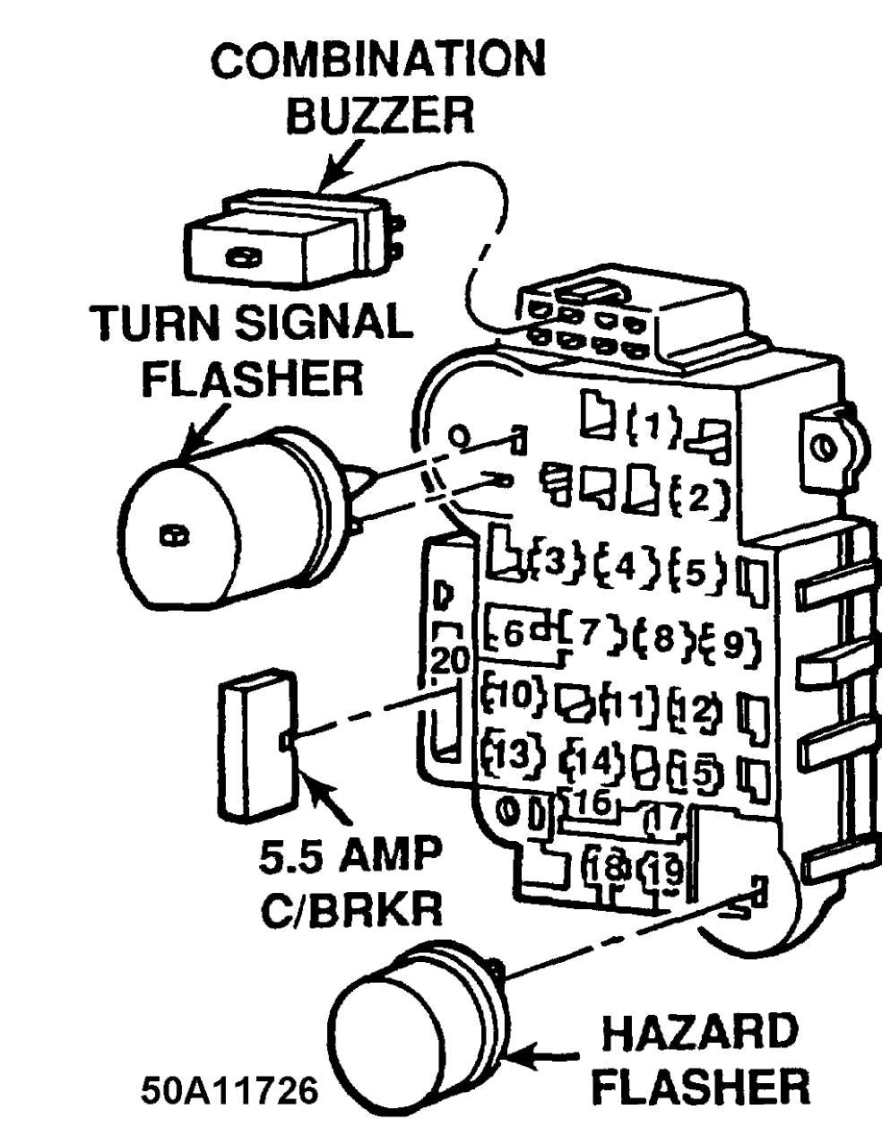
Fig. 10: Fuse Panel Identification (1992 Models) Courtesy of Chrysler Corp.
Fuse & Circuit Breaker Identification
1-25 Amp (Natural)
Rear Window Wiper, Washer 2-15 Amp (Lt. Blue)
Radio, Cigar Lighter, Dome Lamp 3-10 Amp (Red)
Security Alarm Module 4-15 Amp (Lt. Blue)
Headlamp Dimmer Switch, Security Alarm Module,
Security Alarm Relay 5-25 Amp (Natural)
Blower Motor 6-30 Amp (Circuit Breaker)
Power Door Locks, Power Seats, Trailer Towing Wiring Harness
Keyless Entry 7-2 Amp (Pink)
Antilock Brakes (ABS) 8-20 Amp (Yellow)
Turn Signal Flasher 9-10 Amp (Red)
Radio/Clock & Memory, Courtesy Lights, Glove Box, Cargo,
Dome Lamps, Teltak Connector, Illuminated Entry
- Not Used
- 25 Amp (Natural)
Headlamp Delay Module, Horns, Security Alarm Module
- Not Used
- Not Used
- 10 Amp (Red)
Power Antenna
15 - 15 Amp (Lt. Blue)
Instrument Panel Lamps, Clock, Radio/Clock & Memory, Headlamp Switch, Parking Lamps
16 - 30 Amp (Circuit Breaker)
Power Windows
17 - 7.5 Amp (Violet)
18 19
20
Instrument Cluster Guages, Headlamp Delay Module, Chime Module, Overhead Console
- 25 Amp (Natural)
Heated Rear Window
- 5 Amp (Tan)
Instrument Panel Lamps, Radio Illumination
- 5.5 Amp (Circuit Breaker)
Windshield Wiper/Windshield Washer
POWER DISTRIBUTION CENTER IDENTIFICATION (1992 Models)
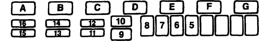
4 3 2 1
50C11652
Fig. 11: Power Distribution Center Identification (1992 Models) Courtesy of Chrysler Corp.
WARNING: Always disconnect battery ground cable before servicing
"high-current fuses. It is recommended that "high-current" fuses be replaced by a qualified technician.
Fuse & Circuit Breaker Identification
1-60 Amp (Blue)
Alternator Output 2-30 Amp (Green)
Engine Control (ECU) - Fuel Pump, Injectors, Ignition Coil,
Oxygen Sensors, Alternator Field, Engine Controller
Automatic Transmission Controller (ATCU) 3-40 Amp (Orange)
Fuse Block 4-20 Amp (Yellow)
Hazard Lamps 5-40 Amp (Orange)
Headlamp Switch 6-60 Amp (Blue)
Ignition Switch - Engine Controller, Fuel Pump Relay,
Automatic Shutdown Relay Coil 7-40 Amp (Orange)
Heated Rear Window, Starter Solenoid 8-40 Amp (Orange)
ABS Pump Motor 9-60 Amp (Blue)
Alternator Output
10 - 30 Amp (Green)
ABS System
11 - 15 Amp (Blue)
Ignition Switch - Back-up Lamps, A/C Relay Coil,
Shift Selector, Speed Control, Aux. Cooling Fan Relay Coil
12 - 10 Amp (Red)
Automatic Transmission
13 - 15 Amp (Blue)
Auxilliary Lamps - Fog Lamps, Underhood Lamps
14 - 20 Amp (Yellow)
Engine Controller
15 - 20 Amp (Yellow)
Aux. Cooling Fan
16 - 10 Amp (Red)
Radio Memory, Clock Memory, Ignition Off Draw
Relay Identification
A - Aux. Cooling Fan Relay
ąÆ - Fuel Pump Relay
ąĪ - ABS Pump Relay
D - Air Conditioning Relay
E - Auto Shutdown Relay
F - Starter Relay
G - ABS System Relay
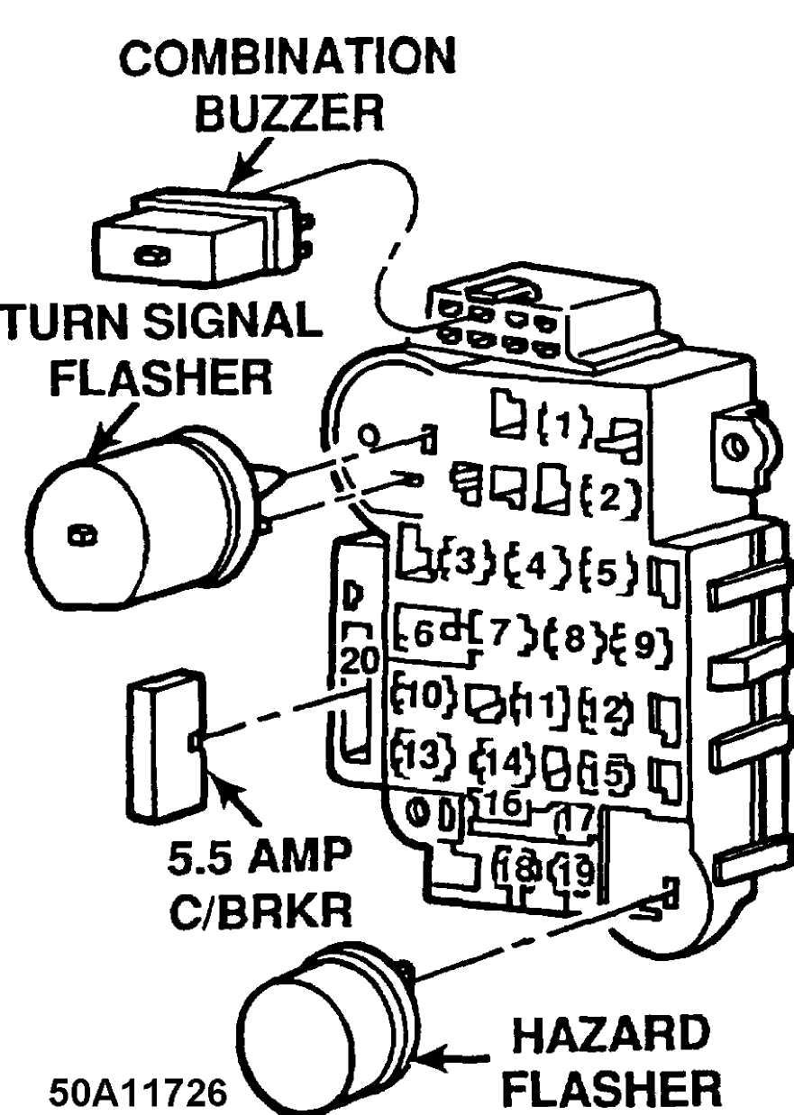
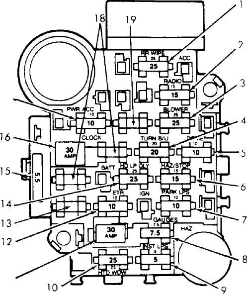
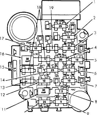
Fig. 12: Fuse Panel Identification (1993-96) Courtesy of Chrysler Corp.
Fuse & Circuit Breaker Identification
1-25 Amp (Natural)
Rear Window Wiper, Washer 2-15 Amp (Lt. Blue)
Radio, Cigar Lighter, Dome Lamp (1993) 3 - Not Used 4-15 Amp (Lt. Blue)
Flash to Pass 5-25 Amp (Natural)
Blower Motor 6-30 Amp (Circuit Breaker)
Power Windows 7-2 Amp (Pink)
Antilock Brakes (ABS) 8-20 Amp (Yellow)
Turn Signal Flasher 9-10 Amp (Red)
Radio/Clock & Memory, Courtesy Lights, Glove Box, Cargo,
Dome Lamps, Telltales
- Not Used
- 25 Amp (Natural)
Headlamp Delay Module, Horns
- Not Used
- 20 Amp (Yellow)
Power Door Locks
- Not Used
- 15 Amp (Lt. Blue)
Instrument Panel Lamps, Clock, Radio/Clock & Memory, Headlamp Switch, Parking Lamps
16 - 30 Amp (Circuit Breaker)
Power Seats, Trailer Tow
17 - 7.5 Amp (Violet)
Instrument Cluster Guages, Headlamp Delay Module, Chime Module, Overhead Console
18 - 25 Amp (Natural)
Heated Rear Window 19-5 Amp (Tan)
Instrument Panel Lamps, Radio Illumination 20 - 5.5 Amp (Circuit Breaker)
Windshield Wiper/Windshield Washer
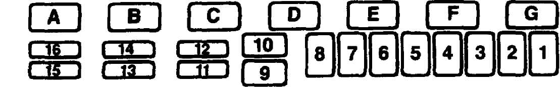
RELAY PANEL IDENTIFICATION (1993-96 MODELS)
The relay panel is to the right of the steering column, under the instrument panel.
50B11727
 Fig. 13: Relay Block Identification (1993-96 Models) Courtesy of Chrysler Corp.
Relay Identification
1 - Illuminated Entry Relay (1993-94)
Not Used (1995-96)
2 - Horn Relay (1993-94)
Dual Flasher Relay (1995-96)
3 4 5
6 7 8 9 10
Rear Window Defogger Relay
Not Used
Not Used (1993-94)
Horn Relay (1995-96)
Not Used
Not Used
Radio Illumination Relay
Power Door Lock (Unlock) Relay
Power Door Lock (Lock) Relay
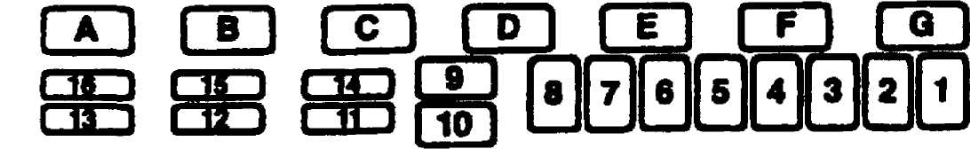
POWER DISTRIBUTION CENTER IDENTIFICATION (1993-96)
50C11652
Fig. 14: Power Distribution Center Identification (1993-96) Courtesy of Chrysler Corp.
WARNING: Always disconnect battery ground cable before servicing
"high-current fuses. It is recommended that "high-current" fuses be replaced by a qualified technician.
Fuse & Circuit Breaker Identification
1-60 Amp (Blue)
Generator Output 2-30 Amp (Green)
Engine Control (ECU) - Fuel Pump, Injectors, Ignition Coil,
Oxygen Sensors, Generator Field, Engine Controller
Automatic Transmission Controller (ATCU) 3-40 Amp (Orange)
Fuse Block 4-20 Amp (Yellow)
Hazard Lamps 5-40 Amp (Orange)
Headlamp Switch 6-50 Amp (Red)
Ignition Switch - Engine Controller, Fuel Pump Relay,
Automatic Shutdown Relay Coil 7-40 Amp (Orange)
Heated Rear Window, Starter Solenoid 8-40 Amp (Orange)
ABS Pump Motor 9-60 Amp (Blue)
Generator Output
10 - 30 Amp (Green)
ABS System
11 - 15 Amp (Blue)
Ignition Switch - Back-up Lamps, A/C Relay Coil,
Shift Selector, Speed Control, Aux. Cooling Fan Relay Coil
12 - 10 Amp (Red)
Automatic Transmission
13 - 15 Amp (Blue)
Auxilliary Lamps - Fog Lamps, Underhood Lamps
14 - 20 Amp (Yellow)
Engine Controller
15 - 20 Amp (Yellow)
Aux. Cooling Fan
16 - 10 Amp (Red)
Ignition Off Draw (1993)
Radio/Clock Memory, Ignition Off Draw, Dome Courtesy(1994-96)
Relay Identification
A - Aux. Cooling Fan Relay
ąÆ - Fuel Pump Relay
ąĪ - ABS Pump Relay
D - Air Conditioning Relay
E - Auto Shutdown Relay
F - Starter Relay
G - ABS System Relay