Ā
1993 Jeep Cherokee
1993 STEERING
Chrysler Corp. Steering Columns
Jeep; Cherokee, Grand Cherokee, Grand Wagoneer, Wrangler
DESCRIPTION & OPERATION
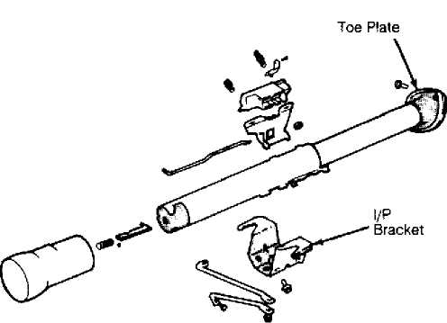
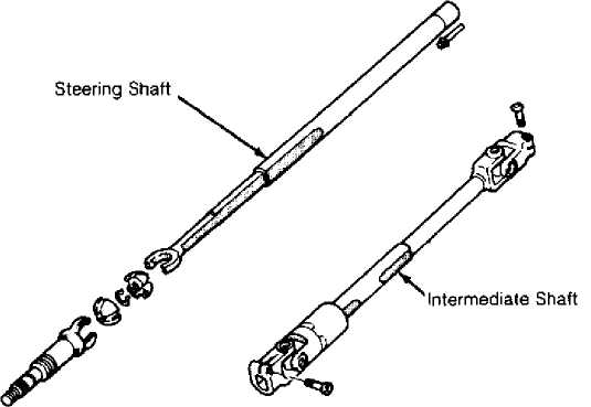
All models use collapsible steering columns. All columns have integral ignition switch and locking device. Optional tilt wheel is available with both A/T and M/T models. Transmission shift linkage is integral on all models except those with floor shift. See Figs. 1 and 2.
Grand Cherokee and Grand Wagoneer models are equipped with driver-side air bag. Steering column on these models is serviced only as an assembly, except for steering wheel, switches and wiring.
WARNING: On models with Supplemental Restraint System (SRS), air bag system MUST be disabled before servicing ANY steering column component. Disabling system will prevent accidental air bag deployment, resulting in possible serious injury or property damage.
AIR BAG DISABLING
BEFORE servicing ANY steering column or air bag component, disconnect and shield negative (ground) battery cable. Wait 2 MINUTES to allow air bag system capacitor to deplete its residual charge. Proceed with steering column service.
Fig. 1: Steering Column & Intermediate Shaft Courtesy of Chrysler Corp.
(Cherokee & Wrangler)

smoua
Fig. 2: Exploded View Of Steering Column (All Others) Courtesy of Chrysler Corp.
REMOVAL & INSTALLATION
STEERING WHEEL & HORN PAD R & I
Removal & Installation (Cherokee & Wrangler)
Disconnect negative battery cable. Place wheels in
straight-ahead position. On models with standard steering wheel,
remove horn button retaining screws from rear of steering wheel.
Disconnect wiring from horn button and remove.
On models with sport steering wheel (round horn button),
remove horn button by pulling button upward. If necessary, remove horn
internal components. Place components in order of removal.
Remove steering wheel retaining nut. Reference mark
steering wheel and steering shaft. Using puller, remove steering
wheel. To install, reverse removal procedure. Align marks made during
removal. Tighten steering wheel retaining nut to specification. See
TORQUE SPECIFICATIONS.
Removal & Installation (Grand Cherokee & Grand Wagoneer)
Disable air bag system. See AIR BAG DISABLING. Ensure
steering wheel is in straight-ahead position. Remove nuts mounting air
bag module to steering wheel. Remove screws securing cruise control
switch to steering wheel. Disconnect wiring connectors. Remove air bag
module and cruise control switch assembly.
Pry trim covers from back of steering wheel and remove
horn switch mounting screws. Disconnect horn wires. Remove horn
switch.
Remove steering wheel retaining nut. Reference mark
steering wheel and steering shaft. Using puller, remove steering
wheel. To install, reverse removal procedure. Align marks made during
removal. Tighten steering wheel retaining nut to specification.
COMBINATION SWITCH R & I (GRAND CHEROKEE & GRAND WAGONEER)
Removal & Installation
1) Disable air bag system. See AIR BAG DISABLING. Remove tilt lever (if equipped). Remove upper and lower steering column covers. Remove steering panel trim panel and knee bolster. Remove steering column-to-mounting bracket retaining nuts. Lower steering column. See
Fig. 2.
2) Using Tamper Proof Torx Bit (TTXR20B2), remove combination switch retaining screws. Gently roll combination switch away from column. Unscrew connector retaining screw from combination switch. Screw will remain in connector. Disconnect connector. Remove switch. To install, reverse removal procedure.
PARK-LOCK CABLE R & I
NOTE: Park-Lock (Shifter/Ignition Interlock on Grand Cherokee and Grand Wagoneer) cable mechanism is used on all models equipped with floor shift and AW-4 transmission (except Wrangler). Park-Lock system locks shifter in PARK position when key switch is in LOCK or ACCESSORY position.
Removal & Installation
Disconnect negative battery cable. Remove lower instrument
panel trim. Remove steering column attaching nuts and lower steering
column. Disconnect park-lock cable from steering column and remove
cable from bracket. See Fig. 2.
Remove center console. Remove moldings, panels,
accelerator pedal bracket and carpet screws. Pull carpet back for access to gear selector lever bellcrank, disconnect park-lock cable and remove cable. To install, reverse removal procedure.
COLUMN SHIFT TYPE STEERING COLUMN R & I
NOTE: Steering column removal is NOT needed for lock plate cover, lock plate, steering shaft retaining ring, canceling cam, turn signal switch, upper bearing preload spring, or ignition switch/lock cylinder removal.
Removal
Disconnect negative battery cable. Remove steering wheel
and horn pad. See STEERING WHEEL & HORN PAD R & I. Remove damper
assembly (if equipped). Remove turn signal lever. Disconnect shift
cable grommet by prying it from shift lever.
Paint alignment marks on intermediate shaft and steering
shaft for installation reference. Disconnect steering shaft from
intermediate shaft. If necessary, remove lower part of instrument
panel, disconnect bracket from instrument panel and lower steering
column.
Disconnect ignition switch, dimmer switch, turn signal
switch, windshield wiper switch and cruise control electrical
connectors. Disconnect park-lock cable (if equipped). Disconnect
steering column toe plate from instrument panel, remove steering
column from vehicle.
CAUTION: When removed from vehicle, steering column must be handled very carefully. The plastic fasteners that maintain the rigidity of the energy-absorbing components could be sheared or loosened.
NOTE: On vehicles equipped with cruise control and manual
transmission, take care not to damage clutch pedal cruise control switch.
Installation
Align lower shaft with lower coupling and insert shaft.
Raise column assembly into position onto studs. Loosely install nuts
and washers in break-away capsules. Pull column rearward. Tighten nuts
to specification. See TORQUE SPECIFICATIONS.
Install NEW shift lever grommet using pliers and back-up
washer to snap grommet into place. Use a multipurpose grease to aid installation. Connect gearshift cable rod to shift lever by snapping rod into grommet with pliers.
Adjust linkage. Place steering wheel on shaft with master
splines aligned. Place damper assembly inside steering wheel (if
equipped). Install steering wheel retaining nut. Tighten to
specification.
Install horn pad assembly. Connect electrical connectors
at steering column jacket. Connect negative battery cable. Test
operation of lights and horn.
On models with automatic transmission, install gearshift
indicator pointer. Slowly move gearshift lever from Low to Park
position, pausing briefly at each position. Readjust pointer as
required. Install instrument panel steering column cover.
FLOOR SHIFT TYPE STEERING COLUMN R & I
Removal & Installation
Removal procedure is same as for column shift with following exceptions: in place of rotating shift bowl, a plastic shroud is fixed to lock housing. Shroud covers jacket and lock inhibitor assembly with a tab holding it in place. Replace shroud by removing key/lock housing from jacket.
OVERHAUL
NOTE: Manufacturer does not recommend overhaul of steering column
on Grand Cherokee and Grand Wagoneer. If service is required, replace steering column as an assembly. Steering wheel, switches and wiring can be serviced separately.
NON-TILT WHEEL COLUMN OVERHAUL
NOTE: If repairs are performed while in vehicle, DO NOT allow shaft to slip out of column.
Disassembly
1) If column is removed from vehicle, attach a column
supporting fixture. See Fig. 3. If the column is in the vehicle,
disconnect negative battery cable. Remove the steering wheel. Refer to
STEERING WHEEL & HORN PAD R & I under REMOVAL & INSTALLATION. Remove
lock plate cover.
WARNING: Lock plate is retained by a very strong spring force.
DO NOT attempt to remove steering shaft snap ring without using appropriate lock plate depressor.
2) Depress lock plate, remove snap ring and discard. Remove
lock plate, cancel cam, upper bearing preload spring and washer.
Remove hazard warning switch knob, press knob inward then turn
counterclockwise, remove from column.

Fig. 3: Attaching Steering Column Support Fixture Courtesy of Chrysler Corp.
Remove turn signal/wiper/cruise control stalk by pulling
straight out from column. Disconnect turn signal wiring harness at
lower end of column.
Remove turn signal/dimmer retaining screws and remove
switch. Guide harness and switch up and out of column. Remove all
other wiring harnesses in steering column.
NOTE: Wrap tape around turn signal wire harness to prevent entanglement during removal.
Turn ignition switch to ON position. Remove key warning
buzzer and contacts as a unit with needle nose pliers. Insert a small
screwdriver into right hand slot adjacent to switch attaching screw
boss. Depress spring latch located at bottom of slot and pull cylinder
out of column.
On models equipped with floor shift, proceed to step 10).
On column shift models, remove gear selector lever upper pivot pin, selector lever and upper bearing thrust washer. Remove 4 screws attaching key/lock cylinder housing to steering column, remove key/lock cylinder housing.
7) Remove thrust cap and ignition switch actuating rod and rack. Remove rack preload spring, shaft lock bolt and spring from housing. Remove shift lever detent plate from housing. See Fig. 4.
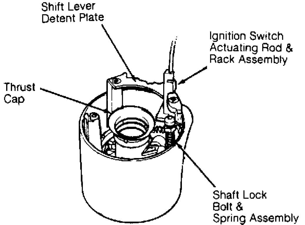
Fig. 4: Identifying Key/Lock Cylinder Housing Courtesy of Chrysler Corp.
8) Use punch to exert force on block tooth to disengage and
remove lock sector. Remove gear selector lever housing and shroud from
steering shaft. Remove gear selector lever spring from housing.
NOTE: Steering column must be removed from vehicle for further disassembly.
9) Remove steering shaft, if not removed earlier. Remove
spring clip from lower bearing retainer, remove retainer, lower
bearing, and adapter. Slide out shift tube.
10) On models equipped with floor shift, remove screws
attaching key/lock cylinder and shroud to column jacket. Remove dimmer switch arm, disengage remote rod from lock rack. Remove key/lock cylinder housing to shroud screws and separate.
11) Remove and separate wave washer from key release lever
pivot. Remove lock rack, lock bolt and preload spring. Use punch to exert force on block tooth to disengage and remove lock sector. Remove gear selector lever housing and shroud from steering shaft.
12) Remove steering shaft, if not removed earlier. Remove spring clip from lower bearing retainer, remove retainer, lower bearing and adapter. Slide out shift tube.
Reassembly
Coat all friction surfaces with grease. Insert key sector
through key/lock cylinder hole. Install lock sector shaft. Ensure
sector turns freely. Install lock rack preload spring. Assemble lock
bolt and rod and install assembly in housing. Mate assembly with lock
sector gear teeth. Install shift lever detent plate on housing. See
Fig. 5.
Install thrust cap and ignition switch actuating rod on
housing. Insert gear selector lever housing lower bearing and align
indentations in shell with projections on housing. Install gear
selector spring in housing.
Install gear selector lever housing and shroud on column.
Rotate housing to ensure that bearing is seated. With gear selector
housing in Park position and lock rack pulled downward, position and
seat key/lock cylinder housing on column. Tighten 4 screws to 40 INCH
lbs. (4.5 N.m).
Insert shift tube in lower end of column and rotate until
shift tube upper key slides into gear selector housing keyway. On
models equipped with floor shift, proceed to step 10). On column shift
models, proceed to next step.
Install key/lock cylinder housing and shroud on steering
column, place key in ignition cylinder and rotate until key is aligned
with keyway in housing. Insert cylinder into housing far enough to
contact switch actuator. Press inward and rotate cylinder. When
aligned, cylinder will move inward and spring-loaded retainer will
snap into place. Cylinder is now locked in column.
Turn key/lock cylinder to ON position and install key/lock
buzzer switch. Move ignition switch to ACC position then back 2 clicks
to OFF position. The remote rod hole in ignition switch should be
centered. Insert remote rod in ignition switch slider hole. Tighten
ignition switch mounting screws to 35 INCH lbs. (4 N.m).
Install lower bearing, adapter, retainer and spring clip
at lower end of column. Install steering shaft into lower end of
column and route through into upper bearing. Position turn signal
switch and wire harness in key/lock housing. Fold wires against
connector and feed down through column. Install wiper wiring harness
and route through column. Align and secure turn signal switch. Tighten
screws to 35 INCH lbs. (4 N.m).
Install dimmer switch actuator arm and tighten screw to 35
INCH lbs. (4 N.m). Route cruise control wiring harness in column (if
equipped). Install turn signal/wiper/dimmer/cruise control switch
stalk on column by pressing straight in. Position thrust washer, upper
bearing preload spring and cancel cam on steering column.
Install hazard warning switch knob. Place lock plate on
shaft, depress lock plate with depressor and install new snap ring.
Install steering wheel. See STEERING WHEEL & HORN PAD R & I. Tighten
steering wheel nut to specification. See TORQUE SPECIFICATIONS.
10) On models equipped with floor shift, install key release
lever return spring over threaded pivot post on housing. Insert key
release finger in lock rack slot and position hole in lever over
threaded pivot post. See Fig. 5. Ensure inner end of spring contacts
release lever.
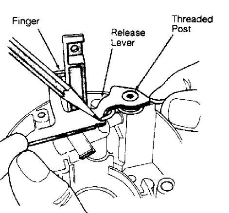
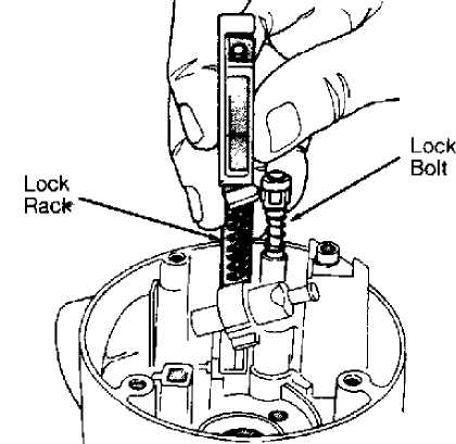
Fig. 5: Removing Lock Rack Courtesy of Chrysler Corp.
& Bolt Release Spring
Raise key release lever slightly. Install lever spring
between lever and boss on housing. Lubricate and place wave washer on
threaded pivot post. Position shroud on key/lock housing. Tighten
screws to 18 INCH lbs. (2 N.m).
Insert short, hooked end of remote rod in lock rack.
Install assembled key/lock housing on steering column and tighten
screws to 60 INCH lbs. (7 N.m). Install key/lock cylinder housing and
shroud on steering column, place key in ignition cylinder and rotate
until key is aligned with keyway in housing.
Insert cylinder into housing far enough to contact switch
actuator. Press inward and rotate cylinder. When parts align, cylinder
will move inward and spring-loaded retainer will snap into place.
Cylinder is now locked in column.
Turn key/lock cylinder to ON position and install
key/lock buzzer switch. Move ignition switch slider to ACC position, then back 2 clicks to OFF position. The remote rod hole in ignition switch should be centered. Insert remote rod in ignition switch slider hole and tighten ignition switch to column screws to 35 INCH lbs. (4 N.m) .
Install lower bearing, adapter, retainer and spring clip
at lower end of column. Install steering shaft into lower end of
column and insert into upper bearing. Position turn signal switch and
wire harness in key/lock housing. Fold wires against connector and
feed down through column jacket. Install wiper wiring harness and
route through column. Align and secure turn signal switch. Tighten
screws to 35 INCH lbs. (4 N.m).
Install dimmer switch actuator arm and tighten screw to
35 INCH lbs. (4 N.m). Route cruise control wiring harness in column
(if equipped). Install turn signal/wiper/dimmer/cruise control switch
stalk on column by pressing straight in. Position thrust washer, upper
bearing preload spring and canceling cam on steering column.
Install hazard warning switch knob. Place lock plate on
shaft, compress plate and install new snap ring. Ensure that new snap
ring is completely seated in groove before removing depressor. Install
steering wheel. Tighten steering wheel nut to specification.
TILT WHEEL COLUMN OVERHAUL
NOTE: Tilt steering can be disassembled in vehicle down to the
column jacket. If further repairs are needed, column must be removed from vehicle.
Disassembly
Remove steering wheel. See STEERING WHEEL & HORN PAD R & I
under REMOVAL & INSTALLATION. Remove column (if required). Attach
column fixture and clamp assembly in vise. See Fig. 3.
Remove tilt release lever. To remove hazard warning knob,
push in knob while unscrewing. Remove ignition key light assembly.
Pull knob off wiper/washer switch assembly. Remove 2 sleeve-to-
wiper/washer switch retaining screws and remove sleeve.
WARNING: Lock plate is retained by a very strong spring force.
DO NOT attempt to remove steering shaft snap ring without using appropriate lock plate depressor.
Rotate wiper switch shaft fully clockwise. Remove shaft by
pulling straight out of wiper/washer switch. Carefully remove plastic
cover from lock plate. Using Lock Plate Depressor (J-23653-A), depress
lock plate. Pry retaining ring from groove, remove and discard ring.
Remove lock plate, canceling cam and upper bearing plate.
Remove switch actuator screw and arm. Remove 3 turn signal switch
attaching screws. Place shift bowl in LOW position. Wrap a piece of
tape around wires to prevent snagging while removing switch and remove
switch.
Turn key/lock cylinder to ON position. Using needle nose
pliers, remove key warning buzzer switch and contacts as one unit.
Remove spring and switch. DO NOT allow spring to fall into steering
column. Insert a small screwdriver into the right-hand slot adjacent
to switch attaching screw boss. Depress spring latch located at bottom
of slot and remove key/lock cylinder.
Remove 3 key/lock cylinder housing cover screws and remove
housing cover. Remove wiper/washer switch. Tilt lever opening shield
and dimmer switch actuator rod may be removed from cap (if necessary).
Remove dimmer switch mounting screws and remove switch. With ignition
switch in ACC position, remove ignition switch mounting screws and
remove switch.
WARNING: Tilt spring guide retainer has strong spring force.
Remove upper bearing race and bearing seat from steering
shaft. Place column in full upward tilt position. Using a large
Phillips head screwdriver, press tilt spring guide inward and turn
counterclockwise until retainer tabs disengage from key/lock housing
lug.
Place column in center most position. Place Pivot Pin
Remover (J-21854-01) over pivot pin. Thread small portion of screw
firmly into pin. Hold screw from turning with one wrench while turning
nut clockwise with a second wrench to withdraw pivot pin from support.
Remove opposite pivot pin in same manner. Use tilt release
lever to disengage lock shoes. Remove bearing housing assembly by
pulling upward to extend rack fully. Move housing assembly to the left
to disengage rack from actuator.
Rotate housing clockwise to free dimmer switch actuator
rod. Remove actuator assembly. Remove lock sector spring retaining
screw and sector spring. Remove lock bolt, lock rack, rack preload
spring and remote rod from key/lock cylinder housing.
Insert a wedge between lock shoes and key/lock cylinder
housing to relieve spring tension tilt release lever pin and lock shoe
pin. Using a punch, remove tilt release lever pin and lock shoe pin.
Remove lock shoes, spring and wedge. Remove upper and lower bearings
and races from key/lock cylinder housing if required.
NOTE: Bearings and races only require removal if damaged. Remove races with hammer and punch and discard. DO NOT reuse components.
12) Remove steering shaft from upper end of steering column. Separate upper and lower steering shaft by folding shaft 90 degrees at flex joint and detaching shaft sections. See Fig. 6. Remove steering column support from column. Remove shift gate from steering support (if required).
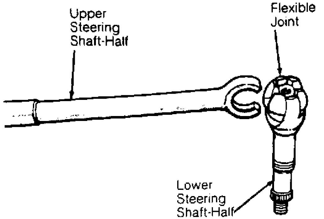
Fig. 6: Identifying Tilt Column Flexible Joint Courtesy of Chrysler Corp.
13) Remove retainer and bearing from lower end of steering column. Remove shift tube retaining ring and thrust washer. Using Puller (J-23072), remove shift tube from bowl. Insert bushing on end of puller in shift tube to force tube from bowl. DO NOT hammer shift tube as plastic joints may shear. See Fig. 7.
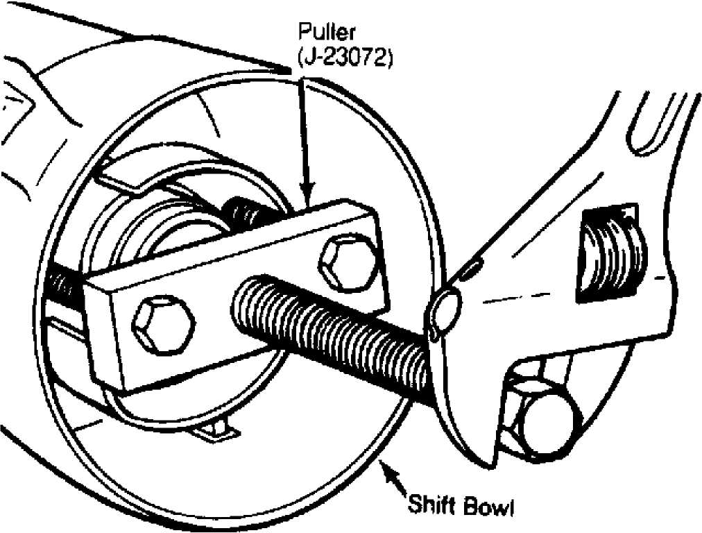
Fig. 7: Removing Shift Tube from Bowl (Tilt Wheel) Courtesy of Chrysler Corp.
14) Tilt upper end of retainer plate toward lower end of column, turn plate counter-clockwise and remove. On column shift models, remove wave washer and shift tube spring. Remove shift bowl from steering column jacket. On floor shift models, remove column shroud from column jacket. Remove key release lever and spring from column shroud.
WARNING: Use only original or exact replacement screws, bolts and nuts to assemble steering column. Use of incorrect hardware could keep column from compressing in a collision. Column-to-instrument panel attaching nuts MUST be tightened to correct torque so that column will break away on impact.
Reassembly
1) During reassembly, coat all friction surfaces with multipurpose grease. If reassembling a floor shift type column, proceed to step 3). To reassemble column shift type column, install shift bowl on steering column jacket. Install shift tube spring, wave washer and retainer plate in shift bowl. Insert shift tube through lower end of column jacket and align tube key spline with shift bowl keyway.
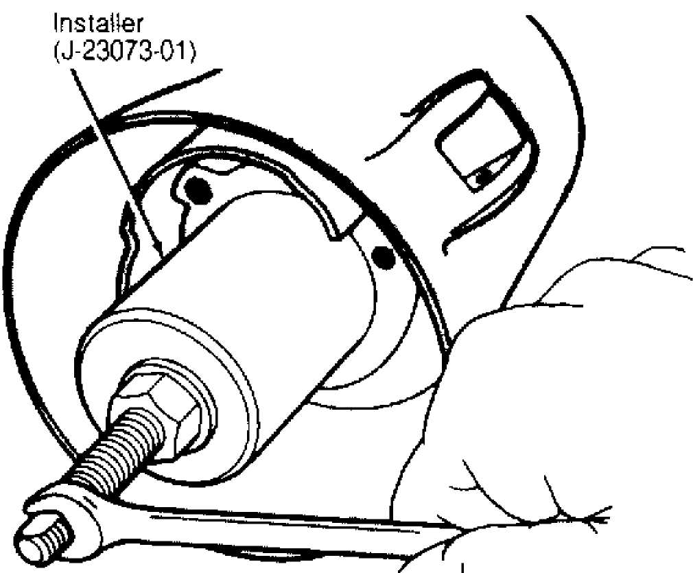
2) Install Installer (J-23073-01) and pull shift tube into bowl. See Fig. 8. Install shift tube thrust washer and retainer plate snap ring. Install column lower bearing. Attach shift gate to steering column support. Install steering column support assembly into column and tighten retaining screws alternately and evenly to 60 INCH lbs. (7 N.m) .
117506
Fig. 8: Installing Shift Tube Courtesy of Chrysler Corp.
(Tilt Wheel)
To reassemble floor shift type column, position key
release lever spring onto lever and install assembly into column
shroud. Install shroud onto steering column jacket. Install retainer
plate into column jacket notches.
Install column support into column jacket by aligning "V"
on support with "V" notch in column jacket. To completely seat
support, press key release lever downward while pressing support into
place. Install steering column support retaining screws and tighten
alternately and evenly to 60 INCH lbs. (7 N.m).
NOTE: Remaining steps apply to either column shift type or floor shift type columns.
5) Install remote rod in column support rod slot. Install
dimmer and ignition switches. Install new races and bearings in
key/lock cylinder housing if old components were removed. Using a .18"
(4.5 mm) diameter rod to aid in alignment, install lock shoes, lock shoe springs and lock shoe pin.
Install tilt release lever, lever spring and lever pin in
key/lock cylinder housing. Insert wedge between housing and lever to
relieve spring tension and ease pin installation.
Install lock bolt in key/lock cylinder housing and engage
it in lock sector cam surface. Install lock rack, rack preload spring
and replacement shim in key/lock cylinder housing. Mate square block
tooth on lock rack to like tooth on lock sector. Tighten screws to 35
INCH lbs. (4 N.m).
Retain lock shoes in disengaged position and install
key/lock housing on column support. Align pivot pin holes in key/lock
cylinder housing with those in column support and install pivot pins.
Seat pins fully using a hammer and punch.
CAUTION: Press housing down firmly while installing pivot pins to avoid damage to holes in column support.
9) Place key/lock cylinder housing in full upward tilt
position. Lubricate tilt spring guide and spring with chassis lube.
Insert tilt spring guide and spring into key/lock cylinder housing.
Using a large Phillips head screwdriver, install spring retainer into
key/lock cylinder housing lugs.
Install key/lock cylinder housing cover and tighten
screws to 60 INCH lbs. (7 N.m). Install gear selector indicator light
assembly (if equipped). Route dimmer switch harness down through
column.
Insert key/lock cylinder into housing far enough to
contact switch actuator. Press inward and rotate cylinder. When
aligned, cylinder will move inward and spring-loaded retainer will
snap into place. Cylinder is now locked in column. Turn key/lock
cylinder to ON position. Install key/lock buzzer switch.
Install turn signal switch, but DO NOT install switch
retaining screws at this time. Install windshield wiper harness and
switch and route harness down through column jacket. Route cruise
control harness (if equipped), down through column jacket.
Install turn signal switch stalk by pushing straight into
column. Install hazard warning knob on hazard warning switch. Install
turn signal retaining screws and tighten to 35 INCH lbs. (4 N.m).
Install upper bearing race in key/lock cylinder housing.
Install cruise control harness (if equipped). Install
upper bearing preload spring, canceling cam and lock plate. Depress
lock plate with depressor and install new snap ring. See Fig. 9.
Install lock plate cover. Install gear selector lever and retaining
pin (if equipped).
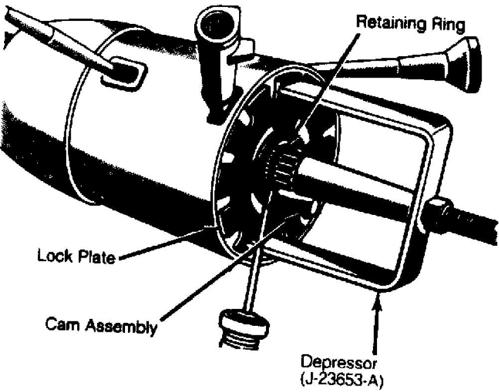
Fig. 9: Installing Lock Plate Retaining Ring Courtesy of Chrysler Corp.
Install steering wheel. See STEERING WHEEL & HORN PAD R &
I under REMOVAL & INSTALLATION. Turn key/lock cylinder to OFF
position, move ignition switch downward to eliminate lash, and install
switch retaining screws. Tighten screws to 35 INCH lbs. (4 N.m).
Depress dimmer switch slightly and insert 3/32" drill bit
into adjustment hole. Loosen retaining screws, move switch upward to
remove lash, and retighten screws to 35 INCH lbs. (4 N.m). Remove
drill bit and test dimmer switch operation in all column tilt
positions.
Install steering column. See appropriate type column
under REMOVAL & INSTALLATION. Reconnect negative battery cable. Test
ignition switch in all tilt positions. Ensure vehicle starts only in
Park and Neutral.
TORQUE SPECIFICATIONS
CHEROKEE
TORQUE SPECIFICATIONS (CHEROKEE)
Application
Ft. Lbs. (N.m)
Column Mounting Bracket Bolt 15 (20)
Flexible Coupling Bolt 25 (34)
Steering Wheel Retaining Nut 25 (34)
INCH Lbs. (N.m)
Bearing Housing-To-Lock Housing Screw 35 (4)
Column Clamp Stud 20 (2)
Column Clamp Stud Nut 106 (12)
Dimmer Switch 35 (4)
Hazard Switch Knob Screw 27 (3)
Housing Cover Screw 100 (11)
Ignition Switch Screw 35 (4)
Lock Housing-To-Jacket Screw 90 (10)
Shift Tube Support Screw 60 (7)
Steering Column Lower Bracket Bolt 106 (12)
Tilt Release Spring Retaining Screw 35 (4)
Toe Plate 66 (7)
Turn Signal Retaining Plate Screw 33 (4)
GRAND CHEROKEE & GRAND WAGONEER
TORQUE SPECIFICATIONS (GRAND CHEROKEE & GRAND WAGONEER)
Application Ft. Lbs. (N.m)
Flexible Coupling Bolt 25 (34)
Intermediate Shaft Pinch Bolt 35 (47)
Steering Wheel Retaining Nut 45 (61)
INCH Lbs. (N.m)
Bearing Housing-To-Lock Housing Screw 35 (4)
Column Clamp Stud 20 (2)
Column Clamp Stud Nut 106 (12)
Dimmer Switch 35 (4)
Hazard Switch Knob Screw 27 (3)
Housing Cover Screw 100 (11)
Ignition Switch Screw 35 (4)
Lock Housing-To-Jacket Screw 90 (10)
Shift Tube Support Screw 60 (7)
Steering Column Lower Bracket Bolt 106 (12)
Tilt Release Spring Retaining Screw 35 (4)
Toe Plate 105 (12)
Turn Signal Retaining Plate Screw 33 (4)
Upper Bracket Nut 10 6 (12)
WRANGLER
TORQUE SPECIFICATIONS (WRANGLER)
Application Ft. Lbs. (N.m)
Column Mounting Bracket Bolt 21 (28)
Flexible Coupling Bolt 25 (34)
Steering Wheel Retaining Nut 25 (34)
INCH Lbs. (N.m)
Bearing Housing-To-Lock Housing Screw 35 (4)
Column Clamp Stud 20 (2)
Column Clamp Stud Nut 106 (12)
Dimmer Switch 35 (4)
Hazard Switch Knob Screw 27 (3)
Housing Cover Screw 100 (11)
Ignition Switch Screw 35 (4)
Lock Housing-To-Jacket Screw 90 (10)
Shift Tube Support Screw 60 (7)
Steering Column Lower Bracket Bolt 106 (12)
Tilt Release Spring Retaining Screw 35 (4)
Toe Plate 192 (22)
Turn Signal Retaining Plate Screw 33 (4)