Ā
1993 Jeep Cherokee
1983-98 GENERAL INFORMATION
Emission Control Visual Inspection Procedures
All Models
* PLEASE READ THIS FIRST *
This article is provided for general information only. Not all information applies to all makes and models. For more complete information, see appropriate article(s) in the ENGINE PERFORMANCE Section.
EMISSION CONTROL LABELS
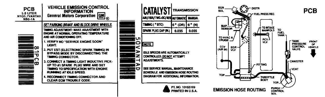
The vehicle manufacturerÆs emission control label, also known as the underhood tune-up label or VehicleÆs Underhood Emission Control System (VECI) label, is located in the engine compartment. Information regarding year model of vehicle, engine size, number of cylinders, emission equipment or type, engine tune-up specifications, whether vehicle was manufactured for sale in California or is a Federal vehicle, vacuum hose routing schematic, etc., can be found on this label. See Fig. 1.
In addition to the VECI label, some emission control
inspection and maintenance programs may require an additional label to be affixed to the vehicle in special circumstances. For example, in California, a Bureau Of Automotive Repair (BAR) engine label may be affixed to the left door post. A BAR engine label is only used when the vehicle has an engine change, approved modification or is a Specially Constructed (SPCN) or an acceptable Gray market vehicle. Check your stateÆs emission control inspection and maintenance laws to determine if a similar label is used.
THIS VEHICLE CONFORMS TO U.S. EM REGULATIONS APPLICABLE TO 1W2 MOOEL-VEU NEW PASSENGER CARS AND IS CERTIFIED FOR SALE IN CALIFORNIA. (OBD EXEMPT)
93D04127
Fig. 1: Typical Emission Control Label Courtesy of General Motors Corp.
EMISSION CONTROL VISUAL INSPECTION
* PLEASE READ THIS FIRST *
NOTE: The following emission control visual inspection procedures
should be used as a guide only. When performing a visual inspection, always follow your stateÆs recommended
inspection procedures.
A visual inspection is made to determine if any required emission control devices are missing, modified or disconnected. Missing, modified or disconnected systems must be made fully operational before a vehicle can be certified.
POSITIVE CRANKCASE VENTILATION (PCV)
PCV controls the flow of crankcase fumes into the intake manifold while preventing gases and flames from traveling in the opposite direction. PCV is either an open or closed system. See Fig. 2
Ensure PCV system is installed as required. Verify valve, required hoses, connections, flame arresters, etc., are present, routed properly and in serviceable condition.
 Fig. 2:
OPEN SYSTEM
Typical Open & Closed Type PCV System
THERMOSTATIC AIR CLEANER (TAC)
The TAC supplies warm air to air intake during cold engine operation. This system is active during cold engine warm-up only. Under all other operating conditions, air cleaner function is the same as any non-thermostatic unit.
Ensure required exhaust shroud, hot air duct, vacuum hoses and air cleaner components are present and installed properly. See Fig. 3. Ensure any required thermostatic vacuum switches are in place and vacuum hoses are installed and in serviceable condition. Also ensure air cleaner lid is installed right side up. Check for oversized air filter elements and for additional holes in the air cleaner housing.
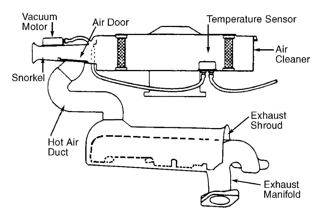 Fig. 3:
93F04133
Typical Thermostatic Air Cleaner System
FUEL EVAPORATIVE SYSTEM (EVAP)
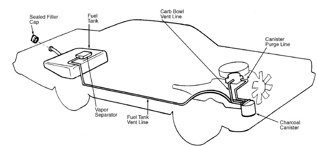
The EVAP system allows for proper fuel system ventilation while preventing fuel vapors from reaching the atmosphere. This means that vapors must be caught and stored while the engine is off, which is when most fuel evaporation occurs. When the engine is started, these fuel vapors can be removed from storage and burned. In most systems, storage is provided by an activated charcoal (or carbon) canister. See Fig. 4. On a few early systems, charcoal canisters are not used. Instead, fuel vapors are vented into the PCV system and stored inside the crankcase.
The main components of a fuel evaporation system are a sealed fuel tank, a liquid-vapor separator and vent lines to a vapor-storing canister filled with activated charcoal. The filler cap is normally not vented to the atmosphere, but is fitted with a valve to allow both pressure and vacuum relief.
Although a few variations do exist between manufacturers, basic operation is the same for all systems. Check for presence of vapor storage canister or crankcase storage connections when required. Ensure required hoses, solenoids, etc., are present and connected properly. Check for proper type fuel tank cap. Check for any non-OEM or auxiliary fuel tanks for compliance and the required number of evaporation canisters.
93H04134
Fig. 4: Typical Fuel Evaporative System
CATALYTIC CONVERTERS
Oxidation Catalyst (OC)
This type of converter is the most common. It may use pellets or monolith medium, depending upon application. See Fig. 5. Platinum and palladium (or platinum alone) are used as catalyst in this type of converter.
Visually check for presence of catalytic converter(s). Check for external damage such as severe dents, removed or damaged heat shields, etc. Also check for pellets or pieces of converter in the tailpipe.
 Baffle
Exhaust Gas In
Converter Shell
Catalyst Coated Pellets
Baffle
Exhaust Gas Out
93A04135
Fig. 5: Typical Oxidation Catalytic Converter (Pellet Type) Typical Three-Way Catalytic Converter Is Similar Courtesy of General Motors Corp.
Shown;
Three-Way Catalyst (TWC)
This type of converter is nearly identical to a conventional
converter with the exception of the catalyst. See Fig. 5. The TWC converter uses rhodium, with or without platinum, as its catalyst. Rhodium helps reduce NOx emissions, as well as HC and CO.
Visually check for presence of catalytic converter(s). Also check for presence of any required air supply system for the oxidizing section of the converter. Check for external damage such as severe dents, removed or damaged heat shields, etc. Check for pellets or pieces of converter in the tailpipe.
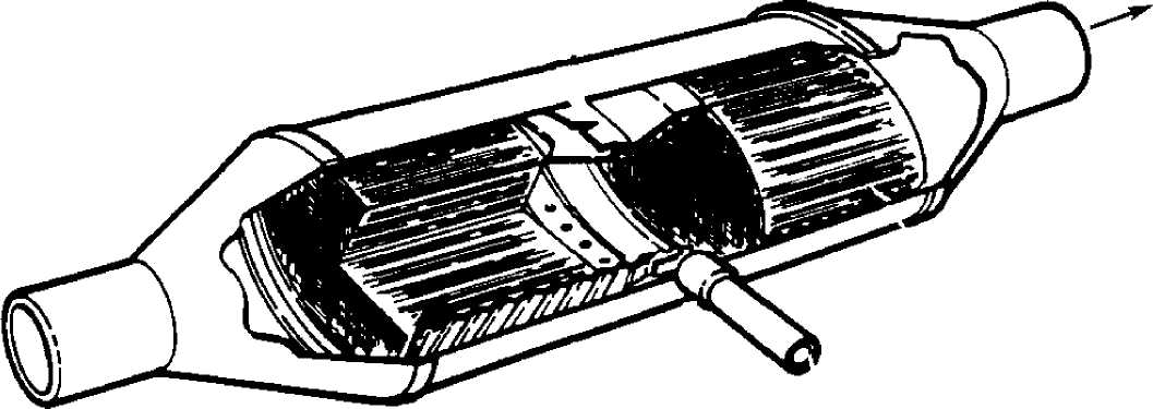
Three-Way Catalyst + Oxidation Catalyst (TWC + OC) This system contains a TWC converter and an OC converter in a common housing, separated by a small air space. See Fig. 6. The 2 catalysts are referred to as catalyst beds. Exhaust gases pass through the TWC first. The TWC bed performs the same function as it would as a separate device, reducing all 3 emissions. As exhaust gases leave the bed, they pass through the air space and into the second (OC) converter catalyst bed.
Visually check for presence of catalytic converter(s). Check for external damage such as severe dents, removed or damaged heat shields, etc. Check for pellets or pieces of converter in the tailpipe.
93C04136
Fig. 6: Typical Three-Way + Oxidation Catalytic Converter Courtesy of General Motors Corp.
FILL PIPE RESTRICTOR (FR)
A fuel tank fill pipe restrictor is used to prohibit the introduction of leaded fuel into the fuel tank. Unleaded gasoline pump dispensers have a smaller diameter nozzle to fit fuel tank of vehicle requiring the use of unleaded fuel (vehicles equipped with catalytic converter).
Visually inspect fill pipe restrictor(s) for tampering, i.e., restrictor is oversize or the flapper is non-functional. If vehicle is equipped with an auxiliary fuel tank, ensure auxiliary fuel tank is also equipped with a fill pipe restrictor.
EXHAUST GAS RECIRCULATION (EGR) SYSTEM
Single Diaphragm EGR Valve
This type uses a single diaphragm connected to the valve by a shaft. Diaphragm is spring-loaded to keep valve closed in the absence of vacuum. As throttle valves open and engine speed increases, vacuum is applied to the EGR vacuum diaphragm, opening the EGR valve. This vacuum signal comes from a ported vacuum source. Variations in the vacuum signal control the amount of exhaust gas that is recirculated. See Fig. 7.
Verify EGR valve is present and not modified or purposely damaged. Ensure thermal vacuum switches, pressure transducers, speed switches, etc., (if applicable) are not by-passed or modified. Ensure vacuum hose(s) to EGR valve is not plugged.
NO VACUUM SIGNAL
93E04137
Fig. 7: Typical Single Diaphragm EGR Valve Courtesy of General Motors Corp.
Dual Diaphragm EGR Valve
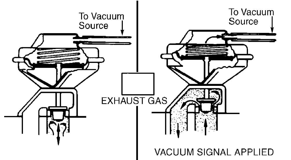
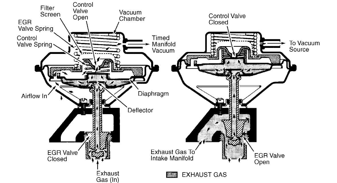
This type uses 2 diaphragms with different effective areas and 2 vacuum sources. Although similar to the single diaphragm type, the second diaphragm is added below the upper diaphragm and is rigidly attached to the valve seat. See Fig. 8. These diaphragms form a vacuum chamber which is connected to manifold vacuum.
During highway cruising when manifold vacuum is high in the center chamber, manifold vacuum tends to pull the valve closed. However, the vacuum signal applied to the top side of the upper diaphragm overcomes the downward spring force and the manifold vacuum pull, due to the diaphragmÆs larger piston. This regulates the amount of EGR.
When manifold vacuum is low during acceleration, the higher vacuum signal opens the valve, permitting more EGR. When manifold vacuum is high during highway cruising, the valve is only partially opened, reducing the amount of EGR.
Verify EGR valve is present and not modified or purposely damaged. Ensure thermal vacuum switches, pressure transducers, speed switches, etc., (if applicable) are not by-passed or modified. Ensure vacuum hose(s) to EGR valve is not plugged.
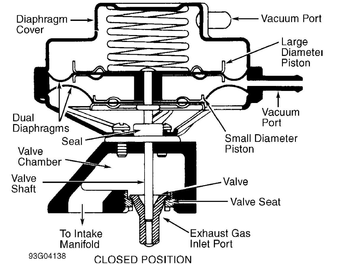
Fig. 8: Typical Dual Diaphragm EGR Valve Courtesy of General Motors Corp.
Positive Backpressure EGR (BP/EGR) Valve
This type uses both engine vacuum and exhaust backpressure to control the amount of EGR. It provides more recirculation during heavy engine loads than the single diaphragm EGR valve.
A small diaphragm-controlled valve inside EGR valve acts as a pressure regulator. The control valve gets an exhaust backpressure signal through the hollow valve shaft. This exhaust backpressure exerts a force on bottom of control valve diaphragm. The diaphragm plate contains 6 bleed holes to bleed air into the vacuum chamber when backpressure valve is in open position. See Fig. 9.
Verify EGR valve is present and not modified or purposely damaged. Ensure thermal vacuum switches, pressure transducers, speed
switches, etc., (if applicable) are not by-passed or modified. Ensure vacuum hose(s) to EGR valve is not plugged.
93104139
Fig. 9: Typical Positive Backpressure EGR Valve Courtesy of General Motors Corp.
Negative Backpressure EGR (BP/EGR) Valve
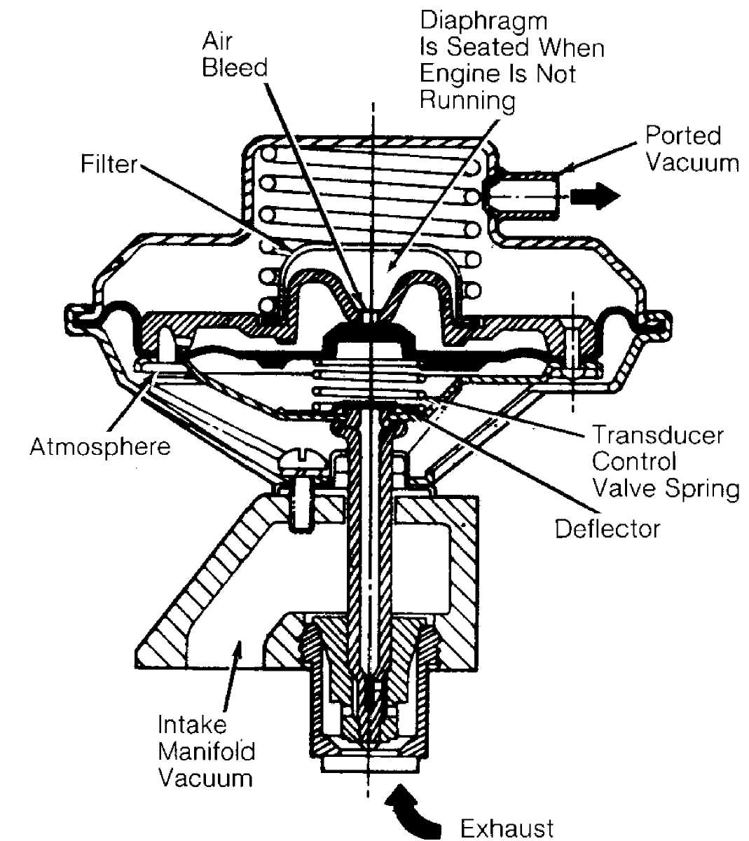
This type has the same function as the positive BP/EGR valve except valve is designed to open with a negative exhaust backpressure. The control valve spring in the transducer is placed on the bottom side of the diaphragm. See Fig. 10.
When ported vacuum is applied to the main vacuum chamber, partially opening the valve, the vacuum signal from the manifold side (reduced by exhaust backpressure) is transmitted to the hollow stem of the valve. See Fig. 10. This enables the signal to act on the diaphragm, providing a specific flow. Thus, the EGR flow is a constant percentage of engine airflow.
Verify EGR valve is present and not modified or purposely damaged. Ensure thermal vacuum switches, pressure transducers, speed switches, etc., (if applicable) are not by-passed or modified. Ensure vacuum hose(s) to EGR valve is not plugged.
93A04140
Fig. 10: Typical Negative Backpressure EGR Valve Courtesy of General Motors Corp.
Digital EGR Valve
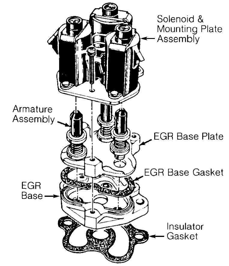
The digital EGR valve operates independently of engine manifold vacuum. This valve controls EGR flow through 3 orifices.
These 3 orifices are opened and closed by electric solenoids. The solenoids are, in turn, controlled by the Electronic Control Module (ECM). When a solenoid is energized, the armature with attached shaft and swivel pintle is lifted, opening the orifice. See Fig. 11.
The ECM uses inputs from the Coolant Temperature Sensor (CTS), Throttle Position Sensor (TPS) and Mass Airflow (MAF) sensors to control the EGR orifices to make 7 different combinations for precise EGR flow control. At idle, the EGR valve allows a very small amount of exhaust gas to enter the intake manifold. This EGR valve normally operates above idle speed during warm engine operation.
Verify EGR valve is present and not modified or purposely damaged. Ensure thermal vacuum switches, pressure transducers, speed switches, etc., (if applicable) are not by-passed or modified. Ensure vacuum hose(s) to EGR valve is not plugged. Ensure electrical connector to EGR valve is not disconnected.
93C04141
Fig. 11: Typical Digital EGR Valve Courtesy of General Motors Corp.
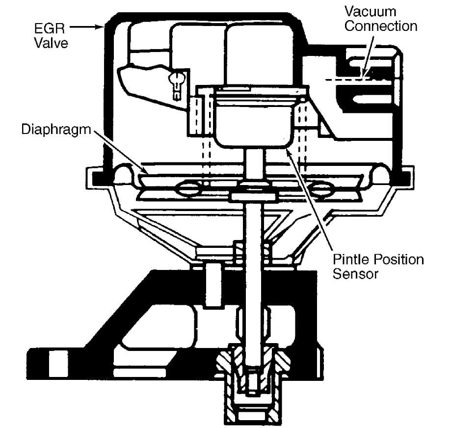
Integrated Electronic EGR Valve
This type functions similar to a ported EGR valve with a
remote vacuum regulator. The internal solenoid is normally open, which causes the vacuum signal to be vented off to the atmosphere when EGR is not controlled by the Electronic Control Module (ECM). The solenoid valve opens and closes the vacuum signal, controlling the amount of vacuum applied to the diaphragm. See Fig. 12.
The electronic EGR valve contains a voltage regulator, which converts ECM signal and regulates current to the solenoid. The ECM controls EGR flow with a pulse width modulated signal based on airflow, TPS and RPM. This system also contains a pintle position sensor, which works similarly to a TPS sensor. As EGR flow is increased, the sensor output increases.
Verify EGR valve is present and not modified or purposely damaged. Ensure thermal vacuum switches, pressure transducers, speed switches, etc., (if applicable) are not by-passed or modified. Ensure electrical connector to EGR valve is not disconnected.
93E04142
Fig. 12: Cutaway View Of Typical Integrated Electronic EGR Valve Courtesy of General Motors Corp.
SPARK CONTROLS (SPK)
Spark control systems are designed to ensure the air/fuel mixture is ignited at the best possible moment to provide optimum efficiency and power and cleaner emissions.
Ensure vacuum hoses to the distributor, carburetor, spark delay valves, thermal vacuum switches, etc., are in place and routed properly. On Computerized Engine Controls (CEC), check for presence of required sensors (O2, MAP, CTS, TPS, etc.). Ensure they have not been tampered with or modified.
Check for visible modification or replacement of the feedback carburetor, fuel injection unit or injector(s) with a non-feedback carburetor or fuel injection system. Check for modified emission-related components unacceptable for use on pollution-controlled vehicles.
AIR INJECTION SYSTEM (AIS)
Air Pump Injection System (AP)
The air pump is a belt-driven vane type pump, mounted to engine in combination with other accessories. The air pump itself consists of the pump housing, an inner air cavity, a rotor and a vane assembly. As the vanes turn in the housing, filtered air is drawn in through the intake port and pushed out through the exhaust port. See Fig. 13.
Check for missing or disconnected belt, check valve(s), diverter valve(s), air distribution manifolds, etc. Check air injection system for proper hose routing.
 BLACK ARROWS - NORMAL FLOW
CROSS HATCHED ARROWS - BY-PASS CONDITION
Deceleration By-Pass
93G04143
Fig. 13: Typical Air Pump Injection System Courtesy of General Motors Corp.
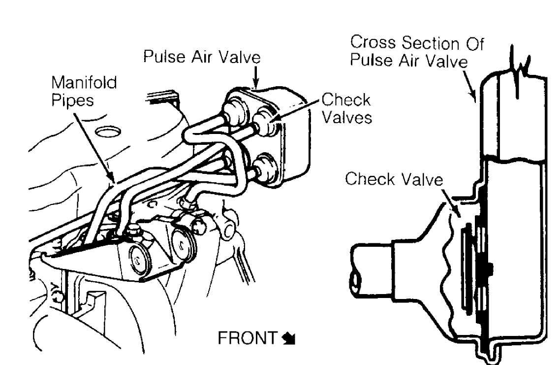
Pulsed Secondary Air Injection (PAIR) System PAIR eliminates the need for an air pump and most of the associated hardware. Most systems consists of air delivery pipe(s), pulse valve(s) and check valve(s). The check valve prevents exhaust gases from entering the air injection system. See Fig. 14.
Ensure required check valve(s), diverter valve(s), air distribution manifolds, etc., are present. Check air injection system for proper hose routing.
93104144
Fig. 14: Typical Pulsed Secondary Air Injection System Courtesy of General Motors Corp.
OXYGEN SENSOR (O2)
The O2 sensor is mounted in the exhaust system where it monitors oxygen content of exhaust gases. Some vehicles may use 2 O2 sensors. The O2 sensor produces a voltage signal which is proportional to exhaust gas oxygen concentration (0-3%) compared to outside oxygen (20-21%). This voltage signal is low (about .1 volt) when a lean mixture is present and high (1.0 volt) when a rich mixture is present.
As ECM compensates for a lean or rich condition, this voltage signal constantly fluctuates between high and low, crossing a reference voltage supplied by the ECM on the O2 signal line. This is referred to as cross counts. A problem in the O2 sensor circuit should set a related trouble code.
COMPUTERIZED ENGINE CONTROLS (CEC)
The CEC system monitors and controls a variety of
engine/vehicle functions. The CEC system is primarily an emission control system designed to maintain a 14.7:1 air/fuel ratio under most operating conditions. When the ideal air/fuel ratio is maintained, the catalytic converter can control oxides of nitrogen (NOx), hydrocarbon (HC) and carbon monoxide (CO) emissions.
The CEC system consists of the following sub-systems:
Electronic Control Module (ECM), input devices (sensors and switches) and output signals.
EARLY FUEL EVAPORATION (EFE)
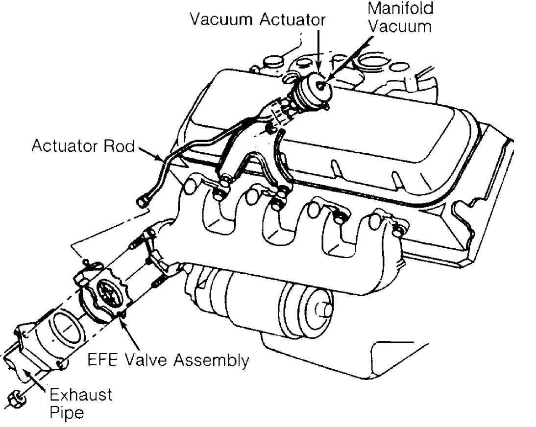
The EFE valve is actuated by either a vacuum actuator or a bimetal spring (heat-riser type). The EFE valve is closed when engine is cold. The closed valve restricts exhaust gas flow from the exhaust manifold. This forces part of the exhaust gas to flow up through a passage below the carburetor. As the exhaust gas quickly warms the intake mixture, distribution is improved. This results in better cold engine driveability, shorter choke periods and lower emissions.
Ensure EFE valve in exhaust manifold is not frozen or rusted in a fixed position. On vacuum-actuated EFE system, check EFE thermal vacuum valve and check valve(s). Also check for proper vacuum hose routing. See Fig. 15.
93B04145
Fig. 15: Typical Vacuum-Actuated EFE System Courtesy of General Motors Corp.
EMISSION MAINTENANCE REMINDER LIGHT (EMR) (IF EQUIPPED)
If equipped, the EMR light (some models may use a reminder flag) reminds vehicle operator that an emission system maintenance is required. This indicator is activated after a predetermined time/mileage.
When performing a smog check inspection, ensure EMR indicator is not activated. On models using an EMR light, light should glow when ignition switch is turned to ON position and should turn off when engine is running.
If an EMR flag is present or an EMR light stays on with engine running, fail vehicle and service or replace applicable emission-related components. To reset an EMR indicator, refer to appropriate MAINTENANCE REMINDER LIGHTS in the MAINTENANCE section.
MALFUNCTION INDICATOR LIGHT (MIL)
The Malfunction Indicator Light (MIL) is used to alert vehicle operator that the computerized engine control system has detected a malfunction (when it stays on all the time with engine running). On some models, the MIL may also be used to display trouble codes.
As a bulb and system check, malfunction indicator light will glow when ignition switch is turned to ON position and engine is not running. When engine is started, light should go out.