SEATS - POWER
1988 Jeep Cherokee
1988 Power Seats JEEP
Cherokee, Wagoneer, Grand Wagoneer
DESCRIPTION
A 3 armature permanent magnet reversible motor is coupled through cables to rack and pinion assemblies, located in the tracks. This system provides 6 different movement directions. Circuit is protected by a 30-amp circuit breaker on the fuse block.
TESTING
PRELIMINARY CHECKS
Ensure battery is fully charged and all electrical
connections are clean and tight. Turn on dome light. Apply switch to the inoperative position. If dome light dims, seat motion is attempting to function, indicating mechanical failure. Check and repair as necessary. If dome light does not dim, proceed with the following tests.
HARNESS VOLTAGE
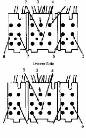
Disconnect switch harness connector, located under seat. Connect ground lead of test light to terminal No. 2. Touch other lead of test light to terminal No. 1. See Fig. 1. If test light comes on, circuit is good. If test light does not come on, check circuit breaker and harness. If harness and circuit breaker checks good, perform drive motors check.
 7 8
15
Passenger Side
Fig. 1: Seat Switch Terminal Identification Courtesy of Chrysler Motors.
DRIVE MOTORS
Rear Motor
Disconnect switch harness connector. Connect a covered jumper wire between terminal No. 1 and 5. See Fig. 1. Connect a second covered jumper wire between terminal No. 2 and 6. If motor does not operate, reverse jumper wire at terminal No. 5 and 6. If motor still does not operate, either harness or complete 3 motor assembly is defective.
Center Motor
Disconnect switch harness connector. Connect a covered jumper wire between terminal No. 1 and 3. See Fig. 1. Connect a second covered jumper wire between terminal No. 2 and 4. If motor does not operate, reverse jumper wire at terminal No. 3 and 4. If motor still does not operate, either harness or complete 3 motor assembly is defective.
Front Motor
Disconnect switch harness connector. Connect a covered jumper wire between terminal No. 1 and 7. See Fig. 1. Connect a second covered jumper wire between terminal No. 2 and 8. If motor does not operate, reverse jumper wire at terminal No. 7 and 8. If motor still does not operate, either harness or complete 3 motor assembly is defective.
NOTE: No further testing information is available from manufacturer.
REMOVAL & INSTALLATION
MOTOR
CAUTION: Use care to avoid bending drive cables during removal.
NOTE: Whenever maintenance of motor, cable and housing assemblies or transmissions is necessary, they must be synchronized to ensure easy and proper operation. Refer to manufacturer for proper procedure.
Removal & Installation
Remove seat assembly. Lay seat assembly on its back. Remove motor mounting screws. Disconnect housings and cables from motor assembly and remove motor. To install, reverse removal procedure.