2.5L CEC SYSTEM
1988 Jeep Cherokee
1988 Computerized Engine Controls
JEEP 4-CYLINDER 2.5L TBI COMPUTERIZED EMISSION CONTROL
Cherokee, Comanche
DESCRIPTION
áThe computerized engine control system, used on 2.5L models
with throttle body fuel injection, is built around an electronic
control unit (ECU). The ECU is a microprocessor-based computer.
áThe major function of the system is to reduce emissions. It
accomplishes this through a series of 13 sensors or switches that
constantly monitor several engine conditions. See Fig. 16.
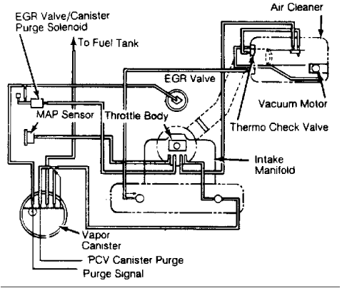
Fig. 1: Vacuum Diagram for Jeep 2.5L CEC System
áThe computer processes input information from the sensors to
get an accurate picture of engine operation. It then provides output
control signals to regulate air/fuel ratio, ignition, idle speed and
emission control devices. This permits optimum engine performance
with minimum emissions.
OPERATION
áThe engine control system is divided into 6 sub-systems:
electronic control unit (also called the ECU or computer), sensors and
switches, fuel control, emission control, idle speed control, and
ignition advance control.
ELECTRONIC CONTROL UNIT (ECU)
áThe ECU is located under the instrument panel, above the
accelerator pedal. It receives information from the 13 engine sensors
or switches to determine engine operating conditions at any particular
moment. The ECU responds to these signals by sending a control signal
to the fuel injector, fuel pump, ignition control module, idle speed
actuator (ISA) motor, EGR solenoid, and canister purge solenoid. It
also controls the Load Swap relay, and on Man. Trans. models, the up
shift indicator lamp.
SENSORS & SWITCHES
áExhaust Gas Oxygen (EGO) Sensor
áThe amount of oxygen in exhaust gases varies according to the
air/fuel ratio of the intake charge. The exhaust gas oxygen sensor,
located in the exhaust pipe, detects this content and transmits a low
voltage signal to the ECU.
áThe outer surface of the sensor is exposed to exhaust gases,
the inner surface to outside air. The difference in the amount of
oxygen contacting the inner and outer surfaces of the sensor creates
a
pressure, which results in a small voltage signal. This signal, which
is a measure of the unburned oxygen in the exhaust gas, is transmitted
to the ECU.
áIf the amount of oxygen in the exhaust system is low (rich
mixture), the sensor voltage signal will be high. If the mixture is
lean, the oxygen sensor will generate a low voltage signal.
áThe sensor has a heating element that keeps the sensor at
proper operating temperature during all operating modes.
áManifold Air/Fuel Temperature (MAT) Sensor
áThe manifold air/fuel temperature sensor is installed in the
intake manifold. This sensor provides a voltage signal to the ECU
representing the temperature of the air/fuel mixture in the intake
manifold. The ECU compensates for air density changes during high
temperature operation.
áCoolant Temperature Sensor (CTS)
áThe coolant temperature sensor is located in the intake
manifold coolant jacket. This sensor provides a voltage signal to the
ECU. The ECU uses this signal to determine engine temperature. During
cold engine operation, the ECU responds by enriching the air/fuel
mixture delivered to the injector, compensating for fuel condensation
in the intake manifold, controlling engine warm-up speed, increasing
ignition advance, and inhibiting operation of the EGR system.
áManifold Absolute Pressure (MAP) Sensor
áThe MAP sensor detects absolute pressure in the intake
manifold as well as ambient atmospheric pressure. This information is
supplied to the ECU, through voltage signals, as an indication of
engine load. The sensor is attached to the plenum chamber near the
hood latch. A vacuum line from the throttle body supplies the sensor
with manifold pressure information.
áKnock Sensor
áThe knock (detonation) sensor, located in the cylinder head,
provides an input signal to the ECU whenever detonation occurs. The
ECU then retards ignition advance to eliminate the detonation at the
applicable cylinders.
áSpeed Sensor
áThe speed sensor (or crankshaft position sensor) is mounted
at the flywheel/drive plate housing. The sensor detects the flywheel/
drive plate teeth as they pass during engine operation and sends an
electrical signal to the ECU, which calculates engine speed.
áThe flywheel/drive plate has a large trigger tooth and notch
..
located 90 and 12 small teeth before each top dead center (TDC)
position. When a small tooth or notch pass the magnetic core in the
sensor, the build-up and collapse of the magnetic field induces
a
small voltage signal in the sensor pick-up windings.
áThe ECU counts these signals representing the number of teeth
as they pass the sensor. When a larger trigger tooth and notch pass
the magnetic core, a higher voltage signal is sent to the ECU. This
indicates to the ECU that a piston will be at the TDC position 12
teeth later. The ECU either advances or retards ignition timing as
necessary according to sensor inputs.
áBattery Voltage
áBattery voltage input to the ECU ensures that proper voltage
is applied to the injector. The ECU varies voltage to compensate for
battery voltage fluctuations.
áStarter Motor Relay
áThe engine starter motor relay provides an input to the ECU,
indicating the starter motor is engaged.
áWide Open Throttle (WOT) Switch
áThe WOT switch is mounted on the side of the throttle body.
The switch provides a voltage signal to the ECU under wide open
throttle conditions. The ECU responds to this signal by enriching the
air/fuel mixture delivered to the injector.
áClosed Throttle (Idle) Switch
áThis switch is integral with the idle speed actuator (ISA)
motor. The switch provides a voltage signal to the ECU, which
increases or decreases the throttle stop angle in response to engine
operating conditions.
áTransmission Gear Position Indicator
áThe gear position indicator is mounted on vehicles equipped
with automatic transaxles. It provides a signal to the ECU to
indicate that the transaxle is in a driving mode and not in Park or
Neutral.
áPower Steering Pressure Switch
áThe switch increases the idle speed during periods of high
power steering pump load and low engine RPM.
áA/C Switch
áThe A/C switch sends a signal to the ECU when the air
conditioner is operating and when the compressor clutch must be
engaged to lower the temperature. The ECU, in turn, increases engine
speed to compensate for the added load of the air conditioner.
FUEL CONTROL
An electric in-tank fuel pump supplies fuel through the fuel
filter located under the right rear floor pan to the throttle body,
maintaining a constant operating pressure. Fuel enters the fuel bowl
reservoir of the throttle body through the injector and overflow type
fuel pressure regulator. The fuel pump is controlled by the ECU.
A
ballast resistor attached to the right side of the plenum chamber,
reduces fuel pump speed after engine is running. The resistor is
by-passed in the "Start" position.
áThe fuel injector and fuel pressure regulator are integral
components of the throttle body. The injector is electronically
controlled by the ECU. See Fig. 15.
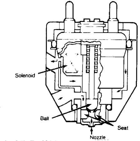
Fig. 2: Cross Section View of Injector
The fuel pressure regulator is a diaphragm-operated relief
.
valve which maintains fuel pressure of 17.3 psi (1.2 kg/cm ). See
Fig. 16. Fuel in excess of this pressure is returned to fuel tank by
a
fuel return line. The regulator is not controlled by the ECU. The
regulator's spring chamber is vented to the same pressure as the tip
of the injector.
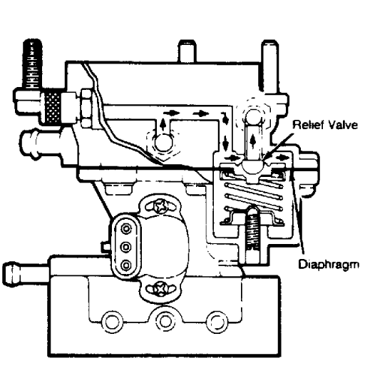
Fig. 3: Cross Section View of Fuel Pressure Regulator
áSince fuel pressure at the injector is kept constant, the
volume of fuel injected is dependent only on the length of time that
the injector is energized. The injection time duration is based on
engine operating conditions, which are provided to the ECU by the
input sensors. During engine start-up, the injector delivers an extra
amount of fuel to aid in starting.
EMISSION CONTROL
áBoth EGR and canister purge operation are regulated by the
ECU. Regulation of these 2 systems is accomplished through the use of
an electrically-operated vacuum solenoid.
áWhenever the solenoid is energized by the ECU, it prevents
vacuum action on the EGR valve and canister. The solenoid is
energized by the ECU during engine warm-up, improving cold
driveability. It is also energized during closed throttle (idle)
,
wide open throttle and during rapid acceleration or deceleration.
áIn this way the EGR is prevented from operating until the
engine reaches a predetermined temperature. The canister purge does
not operate until the oxygen sensor warms up and becomes operational.
This prevents an over-rich mixture until the oxygen sensor can
compensate for the extra fuel vapor.
IDLE SPEED ACTUATOR (ISA)
áThe ISA motor, located on the throttle body, is an
electrically-driven actuator that changes the throttle stop angle by
acting as a movable idle stop. The ECU commands the ISA to control
engine idle speed and maintain a smooth idle during sudden engine
deceleration. It does this by providing the appropriate voltage
outputs to produce the idle speed or throttle stop angle required for
the particular engine operating condition. There is no idle speed
adjustment.
áFor cold engine starting, the throttle is held open for
a
longer period to provide adequate engine warm-up prior to normal
operation. When starting a hot engine, the throttle is open for
shorter time.
áUnder normal engine operating conditions, engine idle is
maintained at a pre-programmed RPM, which may vary slightly due to
engine operating conditions. Under certain engine deceleration
conditions, the throttle is held slightly open.
IGNITION ADVANCE CONTROL
áUnder certain engine operating conditions, the predetermined
ignition advance curve is modified. This is accomplished through
2
switching circuits that connect the ECU and the ignition control
module.
ECU-CONTROLLED RELAYS
áSystem Power Relay
áLocated on the right strut tower, this relay is energized
during engine start up and remains energized until 3 to 5 seconds
after the engine is stopped. This permits the ECU to extend the idle
speed actuator for the next start up and then cease operation. See
Fig. 4.
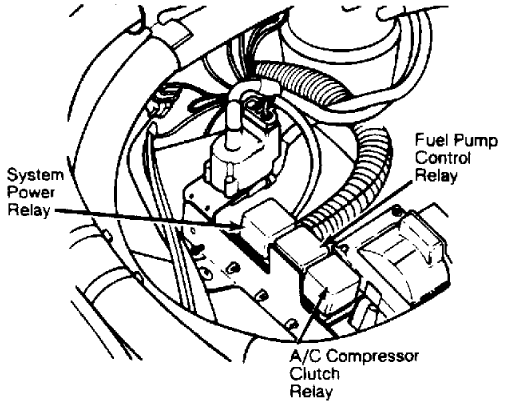
Fig. 4: Location of ECU-Controlled Relays
áLoad Swap Relay
áThe Load Swap Relay is used on models with A/C and power
steering. The relay works in conjunction with the power steering
pressure switch to disengage the A/C compressor clutch.
áIf the compressor clutch is engaged when the power steering
pressure switch contacts close, the input signal from the switch to
the ECU also activates the load swap relay. The relay contacts open,
cutting off electrical feed to the compressor clutch. The clutch
remains disengaged until the pressure switch contacts reopen and
engine idle returns to normal.
NOTE: The load swap relay does not reengage the compressor clutch
áimmediately. The relay has a timer that delays energizing
áthe clutch for .5 second to ensure smooth engagement.
áFuel Pump Control Relay
áBattery voltage is applied to the relay through the ignition
switch. The relay is energized when a ground is provided by the ECU.
When energized, voltage is applied to the fuel pump See Fig. 15.
áA/C Clutch Relay
The ECU controls the A/C compressor clutch by means of the
A/C clutch relay. See Fig. 15.
UP-SHIFT INDICATOR LAMP
áManual transaxle vehicles are equipped with an up-shift
indicator lamp. The lamp is normally turned on when the ignition
switch is turned "ON", and is turned off when the engine starts.
áThe lamp will again light during engine operation, according
to engine speed and load conditions. A switch, located on the
transaxle, prevents lamp from lighting when transmission is shifted
to the next highest gear. If the shift of gears is not performed, the
ECU will turn the lamp off after 3-5 seconds.
MODES OF OPERATION
IGNITION SWITCH "ON" MODE
áWhen the TBI system is activated by the ignition switch, the
system power relay is energized, and the fuel pump is energized by
the ECU through the fuel pump relay. The pump will operate for
approximately 1 second, unless the engine is operating or the starter
motor is engaged.
áThe ECU receives input from the CTS, MAT, and MAP sensors.
The up-shift indicator lamp is illuminated.
ENGINE START-UP MODE
áWhen the starter motor is engaged, the ECU receives inputs
from the CTS and speed sensors, the starter motor relay, and the wide
open throttle switch. The fuel pump is activated by the ECU and
voltage is applied to the injector, with the ECU controlling
injection time.
áThe ECU determines proper ignition timing from the speed
sensor input. If the wide open throttle switch is engaged, the ECU
will deactivate the injector to prevent flooding.
ENGINE WARM-UP MODE
áThe ECU receives inputs from the CTS, MAT, MAP, speed, and
knock sensors. It also is informed of throttle, gear (automatic
transaxle models) and A/C control position.
áThe ECU provides a ground for the injector, precisely
controlling fuel delivery to the engine. The ECU also controls
ignition timing, engine idle speed and throttle stop angle. On
vehicles with manual transmissions, the up-shift indicator lamp is
controlled according to engine speed and load.
CRUISE MODE
áDuring cruising speed, the ECU receives inputs from the CTS,
MAT, MAP, EGO, speed and knock sensors. It is also informed of
throttle, gear (automatic transaxle models), and A/C control position.
áThe ECU provides a ground to the injector, precisely
controlling injector time. It also controls idle speed, throttle stop
angle, ignition timing, air/fuel mixture ratio and up-shift indicator
lamp.
DECELERATION MODE
áDuring deceleration, the ECU receives inputs from the CTS,
MAT, MAP, EGO, speed and knock sensors. It also is informed of
throttle, gear (automatic transaxle models) and A/C control position.
áWhen the ECU receives deceleration input from the closed
throttle (idle) switch, it grounds the EGR valve/canister purge
solenoid. This interrupts vacuum to EGR valve and canister purge
function. The injector is grounded, and during rapid deceleration,
the ECU may stop injection for a short period of time. The ECU also
controls engine idle speed and throttle stop angle.
WIDE OPEN THROTTLE MODE
áDuring wide open throttle mode, the ECU receives inputs from
the CST, MAT, MAP, EGO, speed and knock sensors. It also monitors
throttle position.
áWhen the ECU receives deceleration input from the closed
throttle (idle) switch, it grounds the EGR valve/canister purge
solenoid. This interrupts vacuum to EGR valve and canister purge
function. The EGO sensor input is not accepted by the ECU. The
injector is grounded and amount of fuel is precisely controlled.
IGNITION SWITCH "OFF" MODE
áWhen ignition switch is turned "OFF", the ECU ceases to
provide ground for the injector and all fuel injection stops. The ECU
causes the idle speed actuator to fully extend for the next start up.
The ECU then deactivates.
COMPONENT TESTING
NOTE:
When test calls for volt-ohmmeter, use of a high impedance
digital type is required.
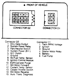
Fig. 5:
Diagnostic Connectors D1 and D2 Terminal Identification
á1) Disconnect wiring harness connector from the MAT sensor.
Test resistance of the sensor with an ohmmeter. If resistance is not
. .
185-100,700 ohms (3400 ohms at 70 F; 1600 ohms at 100 F), replace
sensor. With engine warm, resistance should be less than 1000 ohms.
á2) Connect one ohmmeter lead to sensor connector terminal.
Connect other lead, in turn, to ECU harness connector terminals 32
and 14. Repair wiring harness if resistance is greater than 1 ohm.
COOLANT TEMPERATURE SENSOR
á1) Disconnect wiring harness from CTS sensor. Test
resistance of sensor. If resistance is not 185-100,700 ohms (3400
...
ohms at 70 F; 1600 ohms at 100 F), replace sensor. With engine warm,
resistance should be less than 1000 ohms.
á2) Connect one ohmmeter lead to sensor connector terminal.
Connect other lead, in turn to ECU harness connector terminals 15 and
32. Repair wiring harness if an open circuit is indicated.
WIDE OPEN THROTTLE (WOT) SWITCH
á1) Disconnect wiring harness from WOT switch. Connect
ohmmeter leads to switch terminals, and manually open and close the
switch. When switch is closed, resistance should be infinite. A low
resistance should be indicated at wide open position. Test switch
operation several times. Replace WOT switch if defective. Reconnect
wiring harness.
á2) With ignition switch "ON", connect voltmeter between pin
6 and pin 7 (ground) of diagnostic connector D2. Voltage should be
zero with switch in wide open position and greater than 2 volts in
any other position.
á3) If voltage is always zero, test for short circuit to
ground in wiring harness or switch. Check for open circuit between
pin 8 of ECU connector and the switch connector. Repair or replace
wiring harness as necessary.
á4) If voltage is always greater than 2 volts, test for an
open wire or connector between the switch and ground. Repair as
required.
CLOSED THROTTLE SWITCH
NOTE: It is important that all testing be done with the idle speed
áactuator (ISA) motor plunger in the fully extended position
á(as it would be after a normal engine shut down). If it is
ánecessary to extend the motor plunger to test the switch, an
áISA motor failure can be suspected. Refer to ISA motor test.
á1) With ignition on, connect voltmeter positive lead to pin
13 of diagnostic connector D2. Attach negative lead to pin 7. Voltage
should be close to zero at closed throttle and greater than 2 volts
at any position other than closed throttle.
á2) If the voltage is always zero, test for a short circuit
to ground in the wiring harness or switch. Test for an open circuit
between pin 25 of ECU connector and throttle switch.
á3) If voltage is always more than 2 volts, test for an open
circuit in the wiring harness between the ECU and switch connector.
Also check for open circuit between the switch connector and ground.
Repair or replace wiring harness as needed.
MANIFOLD ABSOLUTE PRESSURE (MAP) SENSOR
á1) Inspect MAP sensor vacuum hose connections at sensor and
throttle body. Repair as required. Test MAP sensor output voltage at
MAP sensor connector pin B (as marked on sensor body) with the
ignition switch "ON" and engine off. See Fig. 15. Output voltage
should be 4.0-5.0 volts.
NOTE: Voltage should drop 0.5-1.5 volts with hot engine, at idle.

Fig. 6: MAP Sensor Terminal Identification
If markings on MAP sensor vary from illustration, use markings on
sensor.
á2) Test voltage at pin 33 of ECU connector for 4.0-5.0 volts
to verify wiring harness condition. Repair if required.
á3) With ignition on, check for MAP sensor supply voltage of
4.5-5.5 volts at sensor connector pin C. Similar voltage should be
present at pin 16 of ECU connector. Repair or replace wiring harness
if required. Test for sensor ground between pin 17 of ECU connector
and pin A of sensor connector.
á4) Using an ohmmeter, check for ground from pin 17 of ECU
connector to pin 2. If an open circuit is indicated, check for
a
defective sensor ground on the flywheel housing near the starter
motor.
á5) If ground is good, the ECU must be replaced. Before
replacing ECU, check to see if pin 17 of ECU connector is shorted to
12 volts. If so, correct the condition and test ECU before replacing.
Refer to the ELECTRONIC CONTROL UNIT TEST.
ELECTRONIC CONTROL UNIT
1) If all components have been checked and/or repaired, but
a system failure or problem still exists, the ECU may be at fault.
However, the ECU is a very reliable unit and must always be the final
component replaced if a doubt exists concerning the cause of a system
failure.
á2) The only way to confirm an ECU malfunction is to take the
unit to an AMC dealer to have it tested. This is the only sure way to
avoid replacing a good ECU.
SYSTEM DIAGNOSIS
PRELIMINARY CHECKS
áBe sure fuel is actually reaching the injector. Make sure no
air is entering the intake or exhaust system above the catalytic
converter. Before assuming an engine control system malfunction,
inspect the following systems to ensure components are in good
condition and are operating properly.
*
All support systems and wiring.
*
Battery connections and specific gravity.
*
Electrical and vacuum connections on components and sensors.
*
Emission control devices.
*
Ignition system.
*
Vacuum hoses.
CAUTION: Never connect or disconnect a component without turning the
áignition switch off. Never apply more than 12 volts or AC
ávoltage to system terminals. Disconnect battery cables
ábefore charging it. Remove ECU if temperatures are expected
...
to exceed 176 F (80 C), such as in a paint shop bake oven.
DIAGNOSTIC TEST CHARTS
áFollowing are 6 different diagnostic test flow charts,
providing the shortest means of testing the system. These include:
*
Ignition Switch "OFF" Chart - Tests system power for ECU
memory keep-alive voltage.
*
Ignition Switch "ON" Power Chart - Tests system power
function and fuel pump power function.
*
Ignition Switch "ON" Input Chart - Tests closed throttle
(idle) switch, wide open throttle (WOT) switch, manifold
absolute pressure (MAP) sensor, park/neutral switch, coolant
temperature sensor (CTS), manifold air/fuel temperature (MAT)
sensor and the respective switch or sensor circuits.
*
System Operational Chart - Tests engine start-up and fuel
injector circuits, plus function of closed loop air/fuel
mixture, coolant temperature sensor, manifold air/fuel
temperature sensor, knock sensor and closed loop ignition
retard/advance, EGR valve and canister purge solenoid, idle
speed actuator, and A/C control.
*
Basic Engine Chart - Indicates possible failures within other
engine related components.
*
Man. Trans. Up-shift Chart - Tests up-shift indicator lamp
function on manual transmission vehicles.
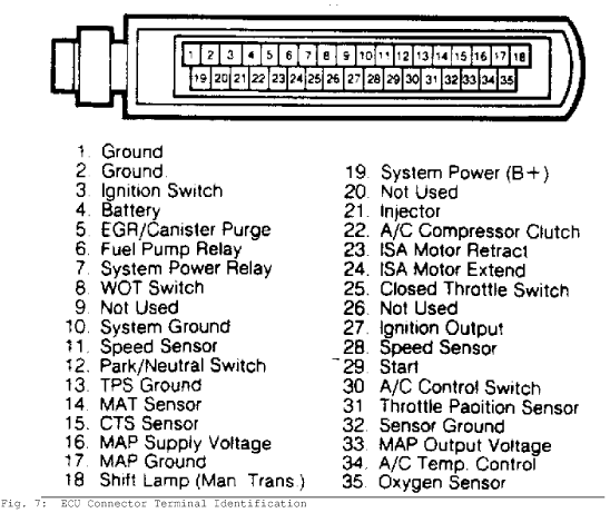
Fig. 7: ECU Connector Terminal Identification
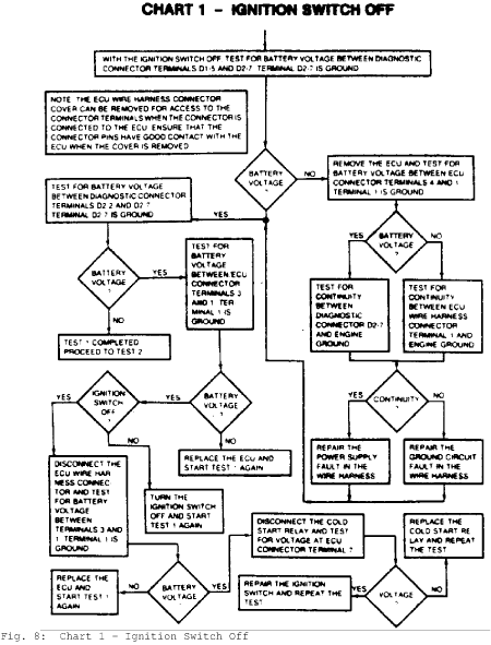
Fig. 8: Chart 1 - Ignition Switch Off
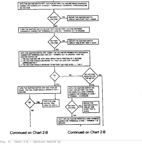
Fig. 9: Chart 2-A - Ignition Switch On
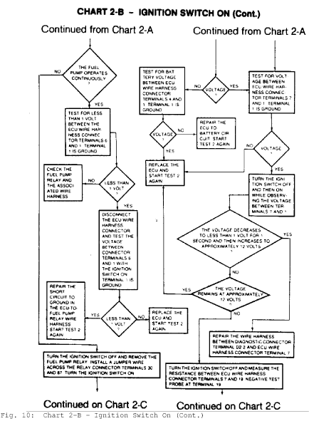
Fig. 10: Chart 2-B - Ignition Switch On (Cont.
)
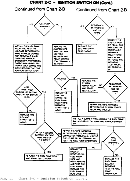
Fig. 11: Chart 2-C - Ignition Switch On (Cont.
)
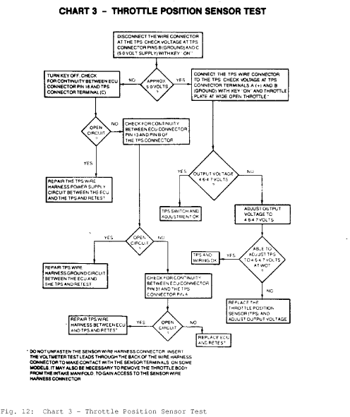
Fig. 12: Chart 3 - Throttle Position Sensor Test
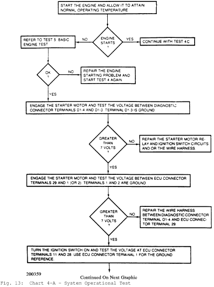
Fig. 13: Chart 4-A - System Operational Test
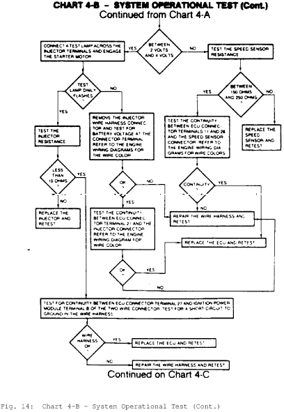
Fig. 14: Chart 4-B - System Operational Test (Cont.
)
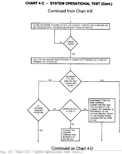
Fig. 15: Chart 4-C - System Operational Test (Cont.
)
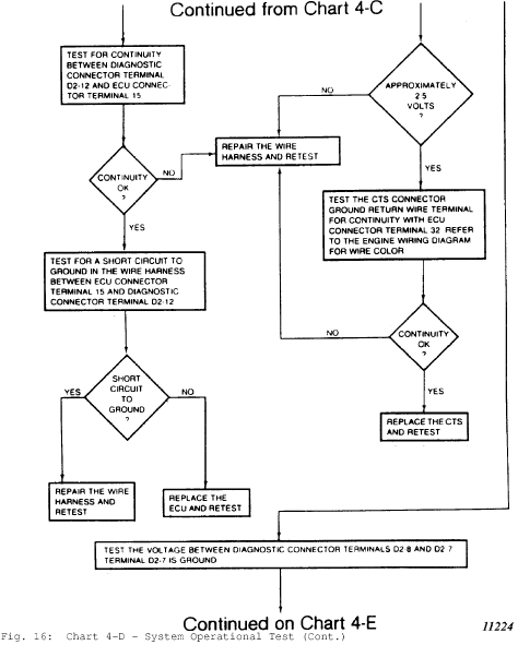
Fig. 16: Chart 4-D - System Operational Test (Cont.
)
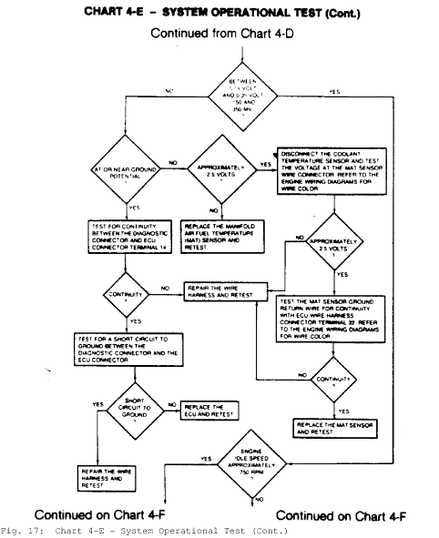
Fig. 17: Chart 4-E - System Operational Test (Cont.
)
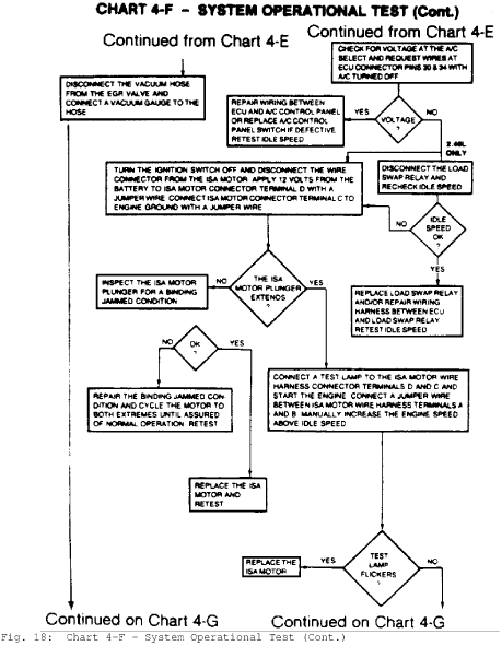
Fig. 18: Chart 4-F - System Operational Test (Cont.
)
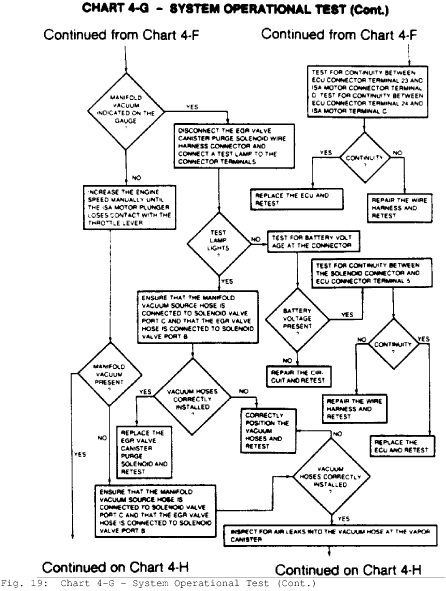
Fig. 19: Chart 4-G - System Operational Test (Cont.
)
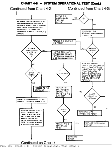
Fig. 20: Chart 4-H - System Operational Test (Cont.
)
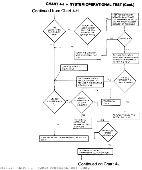
Fig. 21: Chart 4-I - System Operational Test (Cont.
)
F
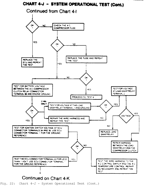
ig. 22: Chart 4-J - System Operational Test (Cont.
)
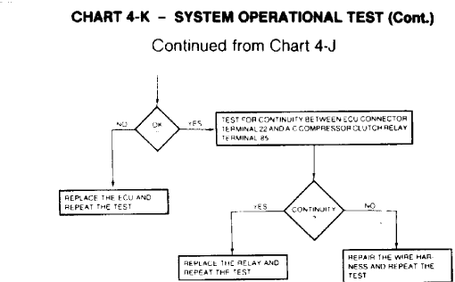
Fig. 23: Chart 4-K - System Operational Test (Cont.
)
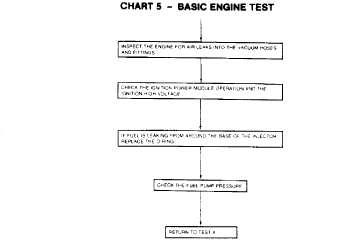
Fig. 24: Chart 5 - Basic Engine Test
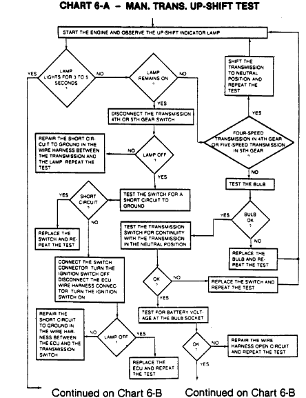
Fig. 25: Chart 6-A - Man. Trans. Up-Shift Test
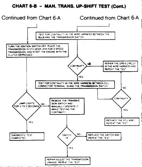
Fig. 26: Chart 6-B - Man. Trans. Up-Shift Test (Cont.
)
REMOVAL & INSTALLATION
THROTTLE BODY ASSEMBLY
áRemoval
á1) Remove throttle return spring, throttle cable and cruise
control cable, if equipped. Disconnect wiring harness connector from
injector, WOT switch, and ISA motor. Remove fuel supply and return
pipes from throttle body.
á2) Identify and tag vacuum hoses for installation later.
Disconnect vacuum hoses from throttle body assembly. Remove throttle
body-to-manifold retaining nuts from studs.
á3) Remove throttle body assembly from intake manifold. If
being replaced, transfer ISA motor and WOT switch and bracket
assembly to new throttle body.
áInstallation
áTo install, reverse removal procedure using a new gasket
between components. Adjust ISA motor and WOT switch.
FUEL INJECTOR
áRemoval
áRemove air cleaner assembly, injector wire connector, and
injector retainer clip screws. Using a pair of small pliers, gently
grasp center collar of injector (between electrical terminals), and
carefully remove injector with a lifting and twisting motion. Note
back-up ring fits over upper "O" ring.
áInstallation
á1) Lubricate new lower "O" ring with light oil and install
in housing bore. Lubricate new upper "O" ring with light oil and
install in housing bore. Install back-up ring over upper "O" ring.
á2) Position new injector in fuel body, and center nozzle in
lower housing bore. Seat injector with a pushing and twisting motion.
Align wire connector terminals properly. Install retainer clip and
screws. Connect injector wire connector.
FUEL PRESSURE REGULATOR
áRemoval
áRemove 3 retaining screws, securing pressure regulator to
fuel body. After noting location of components for reassembly
reference, remove regulator assembly.
áInstallation
áPosition pressure regulator assembly with a new gasket.
Install 3 retaining screws, securing regulator to throttle body.
Adjust regulator. Operate engine and inspect for leaks.
IDLE SPEED ACTUATOR, MOTOR & WIDE OPEN THROTTLE SWITCH
NOTE:
Closed throttle (idle) switch is integral with ISA and motor
assembly.
áRemoval
á1) Remove air cleaner assembly. Disconnect throttle return
spring, throttle cable and cruise control cable, if equipped.
Disconnect wiring harness connector from ISA motor and WOT switch.
á2) Remove ISA motor and WOT switch bracket from throttle
body. Remove motor-to-bracket retaining nuts. See Fig. 23. Do not
remove nuts from motor studs.
CAUTION: Do not attempt to remove ISA motor attaching nuts without
using a backup wrench on stud nuts. ISA motor internal
components may be dislodged if studs disengage and motor
cap comes off.

Fig. 27: ISA Motor and WOT Switch Removal
Bracket assembly is mounted on throttle body unit.
á3) To remove ISA motor from bracket, place backup 8 mm open
end wrench on ISA motor stud nuts to prevent studs from turning.
Grind wrench until thin enough to fit between motor and bracket.
Remove ISA motor attaching nuts. Remove 2 WOT switch-to-bracket
screws. Remove WOT switch.
áInstallation
á1) Install new WOT switch on bracket and tighten 2 screws.
Install ISA and motor on bracket. Install motor-to-bracket retaining
nuts. Install motor and WOT switch bracket assembly on throttle body.
á2) Connect wiring harness connector to ISA motor and WOT
switch. Connect the throttle return spring, throttle cable and cruise
control cable. Adjust ISA motor and WOT switch. Install air cleaner
assembly.
NOTE: After replacing or reinstalling the original ISA motor, be
ásure motor plunger is fully extended before starting the
áengine. If plunger is not fully extended, the closed
áthrottle switch may open prematurely, causing idle speed to
ádrop to approximately 400 RPM.
á3) Start engine with throttle at 1/4 open position. This
prevents ISA plunger from retracting. Stop engine. When ignition is
turned off, the motor plunger will fully extend. After installation
is complete, adjust ISA as required.
ELECTRONIC CONTROL UNIT
áRemoval & Installation
áLocate ECU in passenger compartment, below glove box. Remove
retaining screws and mounting bracket. Remove the ECU, and disconnect
wiring harness connector from ECU. Reverse removal procedure to
install.
OXYGEN SENSOR
áRemoval
áDisconnect the wire connector from sensor, and unscrew
sensor from exhaust pipe adapter. Clean adapter threads.
áInstallation
á1) Apply anti-seize compound to sensor threads. Do not allow
compound to adhere to any other part of sensor. Hand start the sensor
into place and tighten. Check that wire terminal ends are properly
seated in connector. Connect wire.
á2) Do not push the rubber boot over sensor body lower than
1/2" (13 mm) above base of sensor. If the sensor wire should break,
sensor must be replaced. These wires cannot be spliced or otherwise
repaired.
MANIFOLD AIR TEMPERATURE & MANIFOLD ABSOLUTE PRESSURE SENSORS
áRemoval & Installation
áDisconnect wiring harness connector from sensor. Disconnect
vacuum hose from MAP sensor. Remove sensor. Clean MAT sensor manifold
threads, and wrap with Teflon tape. To install, reverse removal
procedure.
COOLANT TEMPERATURE SENSOR (CTS)
áRemoval & Installation
áAllow engine to cool and release pressure from cooling
system. Remove wiring harness from sensor. Remove sensor at rear of
intake manifold, and plug hole to prevent excessive coolant loss. To
install, reverse removal procedure and replace lost coolant.
EGR VALVE & CANISTER PURGE SOLENOID
áRemoval & Installation
áDisconnect wiring harness and vacuum hose from solenoid.
Remove solenoid and bracket as an assembly. Replace solenoid as an
assembly. To install, reverse removal procedure.
ADJUSTMENTS
NOTE: The following adjustment procedures should not be necessary
áduring normal vehicle operation or maintenance. Adjustment
áof the listed components should only be required when
a
áfaulty component is replaced with a new one.
IDLE SPEED ACTUATOR (ISA) MOTOR
á1) With air cleaner removed, air conditioner off (if
equipped) and engine at normal operating temperature, connect
a
tachometer to terminals 1 (+) and 3 (-) of the small diagnostic
connector D1. See Fig. 16. Turn ignition off and observe ISA motor
plunger. The plunger should move to fully extended position.
á2) With ISA plunger fully extended, disconnect wire
connector and start engine. Engine speed should be 3300-3700 RPM. If
not, turn hex head screw on end of plunger until correct speed is
obtained.
á3) Hold closed throttle switch plunger all the way in while
opening throttle. Release the throttle. Throttle lever should not make
contact with the plunger. If contact is made, inspect throttle
linkage and/or cable for binding or damage. Repair as needed.
á4) Reconnect ISA motor wire connector and turn ignition off
for 10 seconds. Motor should move to fully extended position. Start
engine. Engine speed should be 3300-3700 RPM for a short time and
then fall to normal idle. Turn off engine and remove tachometer.
á5) When final adjustments have been made, apply thread
sealer to adjustment screw threads to prevent movement. Install air
cleaner.
WIDE OPEN THROTTLE SWITCH
á1) Remove the throttle body assembly from the engine, and
loosen 2 WOT switch retaining screws. Hold throttle in wide open
position, and attach a Throttle Angle Gauge (J-26701) to flat surface
of the throttle lever.
..
á2) Rotate scale to align the 15 mark with the pointer.
Level the gauge. Rotate scale to align zero with the pointer, and
close the throttle enough to center bubble. This positions the
..
throttle at 15 before wide open throttle.
3) Adjust the WOT switch lever on the throttle cam so that
..
the plunger is just closed at 15 position. Tighten the retaining
screws, and remove the gauge.
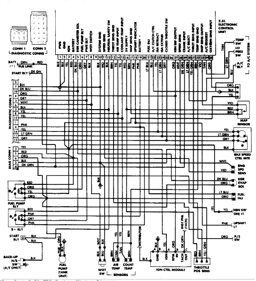
Fig. 28: Jeep 2.5L TBI System Wiring Diagram
FUEL PRESSURE REGULATOR
á1) Remove air cleaner assembly. Connect a tachometer to
terminals 1 and 3 of small diagnostic connector D1. Remove screw plug
and install special Fuel Pressure Test Fitting (8983 501 572)
.
2) Connect accurate fuel pressure gauge to fuel pressure
test fitting. Start engine and accelerate to 2000 RPM. Turn torx head
adjustment screw on bottom of fuel regulator to obtain 17.3 psi (1.2
kg/cm(C)) of fuel pressure.
NOTE:
Turning screw inward increases pressure; turning screw
outward decreases it.
á3) After specification is reached, install a lead seal ball
to cover regulator adjustment screw. Turn ignition switch off, and
disconnect tachometer. Disconnect fuel pressure gauge, remove test
fitting, and install original plug screw. Install air cleaner
assembly.