DEFOGGER - REAR WINDOW
1988 Jeep Cherokee
1988 Defoggers REAR WINDOW
Jeep: All Models
DESCRIPTION & OPERATION
System consists of 2 vertical bus bars and horizontal rows of heating elements fused to inside of glass, a control switch, an indicator light, and timer relay.
The grid feed wire is connected to bus bar on driver’s side of window. Ground bus bar is on right side of vehicle. Timer/relay receives current from fuse block. A circuit breaker protects defogger circuit.
NOTE: On some Jeep models, defogger switch and electric tailgate switch are serviced as an assembly.
TROUBLE SHOOTING
NOTE:
Control switch testing is not available for Wrangler models.
On Cherokee, Comanche and Wagoneer models, turn ignition
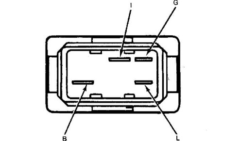
switch to "ON" position. Check for current at "I" and "B" terminals.
See Fig. 1. If there is no current, check circuit and repair as
necessary. Make sure that switch has a good ground through wire
connected to "G" terminal.
With a good ground circuit and ignition switch in "ON"
position, current should be present at "L" terminal. If there is no
current, replace control switch.

Fig. 1: Jeep Control Switch Terminals
3) On Grand Wagoneer models, turn ignition switch to "ON" position and press defogger switch. Separate wiring harness at connector under dash. Connect a 12-volt test light from Purple wire to
ground. Test light should light. Turn defogger switch to "OFF" position. Test light should not light.
GRID
Using a voltmeter with a 0-15 volt range, contact bus bar
connecting grid lines on passenger’s side of glass with negative lead
of voltmeter. Contact driver’s side bus bar with positive lead.
Turn ignition and control switches to "ON" position.
Reading should be 10-14 volts. Lower voltage indicates a poor ground.
Attach negative voltmeter lead to ground. Voltage reading should not
vary.
Contact negative lead to passenger’s side bus bar. Probe
each grid line at midpoint with positive lead. A 6-volt reading
indicates line is good. A zero volt reading indicates a break between
midpoint and driver’s side bus bar line.
A 10-14 volt reading indicates a break between midpoint
and passenger’s side bus bar line. Move positive lead toward break and
voltage will change when break is crossed.
NOTE:
On some Jeep models feed wire and ground wires a reversed.

Fig. 2: Grid Continuity Voltage Drop
RELAY
NOTE: No relay testing is available for Wrangler models.
1) On Grand Wagoneer models, attach negative lead of
voltmeter to ground. Probe Red wire at relay with voltmeter positive lead. Battery voltage should be indicated. If no voltage is indicated, operate tailgate window.
If window operates, wire between relay and window switch
is open. Probe Orange wire at relay with voltmeter positive lead. No
voltage should be indicated. Turn ignition switch to "ON" position.
Voltmeter should indicate voltage. If not, relay is defective or not
receiving voltage from Purple wire.
If relay operates properly, it should remain energized for
8 to 12 minutes before opening. If time period is too short or too
long, relay is defective. If relay did not energize, connect a jumper
wire to a 12-volt source in tailgate and probe Purple relay terminal.
If relay "clicks", trace Purple wire for open or short. If
relay does not click, check relay ground. If ground is okay, relay
should be replaced.