Throttle Cable Adjustment
Turn ignition switch to Off position.
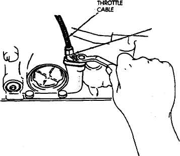
Fully retract cable plunger. Press cable button all
the way down. Then push cable plunger inward (Fig.
29).
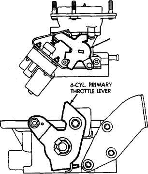
Rotate primary throttle lever to wide open throttle
position (Fig. 30).
Hold primary throttle lever in wide open position
and let cable plunger extend. Release lever when
plunger is fully extended. Cable is now adjusted.
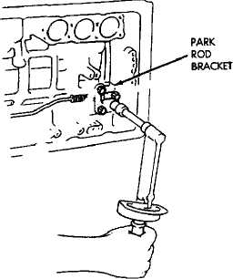
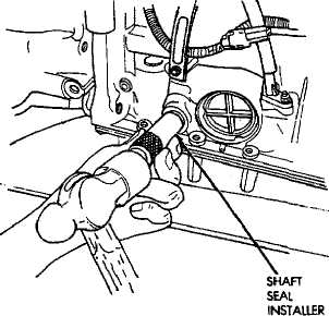
Fig. 24 Installing Manual Valve Shaft Seals
Fig. 26 Installing Park Rod Bracket

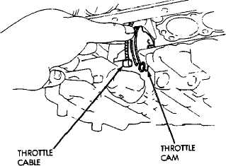
Fig. 25 Installing Spacer Sleeve On Sector
Fig. 27 Removing/Installing Throttle Cable
ACCUMULATOR PISTONS AND SPRINGS
Accumulator Piston and Spring Removal
Remove valve body .Refer to procedure in this sec
tion.
Remove accumulator pistons with compressed air
(Fig. 31). Apply air through small feed hole next to each
piston bore. Catch each piston in a shop towel as it exits
the bore.
CABLE BRACKET
CAUTION: Use only enough air pressure to ease each piston out of the bore. In addition, remove the pistons
one at a time and tag the pistons and springs for assembly reference. Do not intermix them.
*CYl. PRIMARY
THROTTLE
LEVER
Remove and discard piston O-ring seals. Then
clean the pistons and springs with solvent.
Inspect the pistons and springs and the piston
bores in the case. Replace worn damaged pistons. Re
place broken, collapsed or distorted springs. Replace the
case if the piston bores are damaged.
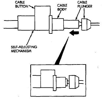
Fig. 28 Removing/Installing Cable And Bracket
Fig. 30 Rotate Primary Throttle Lever To Wide Open Position
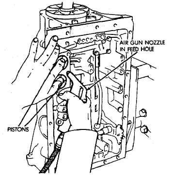
Fig. 31 Removing Accumulator Pistons
Fig. 29 Retract Throttle Cable Plunger 20 Fig. 31 Removing Accumulator PistonsInstall new O-ring seals on pistons. Lubricate seals
and pistons and piston bores with transmission fluid.
Install pistons and springs (Fig. 32).
Install valve body, oil screen and oil pan.
SECOND COAST BRAKE SERVO
Servo Overhaul
Remove valve body as outlined in this section.
Remove servo piston cover snap ring with snap
ring pliers (Fig. 33).
Remove servo piston and cover with compressed
air. Apply compressed air through oil hole in servo boss
to ease piston out of bore (Fig. 34).
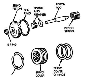
Remove and discard seal and O-rings from cover
and piston (Fig. 35). Inspect E-ring, piston, spring and
retainer, piston rod and piston spring. Replace worn or
damaged parts.
Install new seals on cover and piston.
Lubricate servo components with transmission
fluid.
Assemble and install servo components in case. Be
sure servo piston rod is properly engaged in the second
coast brake band.
Compress cover and piston and install cover snap
ring.
Install valve body, oil screen and oil pan.
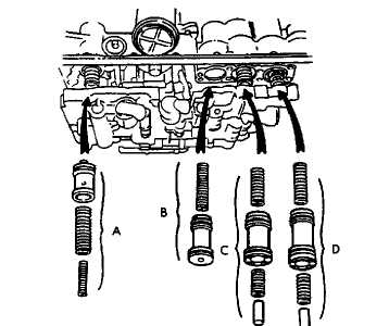
A. OVERDRIVE CLUTCH ACCUMULATOR PISTON AND SPRINGS
B. OVERDRIVE BRAKE ACCUMULATOR PISTON AND SPRINGS
Ń SECOND CLUTCH ACCUMULATOR PISTON, SPRINGS AND
SPACER
D. SECOND CLUTCH ACCUMULATOR PISTON, SPRINGS AND SPACER
NOTE: PISTON HEIGHT AND DIAMETER ARE OUTLINED IN THE SPECIFICATIONS SECTION.
PARK ROD AND PAWL
Park Rod and Pawl Removal
Remove valve body as outlined in this section.
Remove bolts attaching park rod bracket to case
(Fig. 36).
Remove park rod from manual valve shaft sector
(Fig. 37).
Remove park rod.
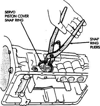
Fig. 33 Removing/Installing Servo Piston Cover Snap Ring
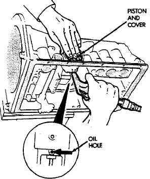
Fig. 32 Accumulator Piston-Springs-Spacers
21 Fig. 34 Removing Servo Cover And Piston
,
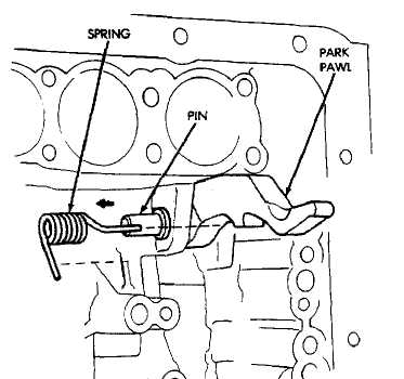
Remove park pawl, pin and spring (Fig. 38).
Examine park rod, pawl, pin and spring. Replace
any component that is worn or damaged.
Install pawl in case. Insert pin and install spring.
Be sure spring is positioned as shown in Figure 38.
Install park rod and bracket (Fig. 36). Tighten
bracket bolts to 10 N-m (7 ft-lbs) torque.
Install valve body, oil screen and oil pan as out
lined in this section.
EXTENSION/ADAPTOR HOUSING SEAL REPLACEMENT
(1) Raise vehicle.
SNAP RING
Fig. 35 Second Coast Brake Servo Components
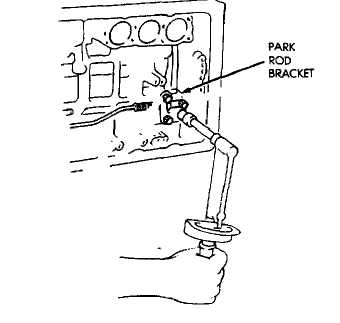
Fig. 37 Removing/Installing Park Rod
On 2WD or 4WD models, disconnect or remove
components necessary to gain access to the seal (e.g.
propeller shaft, crossmember, shift linkage, transfer
case, exhaust components, hoses, wires).
On 2WD models, remove seal from adaptor hous
ing (Fig. 39).
On 4WD model, remove dust shield and remove
seal from extension housing (Fig. 39).
Install new seal with appropriate size seal install
er. On 4WD models, also install dust shield.
Reinstall components removed to gain access to
seal.
Top off transmission fluid if necessary.

Fig. 36 Removing/Installing Park Rod Bracket 22 Fig. 38 Removing/Installing Park Pawl-Pin-Spring
SPEH)SENSOR
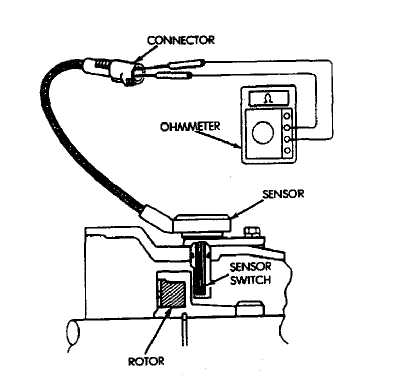
Speed Sensor Testing
Test the speed sensor with an ohmmeter. Place the ohmmeter leads on the terminals in the sensor connector (Fig. 40).
Rotate the transmission output shaft and observe the ohmmeter needle. The needle should deflect indicating the switch is opening/closing as the rotor moves past the sensor (Fig. 40). Replace the sensor if the ohmmeter does not display any kind of reading.
If a digital ohmmeter is being used, the sensor should generate an ohmmeter readout each time the switch opens and closes.
Speed Sensor Replacement
Disconnect sensor wire harness connector.
Remove sensor retainer bolt and remove sensor
(Fig. 41).
Remove and discard speed sensor O-ring.
Install new O-ring on speed sensor and install
sensor in transmission case.
Install sensor bracket and retainer bolt. Tighten
bolt to 7.4 N-m (65 in-lbs) torque.
Connect sensor wire harness connector.
SPEED SENSOR ROTOR-SPEEDOMETER DRIVE GEAR
Rotor-Drive Gear Removal
Raise vehicle.
Remove components necessary to gain access to
rotor and drive gear (e.g. propeller shaft, transfer case,
crossmember, shift linkage).
Disconnect speedometer cable and/or speed sensor.
Remove extension or adaptor housing.
Fig. 40 Speed Sensor Testing
Remove speedometer drive gear snap ring (Fig.
42).
Remove the speedometer drive gear and spacer (if
equipped).
Remove rotor by carefully prying it off output shaft
with wood dowel or hammer handle (Fig. 43).
Clean sealing surfaces of transmission case and
extension/adaptor housing.
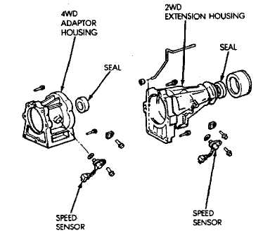

Fig. 39 Adaptor/Extension Housing Seals
23 Fig. 41 Speed Sensor Removal/Installation
Rotor-Drive Gear Installation
Install rotor, spacer (if equipped) and drive gear on
output shaft. Then install drive gear snap ring (Fig. 42).
Apply bead of RTV sealer, to transmission case
sealing surface and install extension/adaptor housing
on case.
Tighten extension/adaptor housing bolts to 34 ąm
(25 ft-lbs) torque.
Install components removed to gain access to rotor
and drive gear.
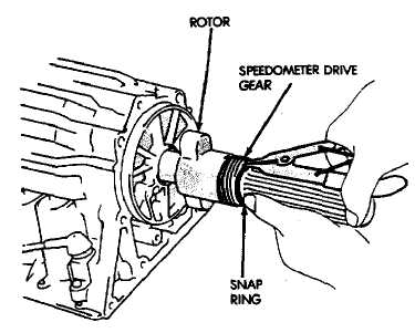
Fig. 42 Removing/Installation Speedometer Drive Gear

TPS SERVICE
A separate throttle position sensor is used for automatic transmission applications. The sensor is attached to the base of the throttle body. Refer to Group 14 for TPS service and adjustment.
SHIFT CABLE ADJUSTMENT
Shift transmission into Park.
Raise vehicle.
Release cable adjuster clamp to unlock cable (Fig.
47).
Unsnap cable from cable bracket (Fig. 47).
Move transmission shift lever all the way rear
ward into Park detent. Lever is on manual valve shaft
at left side of case.
Verify positive engagement of park lock by at
tempting tn rotate propeller shaft. Shaft will not rotate
when park lock is engaged.
Snap cable into cable bracket.
Lock shaft cable by pressing cable adjuster clamp
down until it snaps into place.
Check engine starting. Engine should start only in
Park and Neutral.
(10) Lower automobile.
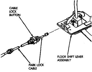
PARK LOCK CABLE ADJUSTMENT
Shift transmission into Park.
Turn ignition switch to Lock position.
Remove shift lever bezel and console screws. Raise
bezel and console for access to cable.
Pull cable lock button up to release cable (Fig. 48).
Pull cable forward. Then release cable and press
cable lock button down until it snaps in place.
Check adjustment as follows:
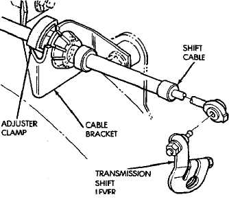
Fig. 43 Removing Speed Sensor Rotor
Fig. 47 Shift Cable Adjustment
Check movement of release shift handle but
ton (floor shift) or release lever (column shift). You
should not be able to press button inward or move
column lever.
Turn ignition switch to On position.
(e) Press floor shift lever release button or move column lever. Then shift into Neutral. If cable adjustment is correct, ignition switch can not be turned to Lock position. Perform same check with transmission in D range.
(7) Move shift lever back to Park and check ignition switch operation. You should be able to turn switch to Lock position and shift lever release button/lever should not move.
25
Fig. 48 Park Lock Cable
TRANSMISSION AND TORQUE CONVERTER REMOVAL
Raise vehicle.
Drain transmission fluid and reinstall oil pan
drain plug.
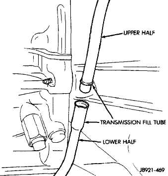
Remove upper half of transmission fill tube (Fig.
49).
Disconnect cooler lines at transmission. Cooler
lines have quick-disconnect fittings. Press fitting re
lease tabs and pull cooler line and fitting out of case.
Support engine with safety stand and support
transmission with jack.
Disconnect or remove following: transmission/
transfer case shift linkage; necessary exhaust compo
nents; speedometer cable; front/rear propeller shaft;
transmission wire harnesses; transfer case vacuum and
wire harnesses.
Remove rear crossmember.
Disconnect transmission throttle cable at engine.
Disconnect necessary vacuum and fluid hoses.
Fig. 49 Two-Piece Transmission Fill Tube
Remove starter motor.
Remove converter-to-drive plate bolts.
Remove converter housing-to-engine bolts.
Secure transmission (and transfer case assembly
on 4WD models) to transmission jack with safety
chains. Then remove transmission.
Remove torque converter if converter or oil pump
seal are to be serviced.
(15) Remove transfer case if transmission is to be
overhauled.
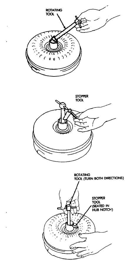
TORQUE CONVERTER STATOR CLUTCH INSPECTION
Insert rotating tool B.Vi. FM. 36 into converter
hub and seat tool in one-way clutch (Fig. 50).
Insert stopper tool B.Vi. FM. 37 in one converter
hub notch and into outer race of rotating tool.
Turn rotating tool clockwise. Converter clutch
should rotate freely and smoothly. Less than 2.5 N*m
(22 in-lbs) of torque should be required to rotate clutch
in clockwise direction.
Turn rotating tool in counterclockwise direction.
Converter clutch should lock.
Replace converter if clutch binds or will not lock.
OIL PUMP SEAL REPLACEMENT
Remove converter.
Remove old seal. Use blunt punch to collapse seal
and pry seal out of pump housing. Do not scratch or
damage seal bore.
Lubricate lip of new seal with petroleum jelly and
install seal in pump (Fig. 511.
Align and install torque converter.
TRANSMISSION AND TORQUE CONVERTER INSTALLATION
Mount transmission on transmission jack.
Install torque converter on transmission.
On 4WD models, install transfer case on trans
mission.
(41 Secure transmission (and transfer case assembly on 4WD models) to jack with safety chains.
(5) Align and position transmission and converter on
engine.
(6) Install converter housing-to-engine bolts.
(71 Install converter-to-drive plate bolts.
Install and connect starter motor.
On 4WD models, connect transfer case shift link
age and vacuum hoses.
(10) Connect exhaust components.
Install rear crossmember.
Connect speedometer cable and neutral switch
wires.
Align and connect front and rear propeller shafts.
Connect transmission wire harnesses and trans
fer case vacuum and wire harnesses.
Connect transmission cooler lines.
Connect transmission throttle valve cable at en
gine.
Install new O-ring seal on upper half of trans
mission fill tube. Then connect upper and lower tube
halves.
Lower vehicle.
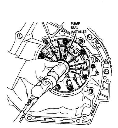
Fig. 51 Installing Oil Pump Seal
(19) Fill transmission with Mopar Mercon™ auto
matic transmission fluid.
Fig. 50 Checking Converter Clutch Operation