TRANSMISSION OVERHAUL
OVERHAUL SERVICE TOOLS
The special tools needed to overhaul the AW 4 transmission are provided in tool kit 6294 (B.Vi.FM. 23). However, ptessure test port adapter 7554 is not in-cludedin this kit and will have to be ordered separately. The overhaul tool kit and test port adapter are available through the parts division and dealer special tool program.
TRANSMISSION DISASSEMBLY
(1) Remove torque converter.
(2) Remove dipstick and both halves of oil filler tube.
(3) Remove clamp attaching wire harness and throttle pressure cable (Fig. 1) to transmission.
(4) Remove shift lever from manual valve shaft at left side of transmission.
Remove neutral switch.
Remove speedometer driven gear (if equipped) and
remove speed sensor (Fig. 2).
(7) Remuve converter housing bolts and remove housing (Fig. 3) from case.
(8) Remuve extension housing or adapter housing.
(9) On 2WD models, measure inside diameter of extension housing bushing with cylinder bore gauge or inside micrometer. Diameter should be 38.09 mm
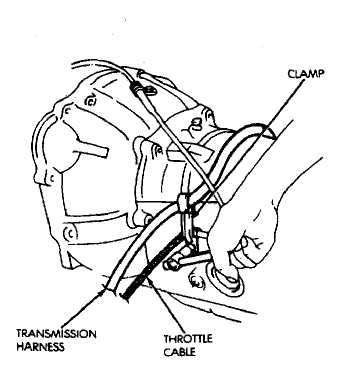
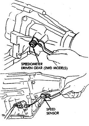
Fig. 2 Removing/Installing Speedometer Driven Gear And Speed Sensor
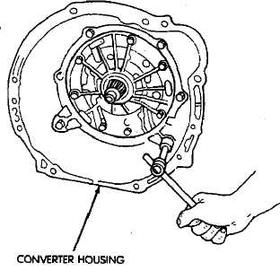
Fig. 1 Remove Harness And Cable Clamp
Fig. 3 Removing/Installing Converter Housing
(1.4996 in) or less. Replace housing as assembly if inside diameter exceeds specified limit.
Remove the speedometer drive gear snap ring
and remove the gear and gear spacer if equipped (Fig.
5).
Remove speed sensor rotor and key. Use wood
dowel or hammer handle to loosen and remove rotor
(Fig. 6).
Remove transmission oil pan, oil screen and
screen gaskets'(Fig. 7). Then mount transmission in
holding fixture.
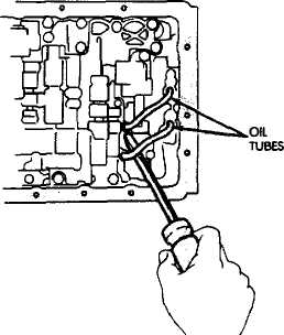
Remove valve body oil feed tubes (Fig. 8).
Disconnect solenoid wires (Fig. 9).
Remove harness bracket bolt and remove harness
and bracket Fig. 10).
Remove valve body bolts (Fig. 11).
Disconnect throttle cable from throttle cam (Fig.
12).
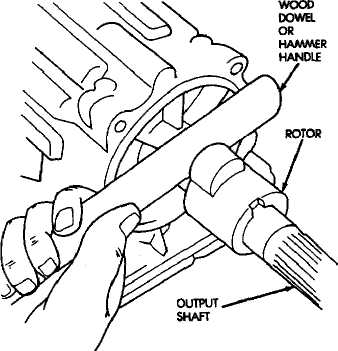
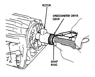
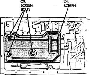
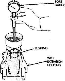
Fig. 4 Checking Bushing Diameter—2WD Extension Housing
Fig. 6 Removing Speed Sensor Rotor
Fig. 6 Removing Speed Sensor And Speedometer Drive Gear
Fig. 7 Removing Oil Screen
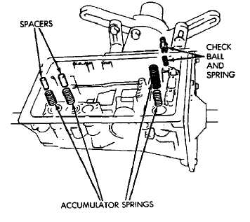
Remove valve body from case. Then remove ac
cumulator springs, spacers and check ball and spring
(Fig. 13).
Remove second brake and clutch accumulator
pistons with compressed air (Fig. 14). Apply air pres
sure through feed port and ease the pistons out of the
bore.
Remove overdrive brake accumulator piston with
compressed air (Fig. 14).
Remove overdrive clutch accumulator piston
with compressed air (Fig. 14).
Remove throttle cable.
Remove oil pump bolts and remove pump with
bridge-type puller B.Vi. FM. 25 (Fig. 15).
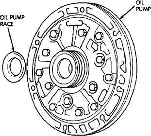
Remove race from oil pump (Fig. 16).
Remove fourth gear overdrive planetary gear and
overdrive direct clutch assembly (Fig. 17).
Remove race from fourth gear overdrive plane
tary (Fig. 18).
Remove thrust bearing, race and overdrive plan
etary ring gear (Fig. 19).
Measure stroke length of overdrive brake piston
as follows:
Mount dial indicator on case (Fig. 20).
Mount gauge tool B.Vi. FM. 35 so it contacts
piston (Fig. 20).
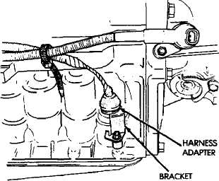
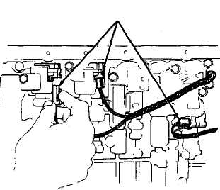
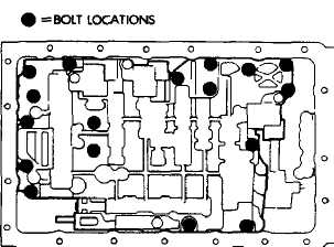
Fig. 8 Removing Valve Body Oil Tubes
SOLENOID WIRE CONNECTORS
Fig. 10 Removing Bracket And Harness
Fig. 9 Solenoid Wires
Fig. 11 Valve Body Bolt Locations
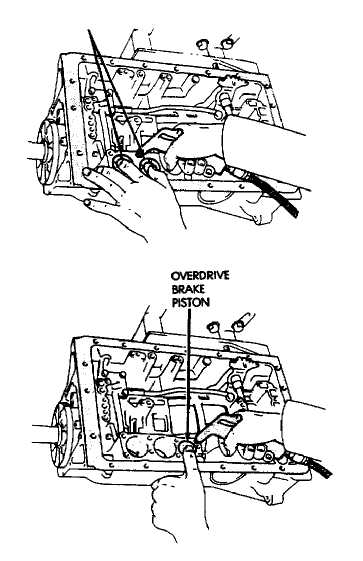
Apply 57-114 psi air pressure through piston
apply port and note piston stroke on dial indicator.
Stroke length should be: 1.40 -1.70 mm (.055 to .0699
in) on 6-tylinder models and 1.32 -1.62 mm (.0520 to
.0638 in) on 4-cylinder models.
If stroke is not within limits, replace brake
pack retainer. Select required retainer from Over
drive Brake Retainer Selection chart in Specifications
section.
Remove overdrive brake snap ring (Fig. 21).
Remove overdrive brake discs and plates (Fig.
221. Then measure disc thickness with a micrometer.
Minimum disc thickness is 1.84 mm (.0724 in). Replace
discs if thickness is less than specified.
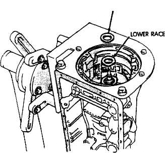
Remove overdrive support lower race (43) and
upper bearing and race assembly (Fig. 23).
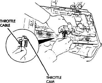
Fig. 12 Removing Throttle Cable
Remove overdrive support bolts (Fig. 24).
Remove overdrive support snap ring with tool
B.Vi. FM. 29 (Fig. 25).
SECOND BRAKE AND CLUTCH PISTONS
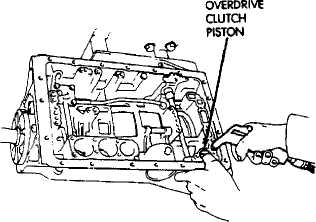
Fig. 13 Removing Accumulator Springs-Spacers-Check Ball
31 Fig. 14 Removing Accumulator Pistons
(34i Remove overdrive support (Fig. 261 with bridge-type puller tool B.Vi. FM. 25.
(35»Remove race from hub of overdrive support (Fig. 27).
(36) Measure stroke length of second coast brake piston rod as follows:
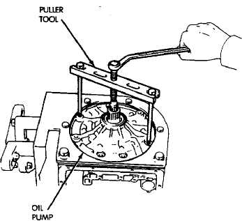
Fig. 15 Removing Oil Pump
Make reference mark on piston rod (Fig. 28) as
shown.
Apply 57-114 psi air pressure through piston
feed hole and check stroke length with gauge B.Vi.
FM. 40/41 (Fig. 28).
Stroke length should be 1.5-tc-3.0 mm (.059 to
.118 in).
If stroke length is incorrect, install new piston
rod and recheck stroke. If stroke is still incorrect,
replace second coast brake band.
Replacement piston rods are available in two
different lengths which are: 71.4 mm (2.811 in) and
72.9 mm (2.870 in).
(37) Remove second coast brake piston snap ring with tool B.Vi. FM. 29. Then remove piston cover and piston assembly with compressed air applied through piston feed hole (Fig. 29).
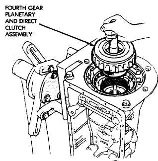
Fig. 17 Removing Fourth Gear Planetary And Direct Clutch Assembly
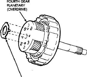
Fig. 16 Removing Oil Pump Race
32 Fig. 18 Remove Fourth Gear Planetary Race
(38) Disassemble second coast brake piston (Fig. 30). (41) Remove the second coast brake band E-ring from
i39l Remove direct and forward clutch assembly (Fig. band pin and remove brake band «Fig. 33).
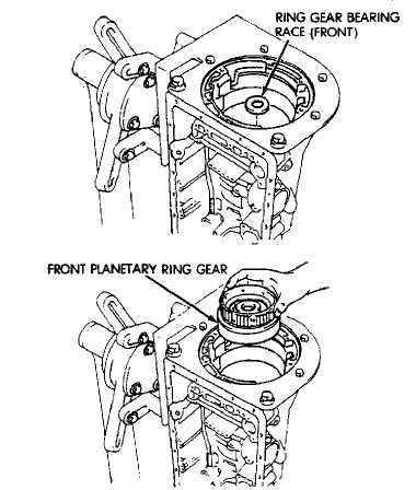
.Ä1 (42) Remove front planetary ring gear front bearing
(40) Remove thrust bearing and race from clutch hub race and remove front planetary ring gear (Fig. 34).
.Fig- 32).
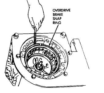
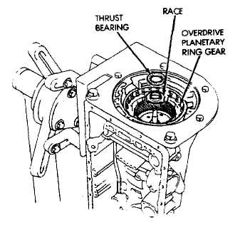
Fig. 21 Remove Overdrive Brake Snap Ring
Fig. 19 Remove Bearing, Race And Planetary Ring Gear
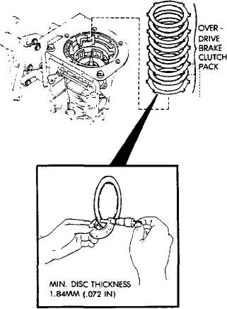
Fig. 22 Remove/Measure Overdrive Brake Disc Thickness
Fig. 22 Remove/Measure Overdrive Brake Disc
Fig. 20 Measuring Overdrive Brake Piston Stroke 33 Thickness
Remove thrust bearing and rear race from ring
gear (Fig. 35).
Remove planetary thrust race (Fig. 36).
Relieve load on planetary snap ring as follows:
Loosen transmission holding fixture. Turn transmis
sion over and allow output shaft to support transmis
sion weight. Place wood blocks under shaft to protect
splines (Fig. 36).
Remove planetary snap ring and remove plane
tary gear (Fig. 37).
Remove sun gear, input drum and one-way clutch
as assembly (Fig. 38).
Measure second brake clutch pack clearance (Fig.
39). Clearance should be: .62 to 1.98 mm (.0244 to .0780
in) on six-cyl. transmissions and .89 to 2.15 mm (.0350
UPPER BEARING AND RACE
to .0846 in) on four-cyl. transmissions. Replace discs if clearance is not within specifications.
Remove second brake clutch pack snap ring (Fig.
40).
Remove second brake clutch pack (Fig. 41). Mea
sure disc thickness with micrometer. Minimum thick
ness should be 1.84 mm (.0724 in). Replace discs if not
within specfications.
Remove bolts attaching park rod bracket to case.
Then disconnect park rod from manual shaft lever and
remove rod and bracket (Fig. 42).
Remove park pawl spring, pin and pawl (Fig. 43).
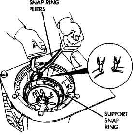
Fig. 25 Removing/Installing Overdrive Support Snap Ring
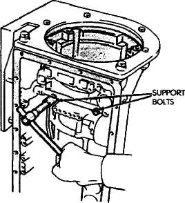 Fig. 23 Remove Overdrive Support Bearing/Races
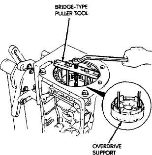
Fig. 26 Removing Overdrive Support
Fig. 24 Remove Overdrive Support Bolts 34 Fig. 26 Removing Overdrive Support(53) Measure clearance of first-reverse brake clutch pack (Fig. 44). Clearance should be: .70 to 2.00 mm (.0276 to .0787 in) îďá-cyl. transmissions and .60 to 1.74 mm (.0236 to .0685 in) on 4-cyl. transmissions. Replace discs if clearance is not as specified.
Remove second brake piston sleeve (Fig. 45).
Cover remover tool with tape to avoid damaging case.
Remove rear planetary gear, second brake drum
and output shaft as an assembly (Fig. 46).
Remove planetary and brake drum thrust bear
ing and race assembly (Fig. 47).
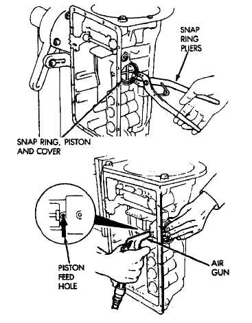
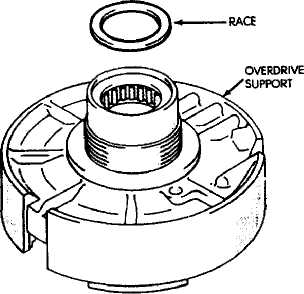
Fig. 27 Remove Overdrive Support Race
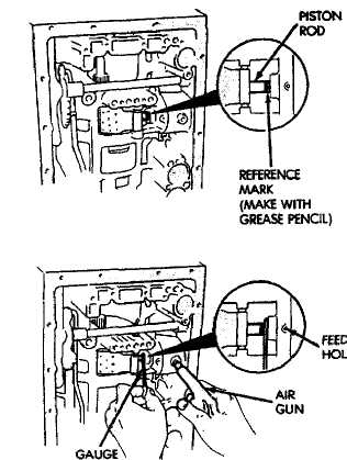
Fig. 28 Measuring Second Coast Brake Piston Rod Stroke
Fig. 29 Removing Second Coast Brake Cover And Piston
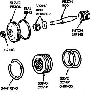
Fig. 30 Second Coast Brake Piston Components
(57) Remove second brake drum gasket from case with
gasket scraper or screwdriver (Fig. 48).
(58) Measure inside diameter of transmission case
rear bushing with bore gauge or inside micrometer (Fig.
49). Maximum allowable diameter is 38.18 mm (1.5031
inl. Replace transmission case if bushing I.D. is
greater than specified. Bushing is not serviceable.
CLEANING-INSPECTION
Clean the transmission components with solvent and dry them with compressed air only. Do not use shop towels or rags.
Blow compressed air through all oil feed passages and channels to be sure they are clear. Inspect the transmission components for wear and damage. Replace components that are damaged or worn beyond the limits specified in the individual overhaul procedures.
Replace all O-rings, gaskets and seals. These compo nents are not reusable. Also replace any snap ring that is distorted or damaged.
During overhaul assembly operations, lubricate the transmission components with Jeep or Mopar Mercon " automatic transmission fluid or petroleum jelly as indicated. Petroleum jelly should be used to prelubricate thrust bearings, washers and races. It can also be used to hold parts in position during assembly.
Soak replacement clutch and brake pack components in transmission fluid for at least 30 minutes before installation.
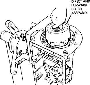
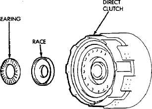
Fig. 32 Remove Bearing And Race From Clutch Hub
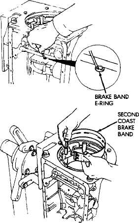
Fig. 33 Removing Second Coast Brake Band
Fig. 31 Removing Direct And Forward Clutch As
sembly 36
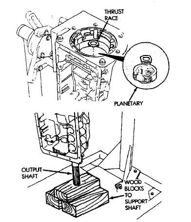
Fia. 36 Relieving Load On Planetary Snap Ring
Fig. 34 Removing Front Planetary Ring Gear Fig. 36 Relieving Load On Planetary Snap Ring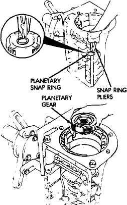
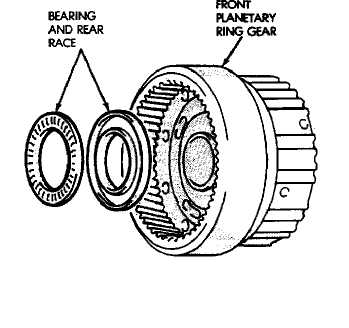
Fig. 35 Removing Ring Gear Bearing And Rear Race
Fig. 37 Removing Planetary Snap Ring And Gear
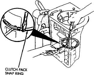
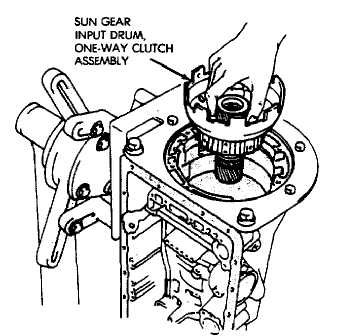
Fig. 40 Removing Second Brake Clutch Pack Snap Ring
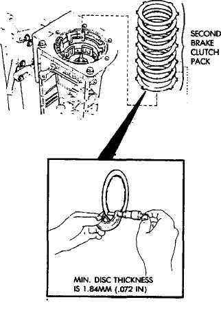
Fig. 38 Removing Sun Gear, Input Drum And One-Way Clutch
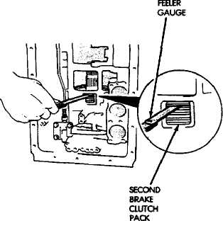
Fig. 39 Checking Second Brake Clutch Pack Clearance
38
Fig. 41 Remove/Measure Second Brake Clutch Disc Thickness
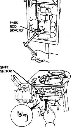
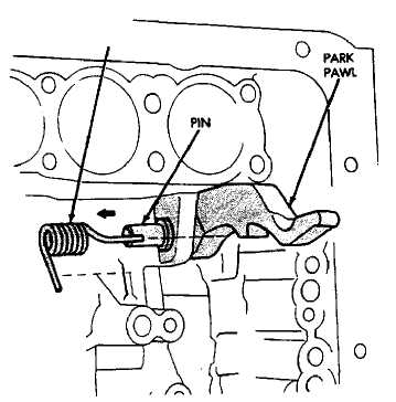 Fig. 42 Removing Park Rod And Bracket
SPRING 0
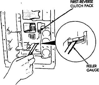
Fig. 44 Checking First-Reverse Brake Clutch Pack Clearance
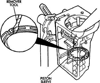
Fig. 45 Removing Second Brake Piston Sleeve
Fig. 43 Removing Park Pawl, Pin And Spring
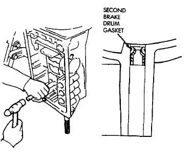
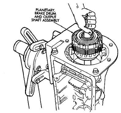
Fig. 48 Removing Brake Drum Gasket
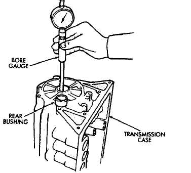
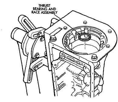
Fig. 46 Removing Rear Planetary, Second Brake Drum And Output Shaft
Fig. 49 Checking Rear Bushing Inside Diameter
Fig. 47 Removing Planetary And Brake Drum Thrust Bearing And Race Assembly
SUBASSEMBLY OVERHAUL AND TRANSMISSION ASSEMBLY
MANUAL VALVE SHAFT OVERHAUL
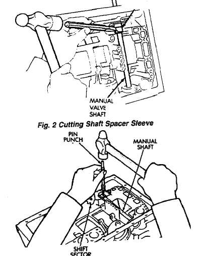
1 11 Remove shaft spacer sleeve in half with chisel and remove it from lever and shaft (Fig. 2).
(2) Remove shift sector retaining pin with pin punch
(Fig. 3).
(3) Pull shaft out of case and remove manual lever.
14) Carefully pry shaft seals from case.
PIN
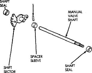
Fig. 1 Manual Valve Shaft Components
SPACER
Lubricate new seals with petroleum jelly and in
stall them in case (Fig. 4).
Install new spacer sleeve on shift sector (Fig. 5).
Install sector and sleeve on shaft and install shaft
in case.
Align sector and sleeve and install new retaining
pin.
Align notch in sleeve with depression in sector and
stake sleeve in two places. Be sure lever and shaft rotate
smoothly.
SEAL INSTALLER TOOL
Fig- 4 Installing Manual Shaft Seals
SLEEVE
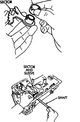
Fig. 3 Removing/Installing Sector Retaining Pin 41
Fig. 5 Installing Manual Shaft And Sector
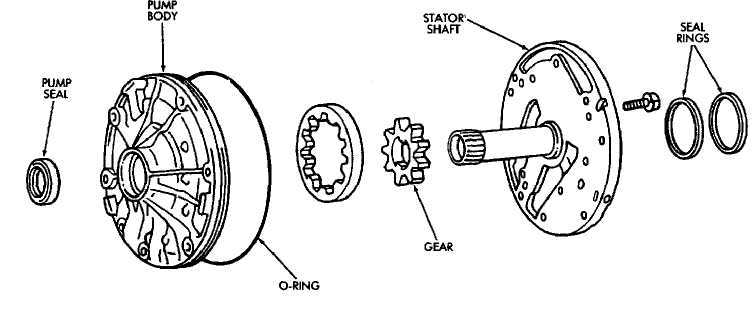
Fig. 1 Oil Pump Components
OIL PUMP OVERHAUL
Remove pump body O-ring (Fig. 1).
Remove pump seal rings (Fig. 1).
Remove bolts attaching stator shaft to pump body
and separate components.
Remove drive gear and driven gear from pump
body (Fig. 1).
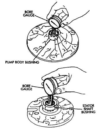
Measure inside diameter of pump body bushing
with bore gauge (Fig. 2). Diameter should be maximum
of 38.19 mm (1.5035 in). Replace pump body if bushing
I.D.- is greater than specified.
Measure inside diameter of stator shaft bushing
(Fig. 2). Take measurements at front and rear of bush
ing. Diameter should be maximum of 21.58 mm (.08496
in) at front and 27.08 mm (1.0661 in) at rear. Replace
stator shaft if bushing diameter is greater than speci
fied.
Measure oil pump clearances (Fig. 3).
Clearance between pump driven gear and pump body
should be maximum of .3 mm (.012 in).
Clearance between tips of pump gear teeth should be
maximum of .3 mm (.012 in).
Clearance between rear surface of pump housing and
pump gears should be maximum of 0.1 mm (.004 in).
Replace pump body and gears if any clearance is
greater than specified.
Remove old pump seal. Install new seal with in
staller tool B.Vi. FM. 38 (Fig. 4).
Lubricate and install gears in pump body.
Assemble stator shaft and pump body. Tighten
shaft-to-body bolts to 10 ąm (7 ft-lbs) torque.
Install new O-ring on pump body and new seal
rings on stator shaft.
Install pump in torque converter and check pump
gear rotation. Gears must rotate smoothly when turned
clockwise and counterclockwise.
Lubricate pump O-ring and seal rings with pe
troleum jelly.
Fig. 2 Checking Pump/Stator Shaft Bushings
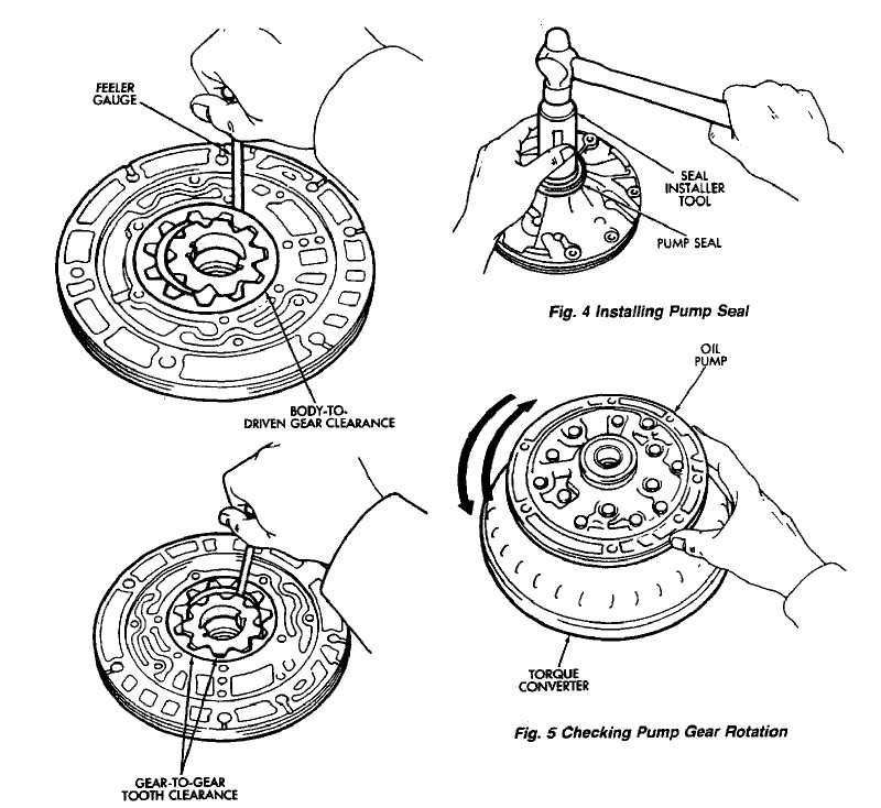
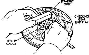
Fig.
3 Checking Pump Gear
Clearances 43