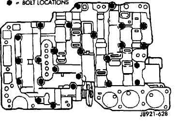
Fig. 5 Valve Body Bolt Locations
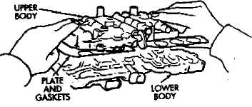
Fig. 6 Upper Body, Plate And Gaskets
Removing Upper Body From Lower Body
Remove two-piece detent spring (Fig. 3). Note po
sition of spring sections for assembly reference.
Remove manual valve from lower body (Fig. 4).
Remove bolts attaching upper body to lower body
(Fig. S).
Carefully lift and remove upper body, plate and
gaskets from lower body (Fig. 6).
Disassemble and overhaul upper and lower body
sections as outlined in following procedures.
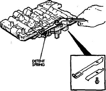
Fig. 3 Removing/Installing Detent Spring
LOWE» BODY
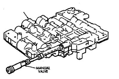
Fig. 4 Removing/Installing Manual Valve
Lower Body Disassembly
Remove check valve and spring, pressure relief
valve and spring and ball check and seat from lower
body. Note location of each valve for assembly refer
ence.
Remove the oil strainers (Fig. 2).
Note or mark position of valve retainers and pres
sure reducing plug clip for assembly reference. Do not
remove the retainers at this time.
Remove solenoid No. 1, 2 and 3. Discard solenoid
O-rings.
Remove release control valve retainer with mag
net and remove release control valve and plug (Fig. 4).
Remove 1-2 shift valve retainer and remove valve
plug, valve spring and valve (Fig. 5).
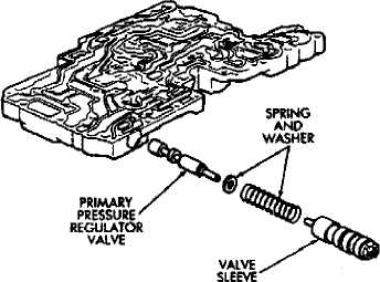
Remove primary regulator valve as follows:
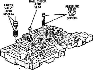
Fig. 1 Removing/Installing Lower Body Cheek Valves
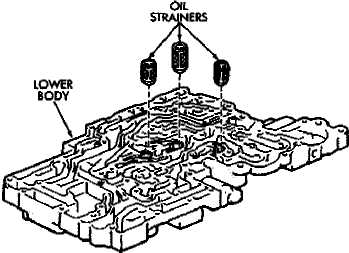
Fig. 2 Removing/Installing Lower Body Oil Strainers
WARNING: THE PRIMARY REGULATOR VALVE SLEEVE AND PLUNGER ARE UNDER TENSION FROM THE VALVE SPRING. EXERT COUNTERPRESSURE ON THE SPRING WHILE REMOVING THE VALVE RETAINER TO PREVENT COMPONENTS FROM FLYING OUT.

Fig. 3 Valve Retainer And Clip Location
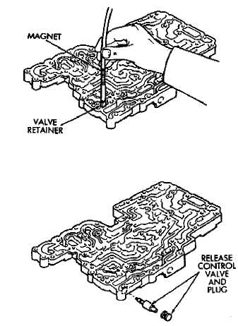
Fig. 4 Removing/Installing Release Control Valve
(a) Note position of valve retainer for assembly reference (Fig. 6). Then press valve sleeve inward with your thumb and remove retainer with magnet.
(b) Slowly release thumb pressure on sleeve and remove sleeve, spring and washer and valve (Fig. 7). Use magnet to remove valve if necessary.
(8) Remove regulator valve plunger from sleeve (Fig.8).
(9) Remove retaining clip and remove pressure re ducing plug (Fig. 9). Cover screwdriver blade with tape
to avoid scratching valve body surface.
(10) Remove accumulator control valve retainer and remove control valve assembly (Fig. 10).
(11) Remove spring and control valve from valve sleeve (Fig. 11).
(12) Clean lower body valve components with solvent and dry them with compressed air only. Do not use shop towels or rags. Lint or foreign material from towels or rags can interfere with valve operation.
(13) Inspect condition of lower body components. Replace lower body if any bores are scored or corroded. Replace valves, plugs or sleeves that are scored or worn. Replace oil strainers if cut, torn or damaged in any way.
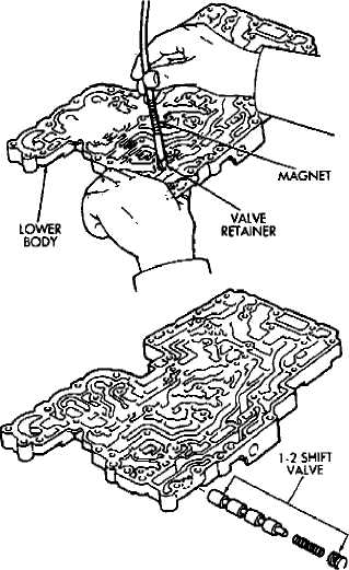
Fig. 5 Removing/Installing 1-2 Shift Valve
(14) Inspect the valve body springs. Replace any spring having rusted, distorted, or collapsed coils. Measure the length of each valve body spring. Replace any spring if free length is less than the length specified in the following chart (Fig. 12).
Lower Body Assembly
Lubricate lower body components with automatic
transmission fluid.
Install spring and accumulator control valve in
sleeve (Fig. 11). Then install assembled components in
lower body (Fig. 10K
(31 Press accumulator control valve assembly into valve bore and install retainer (Fig. 10).
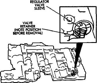
Fig. 6 Regulator Valve Retainer Position
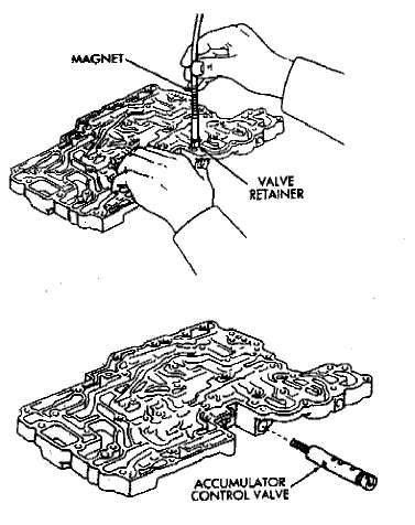
Fig. 10 Removing/Installing Accumulator Control Valve Assembly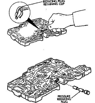
Fig. 9 Removing/Installing Pressure Reducing Plug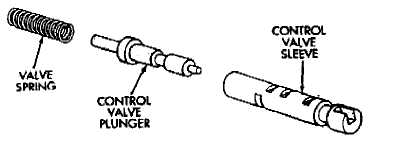
secure plug with retaining clip (Fig. 9),
(Fig. 13).
Install primary regulator valve plunger in valve
sleeve (Fig. 8).
Install valve spring and regulator valve sleeve and
plunger.
(8) Press regulator valve sleeve into bore and install
retainer (Fig. 6 and 7). Be sure retainer is positioned in
sleeve lugs as shown.
VALVE
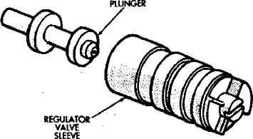
Fig. 8 Removing/Installing Regulator Valve Plunger
(ß) Install 1-2 shift valve, spring and plug (Fig. 5). Then press valve assembly into bore and install retainer:
110) Install release control valve and plug in bore and install valve retainer (Fig, 4).
(ID Install replacement O-rings on solenoids and install solenoids on valve body. Tighten solenoid attaching bolts to 10 ąm (7 ft-lbs) torque.
Install oil strainers (Fig. 14). Identify strainers
before installation. The three strainers are all the
same diameter but are different lengths. Two
strainers are 11.0 mm (.443 in) long while one
strainer is 19.5 mm (.76 in) long (Fig. 14).
Install check valves and springs/seats (Fig. 1)
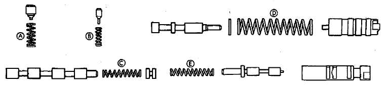
Spring | Free Length |
(A) Check Valve | 20 2 mm (0.801 In.) |
(B) Pressure Relief Voke | 11.2 mm 10.441 in.) |
|Q 1-2 Shift Valve | 30.8 mm (1.213 in.) |
(Dl Primary Regulator Valve. | 66.7 mm (2.626 in.) |
(E) Accumulator Control Valve | 36,1 mm (1.421 in.) |
Fig. 12 Lower Body Valve Spring Dimensions
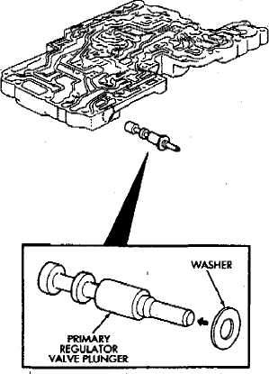
Fig. 13 Installing Washer On Regulator Valve Plunger
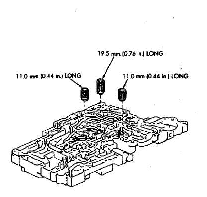
Fig. 14 Oil Strainer Identification
Upper Body Disassembly and Inspection
(1) Remove valve body plate and gaskets (Fig. 1).
Discard gaskets.
Remove strainer and nine check balls (Fig. 2). Note
check ball and strainer position for assembly reference
Remove valve stop and throttle cam (Fig. 3).

Fig. 3 Removing/Installing Valve Stop And Throttle Cam
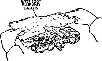
Fig. 1 Removing/Installing Upper Body Plate And Gaskets
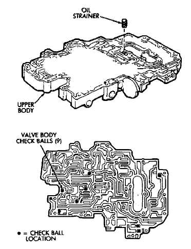
Fig. 2 Cheek Ball And Strainer Location
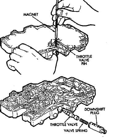
Fig. 4 Removing/Installing Throttle Valve
(5) Turn upper body over and remove throttle valve adjusting iings and spring (Fig. 5). Note number of adjusting rings if valve is equipped with them.
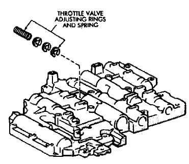
Fig. 5 Throttle Valve Adjusting Ring Location (If Equipped)
Remove 3-4 shift valve retainer with magnet and
remove valve plug, spring and 3-4 shift valve (Fig. 6).
Remove second coast modulator valve retainer and
remove valve plug, spring and valve.
Remove lock-up relay valve retainer and remove
relay valve and sleeve assembly (Fig. 8).
Remove lock-up relay valve, spring and plunger
fromtalve sleeve (Fig. 9).
Remove secondary pressure regulator valve re
tainer and remove plug, regulator valve and spring
(Fig. 10).
Remove cut-back valve retainer and remove plug,
cut-back valve and spring (Fig. 11).
Remove 2-3 shift valve retainer and remove plug,
spring and 2-3 shift valve (Fig. 12).
Remove low coast modulator valve retainer and
remove valve plug, spring and low coast modulator
valve (Fig. 13).
Clean the upper body components with solvent
and dry them with compressed air only. Do not use shop
towels or rags. Lint or foreign material from towels or
rags can interfere with valve operation.
Inspect condition of the upper body components.
Replace the upper body if any of the bores are scored or
corroded. Replace any valves, plugs or sleeves if scored
or worn. Replace the oil strainer if cut, torn or damaged
in any way-

Fig. 6 Removing/Installing 3-4 Shift Valve
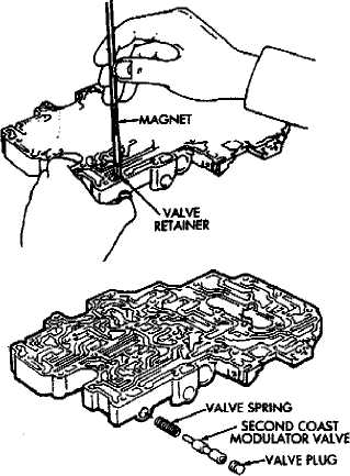
Fig. 7 Removing/Installing Second Coast Modulator Valve
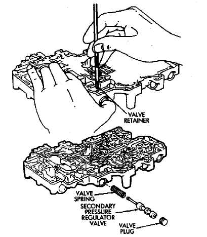
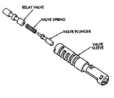
Fig. 9 Lockup Relay Valve Components
(16) Inspect the valve body springs. Replace any spring having rusted, distorted, or collapsed coils. Measure length of each spring. Replace any spring if fuse length is less than specified in the chart (Fig. 14).
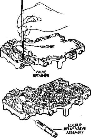
Fig. 8 Removing/Installing Lockup Belay Valve
Upper Body Assembly
Lubricate the valves, springs, plugs, sleeves and
the valve bores in the upper body with automatic trans
mission fluid.
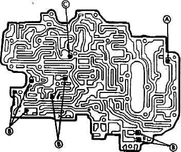
Note position of the valve retainers (A) and stop (B)
for assembly reference (Fig. 15).
Install low coast modulator valve, spring and plug
in valve bore. Press valve plug inward and install re
tainer (Fig. 13).
Install 2-3 shift valve, spring and plug in valve
bore. Press plug inward and install retainer (Fig. 12).
Install cut-back valve spring, valve and plug (Fig.
11). Press plug inward and install retainer.
Install secondary regulator valve spring, valve
and plug in valve bore. Press plug inward and install
retainer (Fig. 10).
Assemble lock-up relay valve. Install spring and
plunger in valve sleeve (Fig. 9). Then install assembled
valve in sleeve.
Install assembled lock-up relay valve in valve bore
and install retainer (Fig. 81.
Install second coast modulator valve, spring and
plug in valve bore. Press plug inward and install re
tainer (Fig. 7).
(10) Install 3-4 shift valve, spring and plug in bore.
Press plug inward and install retainer (Fig. 6).
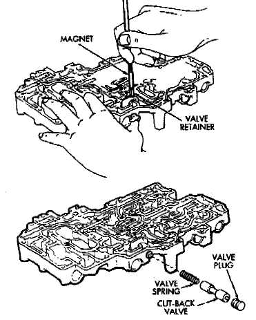

Fig. 10 Removing/Installing Secondary Pressure Regulator Valve

Fig. 11 Removing/Installing Cut-Back Valve
Fig. 12 Removing/Installing 2-3 Shift Valve
Install throttle valve in valve bore. Push valve
into place and install valve stop (Fig. 16).
On models with adjusting rings, turn upper body
over and install adjusting rings (Fig. 17). Be sure to
install same number of rings as were removed.
Install throttle valve adjusting spring in bore and
onto end of throttle valve (Fig. 18).
Fig. 13 Removing/Installing Low Coast Modulator Valve
Install downshift spring and plug in throttle
valve bore. Press plug inward against throttle valve and
spring and install the retainer pin (Fig. 19).
Install sleeve in throttle cam (Fig. 20).
Install spring on cam (Fig. 20). Hook curved end
of spring through hole in cam as shown.
Mount cam on upper body and install cam at
taching bolt and spacer (Fig. 20). Tighten bolt to 10 N-m
(7 ft-Ibs) torque.
Be sure straight end of spring is seated in upper
body slot as shown (Fig. 20).
Install check balls in upper body (Fig. 21). Refer
to illustration for check ball identification and location.
Install oil strainer (Fig, 2).
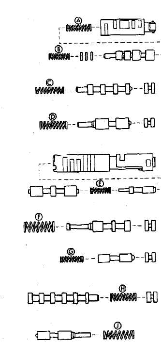
Spring | Flee Length |
(A) Downshift Plug | 27.3 mm (1.074 in.) |
(B) Throttle Valve | 20.6 ęě (0.811 irv.| |
(C| 3-4 Shift Valve | 30.8 mm 11.212 inj |
|D) Second Coast Modulator Valve | 25.3 nun (0.996 in.) |
(E) Lockup May Valve | 21.4 mm (0.843 in.) |
(F) Second Regulator Vain | 30.9 mm (1.217 in.| |
|G) Cut-Bock Valve | 51.8 mm |0 858 in.) |
(H) 2-3 Shift Valve | 30.8 mm (1.212 in.) |
(J) Low Goast Modulator Valve | 27.8 mm (1.094 in.) |
Fig. 14 Upper Body Spring/Valve Identification


Fig. 17 Install Throttle Valve Adjusting Rings - If Equipped
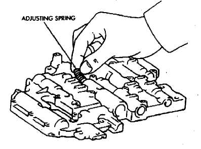
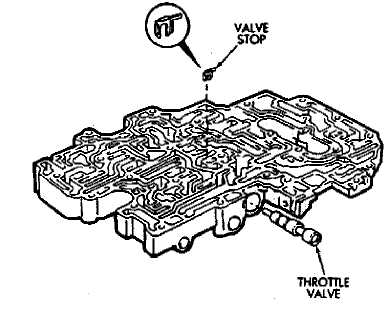
Fig. 15 Valve Retainer And Stop Locations
Fig. 18 Installing Throttle Valve Adjusting Spring
Fig. 16 Installing Throttle Valve And Stop
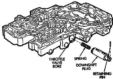
Fig. 19 Installing Downshift Plug
SIHVE
CheckBoll Diameter ® Rubber Ball 6.35 mm (0.2500 in.) ® Steel Ball 556 mm (0.2189 in,) © Steel Ball 7.14 mm (0.2811 in.) |
Fig. 21 Upper Body Cheek Ball Location/Identification
Installing Upper Body On Lower Body
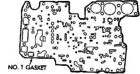
Fig. 1 Valve Body Gasket No. 1
Position new No. 1 gasket (Fig. 1) on upper body.
Position valve body plate on No. 1 gasket.
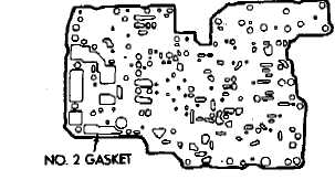
Position new No. 2 gasket (Pig. 2) on valve body
plate and align gaskets and plate using bolt holes as
guides,
Install valve body bolts. Three different length
bolts are used. Refer to the Figure 3 for bolt loca
tions. Chart symbols indicate bolt location and
length in millimeters.
Tighten valve body bolts to $.4 N-m (56 in-lbs)
torque.
Fig. 20 Installing Throttle Cam
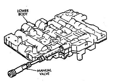
Install manual valve (Fig- 4).
Install two-piece detent spring (Fig. 5). Tighten
spring attaching bolt to 10 *m (7 ft-lbs) torque.
Fig. 4 Installing Manual Valve
Fig. 2 Valve Body Gasket No. 2
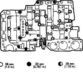
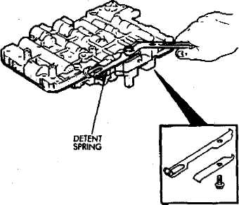
Fig. 3 Valves Body Bolt Location/Size
Fig. 5 Installing Detent Spring
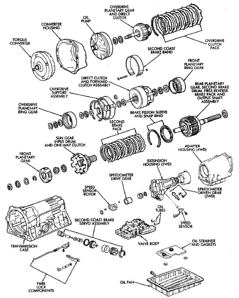
Fig. 1 AW-4 Transmission Components
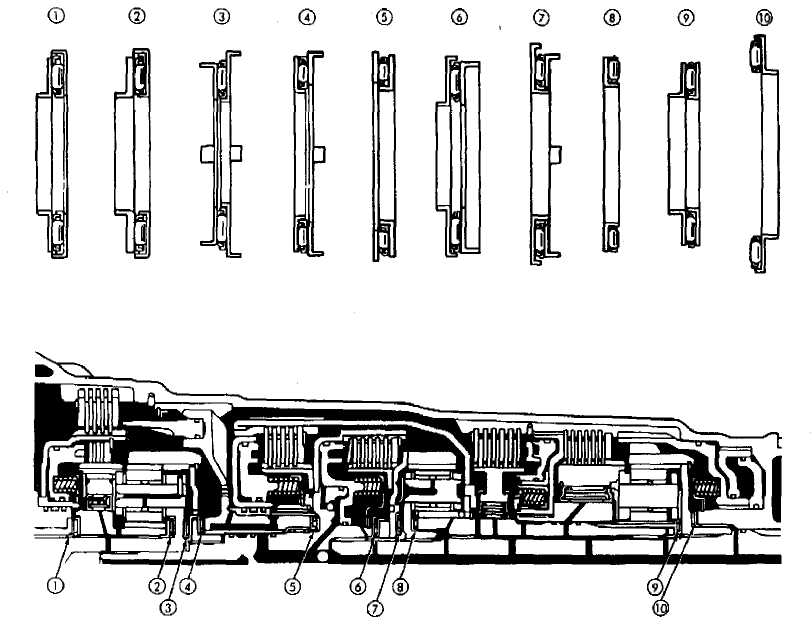
Fig. 2 Thrust Bearing Chart
TRANSMISSION ASSEMBLY
(1) During assembly, lubricate components with
transmission fluid or petroleum jelly as indicated.
If any of the transmission components are still
assembled after overhaul checking procedures, disas
semble as necessary in preparation for transmission
assembly.
Verify thrust bearing and race installation during
assembly. Refer to the Thrust Bearing Chart (Fig. 2) for
bearing and race location and correct positioning.
14) Install rear planetary gear, second brake drum and output shaft as outlined in following steps:
(5) Verify No. 10 thrust bearing and race (Fig. 2). Bearing and race outer diameter is 57.7 mm (2.272 in); inside diameter is 39.2 mm (1.543 in).
16) Coat thrust bearing and race assembly with petroleum jelly and install in case (Fig. 3). Race faces down. Bearing rollers face up.
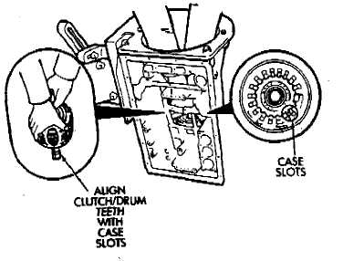
Align teeth of second brake drum and clutch pack
(Fig. 4).
Align rear planetary-output shaft ŕâýĺňŰó teeth
with case slots and install assembly in case (Fig. 5).
Install rear planetary snap ring with snap ring
pliers B.Vi. FM- 29. Chamfered side of snap ring faces
up and toward caae front (Fig. 6).
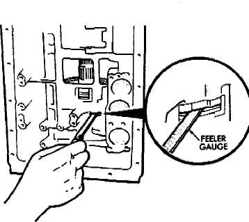
Check first-reverse brake pack clearance with
feeler gauge-Clearance should be: 0.6 to 1.74 mm (.024
to .069 in) on 4-cyl. transmissions and .70 to 2.00 mm
(.028 to .079 in) on 6-cyl. transmissions. If clearance is
incorrect, planetary assembly, thrust bearing or snap
ring is not properly seated in case. Remove and reinstall
components if necessary -
Install second brake piston sleeve (Pig. 8). Sleeve
lip faces up and toward case front as shown.
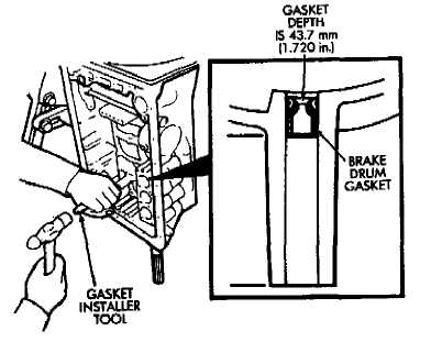
Install second brake drum gasket with tool B.Vi.
FM-33 (Fig. 9>. Gasket depth is 43.7 mm (1.720 in).
(13) Install park lock pawl, spring and pin (Fig. 10).
(14) Connect park lock rod to manual valve shift sector (Fig. 11).
(15) Position park lock rod bracket on case and tighten bracket attaching bolts to 10 ąm (7 ft-lbs) torque (Fig, 12).
(16) Verify park lock operation. Move shift sector to
Park position. Park pawl should be firmly engaged
(locked) in planetary ring gear (Fig. 13).
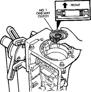
(17) Install No. 1 one-way clutch (Fig. 14). Short
flanged side of cluteh faces up and toward case front.
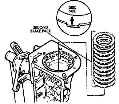
Install second brake pack (Fig. 15). Install disc
then plate. Continue installation sequence until correct
number of discs-plates are installed. Use five discs
and five plates in 6-cyl. transmissions and four
discs and four plates in 4-cyl. transmissions.
Install second brake pack retainer with rounded
edge of retainer facing disc.
Install second brake pack snap ring.
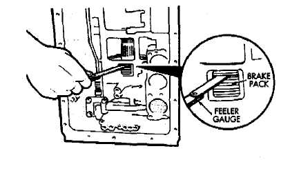
Check brake pack clearance with feeler gauge
(Fig. 16). Clearance should be: 89 to 2.15 mm (.035 to
.084 in) on 4-cyl. transmissions and .062 to 1.98 mm
(.024 to .078 in> on 6-cyl. transmissions If brake pack
clearance is not correct, brake pack components are not
seated. Reassemble brake pack if necessary.
Fig. 3 Installing Thrust Bearing And Race (No. 10)
Fig. S Installing Output Shaft/Rear Planetary Assembly
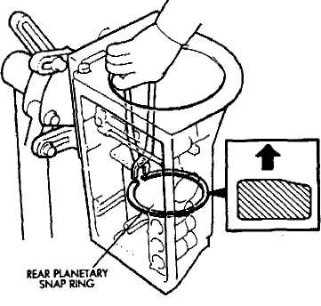
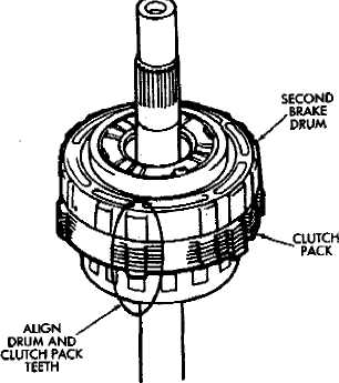
Fig. 4 Align Drum And Clutch Pack Teeth
Fig. 6 Installing Planetary Snap Ring
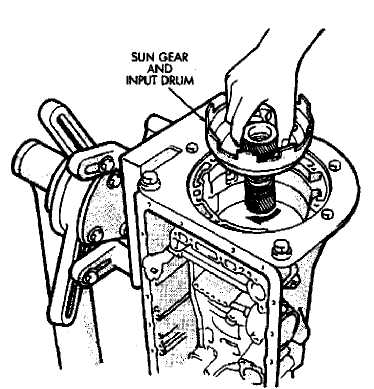
Install planetary sun gear and input drum (Pig.
17). Be sure drum thrust washer tabs are seated in
drum. Use petroleum jelly to hold thrust washer in
position if necessary.
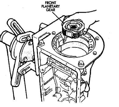
Install front planetary gear on sun gear (Fig. 18).
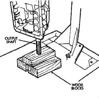
Support output shaft with wood blocks (Fig. 19).
Install planetary snap ring on sun gear with tool
B.Vi. FM-30.
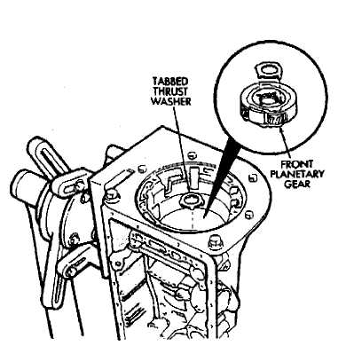
Install tabbed thrust race on front planetary gear
(Fig. 21). Washer tabs face down and toward gear. Race
outer diameter is 47.8 mm (1.882 in); inside diameter is
34.3 mm (1,350 in).
Install second coast brake band (Fig. 22).
(28) Install pin in second coast brake band. Then install retaining ring on pin (Fig. 23).
Install thrust bearing and race in forward-direct
clutch (Fig. 24). Coat bearing/race with petroleum jelly
to hold them in place-
Verify forward-direct clutch thrust bearing size.
Race outer diameter is 48-9 mm (1.925 in); inside di
ameter is 26.0 mm (1.024 in). Bearing outer diameter is
46.7 mm (1.839 in); inside diameter is 26.0 mm (1.024
in).
Coat front planetary ring gear race with petro
leum jelly and install it in ring gear (Fig. 25).
Fig. 5 Installing Second Brake Drum Gasket

Fig. 7 Checking First-Reverse Brake Pack Clearance
PISTON I SLEEVE
Fig. 8 Installing Second Brake piston Sleeve
Fig. 10 Installing Park Lock Pin/Spring/Pawl
(32) Verify ring gear race size. Outer diameter is 47.0 mm (1.850 in); inside diameter is 26.5 mm (1.045 in).
(33) Align forward-direct clutch disc splines with screwdriver (Fig. 26).
(34) Align and install front planetary ring gear in forward-direct clutch (Fig. 27).
(35) Coat bearing and race with petroleum jelly and install them in ring gear (Fig. 28). Verify bearing/race size. Bearing outer diameter is 47.7 mm (1.878 in); inside diameter is 32.6 mm (1.283 in). Race outer diameter is 53.6 mm (2.110 in); inside diameter is 30.6 mm (1.205 in).
(36) Rotate front of transmission case downward and install assembled planetary gear/forward-direct clutch (Fig. 29).
(37) Check clearance between sun gear input drum and direct dutch drum (Fig. 30). Clearance should be 9.8 to 11.8 mm (.386 to .465 in). If clearance is incorrect,
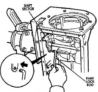
Fig. 11 Installing Pork Lock Rod
PARK ROD BRACKET
 Ř
Ř
planetary gear/forward-direct clutch assembly is not seated or is improperly assembled. Remove, and correct if necessary.
Coat thrust bearing and race assembly with pe
troleum jelly and install it on clutch shaft. Bearing faces
up and toward case front as shown (Fig. 31). Verify
bearing/race size. Bearing and race outer diameter is
47.8 mm (1.882 in); inside diameter is 33.6 mm (1.301
in).
Assemble second coast brake piston components
(Fig. 32).
(40) Install assembled second coast brake piston in
Fig. 13 Checking Park Pawl Engagement
case.
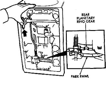
Fig. 12 Installing Park nod Bracket
Fig. 14 Installing No. 1 One-Way Clutch
Install replacement seals on second coast brake
piston cover and install cover in case.
Install second coast brake piston snap ring with
tool B.Vi. FM-29 (Fig. 33).
Check second coast brake piston stroke as follows:
Fig. 15 Installing Second Brake Pack
Fig. 16 Checking Second Brake Pack Clearance
Make reference mark on brake piston rod (Fig.
34).
Apply 57-114 psi air pressure through feed
hole (Fig. 34). Alternately apply and release air pres
sure to operate piston,
Check stroke with gauge (Fig. 35). Use gauge
B.Vi.FM. 40 with 4-cyl. transmission. Use gauge B.-
Vi.FM. 41 with 6-cyl. transmission. .
If stroke length is incorrect, piston, cover or
snap ring is not seated. Reassemble and check stroke
again if necessary.
Fig, 17 Installing Sun Gear And Input Drum
Fig. 18 Installing Front Planetary Gear
Coat thrust race and tabbed washer with petro
leum jelly and install them on overdrive support (Fig.
36). Verify race siie. Race outer diameter is 50.9 mm
(2.004 in); inside diameter is 36.2 mm (1.426 in).
Install overdrive support in case. Use two long
bolts to help align and guide support into position (Fig.
37).
Install overdrive support snap ring with tool
B.Vi. FM-29 (Fig. 38). Chamfered side of snap ring faces
up and toward case front. Snap ring ends must be
aligned with case opening with ring ends approximately 24 mm (0.94 in) from centerline of case opening.
Install and tighten overdrive support bolts to 25
ąro (19 ft-lbs) torque (Fig. 39).
Check output shaft end play with dial indicator
(Fig. 40). End play should be .27 to 0.86 mm (.0106 to
.0339 in).
If output shaft end play is incorrect, one or more
of installed components is not seated. Reassemble as
necessary and check end play again.
(501 Install overdrive clutch pack (Fig. 41)_Install thickest clutch plate first. Rounded edge of plate faces
up. Install first disc followed by another plate until correct number of discs-plates are installed. Install four discs and three plates in a 6-cyl. transmission and three discs and two plates in a 4-cyl. transmission.
(51) Install stepped ring retainer plate with flat side
facing disc. Then install brake pack snap ring (Fig. 42).
(52) Check overdrive brake piston stroke aa follows:
(a) Mount tool B.Vi. FM-35 in dial indicator and
position gauge tool B.Vi. FM. 35 against overdrive brake piston (Fig. 43).
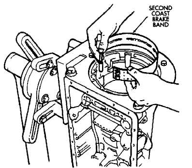
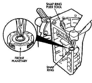
Fig. 19 Supporting Output Shaft
Fig. 21 Installing Planetary Thrust Race
Fig. 22 Installing Second Coast Brake Band