1993 Jeep Cherokee
1993 CHRYSLER CORP. ENGINES 2.5L 4-Cylinder
Jeep: Cherokee, Wrangler
ENGINE IDENTIFICATION
NOTE: For engine repair procedures not covered in this article,
see ENGINE OVERHAUL PROCEDURES - GENERAL INFORMATION article in the GENERAL INFORMATION section.
Engine can be identified by eighth character of Vehicle Identification Number (VIN). The VIN is stamped on a plate attached to top left corner of instrument panel.
Engine code is on a machined surface on right side of cylinder block between cylinders No. 3 and 4. This code may be required when ordering replacement parts.
ENGINE IDENTIFICATION CODES TABLE
Application VIN Code
2 . 5L 4-Cylinder PFI P
Some engines are manufactured with oversize or undersize components. These engines are identified by a letter code stamped on oil filter boss near distributor. Letters are decoded as follows:
"B" indicates all cylinder bores .010" (.25 mm) oversize.
"C" indicates all camshaft bearing bores .010" (.25 mm)
oversize.
* "M" indicates all main bearing journals .010" (.25 mm)
undersize.
* "P" indicates one or more connecting rod journals .010" (.25
mm) undersize.
* "PM" indicates all crankshaft main bearing journals and one
or more connecting rod journals .010" (.25 mm) undersize.
ADJUSTMENTS
VALVE CLEARANCE ADJUSTMENT
Engine is equipped with hydraulic valve lifters. No valve adjustment is required.
REMOVAL & INSTALLATION
NOTE: For reassembly reference, label all electrical connectors, vacuum hoses and fuel lines before removal. Also place mating marks on engine hood and other major assemblies before removal.
CAUTION: When battery is disconnected, vehicle computer and memory systems may lose memory data. Driveability problems may exist until computer systems have completed a relearn cycle. See COMPUTER RELEARN PROCEDURES article in GENERAL INFORMATION before disconnecting battery.
FUEL PRESSURE RELEASE
CAUTION: Fuel system is under constant pressure. This pressure must be released before disconnecting or servicing any fuel supply or return system component. Wear proper eye protection when releasing fuel system pressure.
Disconnect negative battery cable. Remove fuel filler cap. Remove cap from pressure test port on fuel rail. See Fig. 1. Place shop towels around pressure test port to absorb spilled fuel. Press test port valve with a small screwdriver or punch wrapped in shop towels. Remove shop towels and dispose of properly. Install pressure test port cap.
CAUTION: Always replace "O" rings, spacers and retainers whenever
fuel system quick-connect fittings are disconnected. Ensure fuel connections are secure by verifying that only retainer tabs protrude from connectors, and by pulling on tubes to verify that they are secure.
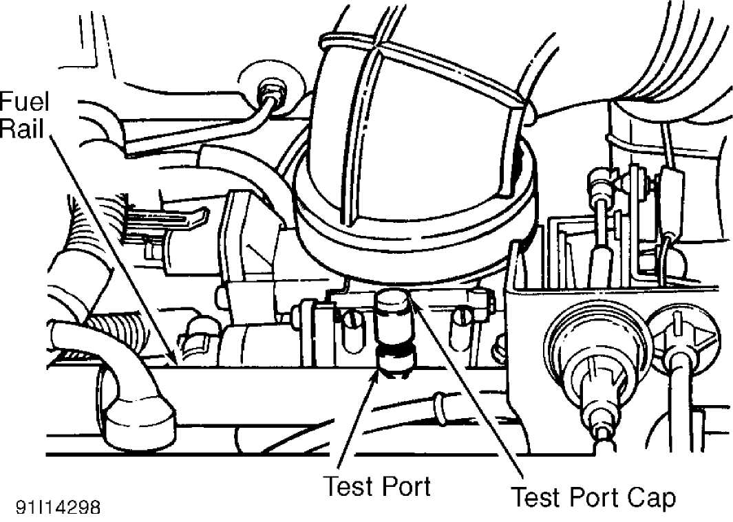
Fig. 1: Locating Fuel Pressure Bleeding Test Port Courtesy of Chrysler Corp.
COOLING SYSTEM BLEEDING
CAUTION: Engine coolant may be hot. To avoid scalding, carefully
release system pressure before removing radiator cap or drain cock.
Fill radiator completely and install pressure cap. Fill reserve/overflow tank to FULL mark. Operate engine until it reaches normal operating temperature. Shut off engine and allow it to cool. Recheck coolant level in reserve/overflow tank as necessary. Add coolant ONLY when engine is cold.
ENGINE
Removal (Cherokee)
Remove
battery and air cleaner. Remove hood. Drain cooling
system.
Remove radiator hoses, coolant recovery hose and fan
shroud.
Disconnect transmission fluid cooler lines (if equipped).
Discharge
A/C system (if equipped). Discharge A/C
system
using approved refrigerant recovery/recycling equipment.
Remove A/C
condenser (if equipped) and
radiator. Remove fan. To maintain pulley
and
water pump alignment, install a 5/16 x
1/2" bolt through fan
pulley
into water pump flange.
Disconnect
heater hoses, throttle linkage, cruise control
cable
(if equipped) and throttle valve rod. Disconnect wires from
starter
solenoid, oxygen (O2) sensor and all fuel
injection harness
connections.
Release fuel pressure. See FUEL PRESSURE RELEASE.
Disconnect fuel supply and return lines at fuel rail. Disconnect TDC sensor wire connector. Remove A/C service valves and cap compressor ports (if equipped).
Remove
vacuum check valve from power brake booster (if
equipped).
Disconnect power steering hoses at steering gear
(if
equipped). Drain
power steering pump reservoir. Cap power steering
hoses
and fittings.
Tag and
disconnect any remaining hoses or electrical
connectors. Raise
and support vehicle. Disconnect exhaust pipe from
exhaust
manifold. Remove starter and flywheel cover.
On
automatic transmission equipped models, mark converter
and
flexplate for installation reference. Remove converter-to-
flexplate
bolts. On all models, remove upper bellhousing bolts and
loosen
bottom bolts. Remove engine mount bolts.
Remove
engine shock damper bracket. Lower vehicle. Attach
lifting
device to engine. Raise engine from front supports. Place
support
under bellhousing. Remove remaining bellhousing bolts.
Remove
engine.
Removal (Wrangler)
Pad
windshield with cloth. Raise hood and rest it against
windshield
frame. Drain cooling system. Remove battery. Disconnect
wiring
from alternator, ignition coil, distributor, oil pressure
sender
and fuel injection wire harness.
Disconnect
fuel line quick-connect couplings at fuel rail.
Remove engine
ground strap. Remove air cleaner. Disconnect vacuum
purge hose
from vapor canister tee. Unplug idle speed actuator
connector.
Disconnect throttle cable and remove it from bracket.
Disconnect
throttle rod at bellcrank. Unplug oxygen (O2)
sensor
connector. Disconnect coolant hoses at radiator, intake
manifold
and thermostat housing. Remove fan shroud and radiator.
Remove
fan and spacer. Install a 5/16 x 1/2"
bolt through fan pulley
into
water pump flange to maintain pulley and water pump alignment.
Remove
check valve from power brake booster (if equipped).
Disconnect
power steering hoses at steering gear (if equipped).
Drain
power steering pump reservoir. Cap power
steering hoses and fittings.
Tag and
disconnect any remaining hoses or electrical
connectors. Raise
and support vehicle. Disconnect exhaust pipe from
exhaust manifold. Remove starter. Remove flywheel housing access cover. Remove engine mount through-bolts. Remove upper bellhousing bolts. Loosen lower bellhousing bolts.
6) Lower vehicle. Attach lifting device to engine. Raise engine from front supports. Place support under bellhousing. Remove remaining bellhousing bolts. Lift engine from engine compartment.
Installation (All Models)
Remove engine mount cushions from brackets to aid alignment of engine and transmission. To complete installation, reverse removal procedure. Adjust throttle and cruise control linkage (if equipped). Tighten bolts to specification. See TORQUE SPECIFICATIONS table. Refill and check fluid levels.
INTAKE MANIFOLD
Removal
Disconnect
negative battery cable. Remove air inlet hose
at throttle body
and air cleaner. Remove power steering pump with
hoses attached
and wire it aside.
Release
fuel pressure. See FUEL PRESSURE RELEASE. Remove
power steering
pump brackets at water pump and intake manifold.
Disconnect fuel
supply and return lines at fuel rail.
Disconnect
accelerator cable. Unplug cruise control
connector at throttle
body, using finger pressure only. Remove
crankcase ventilation
and manifold pressure sensor hoses. Tag and
disconnect all wiring
and hoses.
Remove
bolts No. 2 through 5 securing
intake manifold to
cylinder head. See Fig. 2. Slightly
loosen bolt No. 1 and nuts No. 6
and
7. Remove intake manifold. Drain coolant
from manifold.
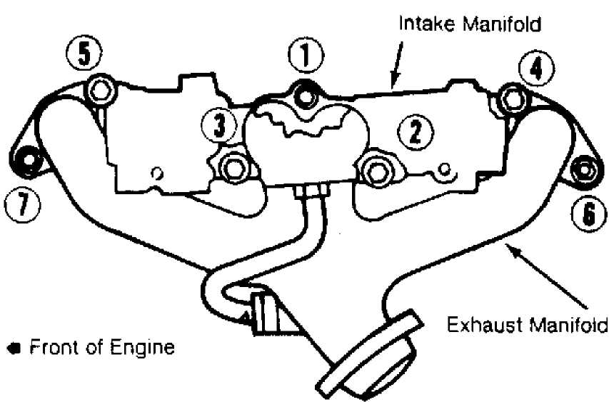
Fig. 2: Intake & Exhaust Manifold Bolt Tightening Sequence Courtesy of Chrysler Corp.
Installation
Ensure all gasket surfaces are clean. Install intake
manifold. Finger tighten all bolts. Tighten intake manifold bolts to specification in correct sequence. See Fig. 2. Also see
TORQUE SPECIFICATIONS table. To complete installation, reverse removal procedure. Fill and bleed cooling system.
EXHAUST MANIFOLD
Removal
Disconnect negative battery cable. Remove intake manifold. See INTAKE MANIFOLD. Raise and support vehicle. Disconnect exhaust pipe from exhaust manifold. Lower vehicle. Remove retaining nuts and bolts. Remove exhaust manifold.
Installation
Clean
all gasket surfaces. Install intake and exhaust
manifolds
together, using NEW gasket. Ensure exhaust manifold is
centrally
located over end studs and spacer. Tighten bolt No. 1
to
specification.
See TORQUE SPECIFICATIONS table. Tighten bolts No. 2
through
5 to specification in sequence. See Fig.
2.
Install
new spacers over cylinder head studs. Tighten nuts
No.
6 and 7 to
specification. To complete installation, reverse
removal
procedure. Start engine and check for leaks.
CYLINDER HEAD
Removal
Disconnect
negative battery cable. Drain cooling system.
Remove accessory
drive belt. Remove A/C compressor (if equipped) and
wire it
aside. DO NOT discharge A/C system. Remove air cleaner.
Remove A/C
compressor mounting bracket-to-cylinder head
bolts. Loosen A/C
compressor mounting bracket-to-cylinder block bolts.
Disconnect
upper radiator hose and heater hoses. Remove valve cover.
Remove
rocker arms, bridges, pivots and push rods. Tag all
parts for
installation reference. See ROCKER ARMS. Remove manifolds.
See
INTAKE MANIFOLD and EXHAUST MANIFOLD.
Tag and
disconnect spark plug wires. Remove spark plugs.
Remove cylinder
head bolts. Remove cylinder head. Stuff clean lint-
free shop
towels into cylinder bores.
Inspection
Inspect
cylinder head for cracks or damage. Using
straightedge, check
cylinder head for warpage across bolt holes and
diagonals.
Resurface or replace cylinder head if warpage exceeds
specification
or damage exists. See CYLINDER HEAD table under
ENGINE
SPECIFICATIONS.
Cylinder
head bolts may be REUSED ONLY ONCE. If this is
the first time
cylinder head has been removed, put a dab of paint on
the head of
each bolt. If the bolts already have paint on them, or if
it is
unknown whether they have been used before, DISCARD THEM and
replace
with NEW bolts.
Installation
Clean
carbon from combustion chambers and tops of pistons.
Ensure all
gasket surfaces, head bolts and head bolt holes are clean.
Install
NEW cylinder head gasket with numbers or word TOP upward. DO
NOT
apply sealant to cylinder head gasket. Ensure all holes
align
properly.
Install
cylinder head. Apply sealing compound to threads
of
cylinder head bolt No. 7 before
installation. Install cylinder head
bolts. Tighten all bolts in 3
stages in sequence to specs. See Fig. 3.
For
torque specifications see TORQUE SPECIFICATIONS table.
NOTE: During the final tightening sequence, bolt No. 7 will be
tightened to a lower torque than the others.
3) To complete installation, reverse removal procedure. Install all valve train components into their original locations. Refill cooling system. Remove coolant temperature sensor to bleed air from system while filling.
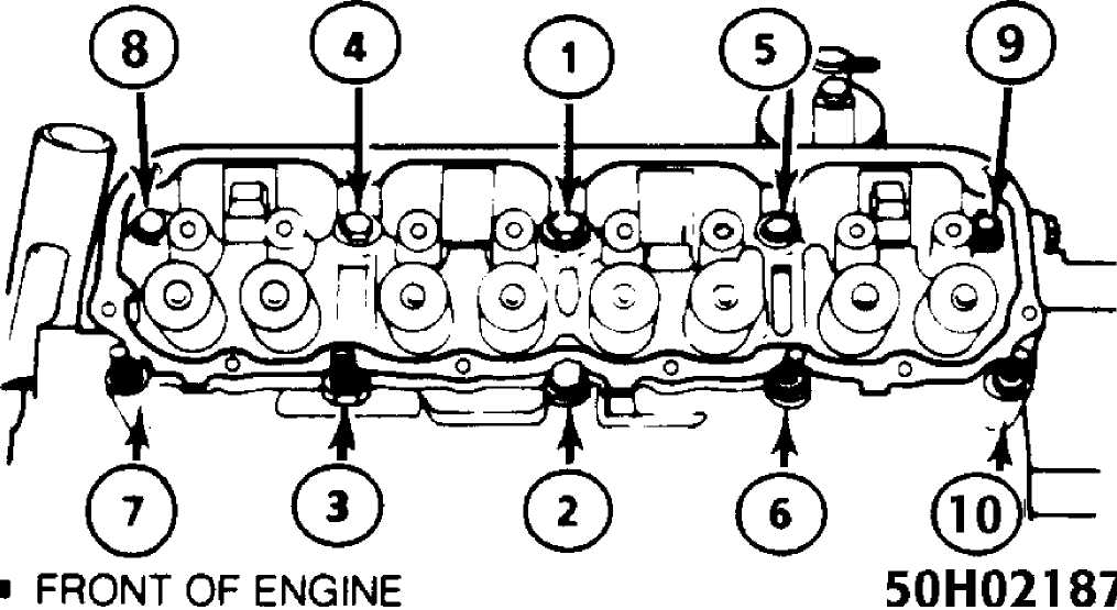
Fig. 3: Cylinder Head Bolt Tightening Sequence Courtesy of Chrysler Corp.
FRONT COVER OIL SEAL
Removal & Installation
1) Remove drive belt. Remove vibration damper. Remove
radiator shroud. Remove seal from front cover. Apply sealant to outer diameter of new seal. Coat crankshaft lightly with oil.
2) Drive
seal into front cover, using Front Cover
Aligner/Seal
Installer (6139). Lightly coat seal contact
area of
vibration damper with oil.
Lubricate vibration damper bolt with oil
before
installation. Reverse removal procedure to complete
installation.
See TORQUE SPECIFICATIONS table.
TIMING CHAIN & SPROCKETS
Removal
Disconnect
negative battery cable. Remove drive belt, fan
and hub assembly.
Remove fan shroud. Remove accessory drive brackets
attached to
timing case cover. Remove A/C compressor (if equipped)
with hoses
attached and wire it aside. DO NOT discharge A/C system.
Remove
alternator bracket assembly from cylinder head.
Remove
vibration damper retaining bolt and washer. Remove
vibration
damper and key. Remove front cover retaining bolts and front
cover.
Cut oil pan gasket flush with face of cylinder block. Remove
cut-off
pieces.
Rotate
crankshaft until timing marks on crankshaft and
camshaft
sprockets align. See Fig. 4. Remove oil
slinger and camshaft
sprocket retaining bolt. Remove sprockets and chain as an assembly. Remove front cover oil seal.
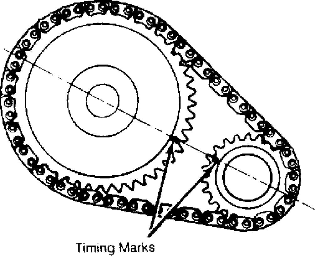
Fig. 4: Aligning Sprocket Timing Marks Courtesy of Chrysler Corp.
Installation
1) Turn tensioner lever down to unlock position. Pull
tensioner block toward lever to compress spring. Turn lever up to lock position. See Fig. 5. Install timing chain and sprockets as an assembly. Ensure timing marks align. Install camshaft sprocket retaining bolt and washer. Tighten to specification. See the TORQUE SPECIFICATIONS table.
NOTE: Ensure chain tensioner is in unlock (down) position before installing front cover.
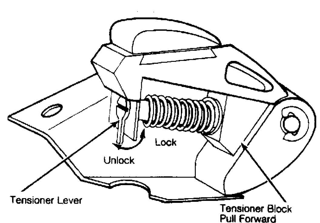
Fig. 5: Locating Chain Tensioner Lock Courtesy of Chrysler Corp.
Verify
proper installation by rotating crankshaft until
timing mark on
camshaft is at approximately one o’clock position.
Timing
sprockets are installed correctly if there are 20 timing
chain
pins between timing marks on both
sprockets.
Clean all
gasket surfaces. Install oil slinger. Apply
sealing compound to
both sides of front cover gasket. Install gasket
onto cylinder
block. Replace front section of oil pan seal with
similar piece
cut from new seal.
Coat
outer surface of NEW seal with RTV sealant and place
into
position. Apply sealant where oil pan and cylinder block meet.
Place
front cover onto cylinder block. Place Front Cover
Aligner/Seal
Installer (6139) in front
engine cover seal area.
Install cover retaining bolts, and tighten to
specification. To complete installation, reverse removal procedure. Lubricate vibration damper retaining bolt before installation, and tighten to specification. See TORQUE SPECIFICATIONS table.
ROCKER ARMS
Removal
Remove valve cover. Alternately loosen rocker arm cap screws one turn at a time to prevent damaging bridges. Remove bridges, pivots, rocker arms and push rods. Tag all parts for reassembly reference.
Installation
1) Lubricate
push rod ends with Mopar Engine Oil Supplement
(4318002).
Install push rods into their original locations.
Ensure
bottom end of each push rod is centered in valve lifter.
Lubricate
pivot contact area of each rocker arm with
engine oil supplement.
Install rocker arms, pivots and bridges into
their original
locations. Loosely install cap screws, then tighten
alternately
one turn at a time to specification. Reverse removal
procedure to
complete installation.
Pour
remaining engine oil supplement over entire valve
train.
Supplement must remain in engine oil for at least 1000 miles
(1600 km), but need not be drained until next scheduled oil change.
CAMSHAFT
Removal
Disconnect
negative battery cable. Drain cooling system.
Discharge
A/C system (if equipped) , using approved
refrigerant
recovery/recycling
equipment. Remove A/C condenser (if equipped) and
radiator. Mark
distributor and engine block for installation
reference.
Remove distributor and ignition wiring. Remove rocker arms,
bridges,
pivots and push rods. See ROCKER ARMS.
Remove valve lifters using Hydraulic Valve Lifter
Remover/Installer (C-4129-A). Tag each valve lifter for installation reference. Remove timing chain and sprockets. See TIMING CHAIN & SPROCKETS. Remove camshaft.
Inspection
Inspect lobes, journals, bearings and distributor drive gear for wear. If camshaft sprocket or chain rubs against engine front cover, examine oil pressure relief holes in rear camshaft journal. Oil pressure relief holes MUST be free of debris.
Installation
Lubricate
camshaft and dip valve lifters into Mopar Engine
Oil
Supplement (4318002). Install camshaft.
Reverse removal procedure
to complete
installation.
Pour
remaining oil supplement over entire valve train.
Supplement must
remain in engine oil for at least 1000 miles
(1600
km), but need not be drained
until next scheduled oil change. Refill
cooling
system. Adjust ignition timing. Check for leaks.
REAR CRANKSHAFT OIL SEAL
Removal
Remove transmission, clutch housing and flywheel or flexplate. Pry oil seal from housing. Avoid damage to surrounding area.
Installation
Coat outer lip of replacement seal with engine oil. Using Installer (6271), install seal flush with cylinder block. Use only NEW bolts when installing flywheel or flexplate. Ensure felt lip is inside flywheel mounting surface to avoid tearing seal. To complete installation, reverse removal procedure. Tighten flywheel or flexplate bolts to specification, then an additional 60 degrees. See the TORQUE SPECIFICATIONS table.
WATER PUMP
Removal
Disconnect negative battery cable. Drain cooling system. Remove fan shroud and drive belts. Remove fan assembly. Disconnect
heater hoses and lower radiator hose at water pump. Remove water pump retaining bolts. Remove water pump.
Installation
Install water pump. Tighten bolts to specification. See TORQUE SPECIFICATIONS table. Ensure pump turns freely. Ensure belt is installed correctly to prevent engine overheating because water pump rotates in wrong direction. To complete installation, reverse removal procedure. Fill and purge air from cooling system. Remove coolant temperature sensor to bleed air from system while filling.
OIL PAN
Removal
Disconnect
negative battery cable. Raise and support
vehicle at side sills.
Drain engine oil. Disconnect exhaust pipe at
exhaust manifold.
Disconnect exhaust hanger at catalytic converter.
Lower exhaust
pipe. Remove starter. Remove flywheel access cover.
Position
jackstand directly under vibration damper. Place
wooden block
between vibration damper and jackstand. Remove through
bolts from
engine mounts. Raise engine enough to remove oil pan.
Remove oil
pan retaining bolts. Remove oil pan by sliding it to rear.
Installation
1) Ensure all gasket surfaces are clean. Fabricate 4
alignment dowels from 1 1/2 x 1/4" bolts. Cut heads off bolts and cut slot in end of bolts to allow removal with screwdriver. Install 2 dowels in timing cover and 2 dowels in block. Slide gasket over dowels into position against block and timing cover.
2) Install
oil pan. Install sufficient bolts to hold oil pan
in
place. Remove alignment dowels. Install remaining oil pan bolts
and
tighten to specification. See TORQUE
SPECIFICATIONS table. To complete
installation,
reverse removal procedure. Fill crankcase. Start engine.
Check
for leaks.
OVERHAUL
CYLINDER HEAD
Inspection
Inspect for cracks in combustion chambers, coolant passages, ports and exhaust valve seats. Using straightedge, check cylinder head for warpage in several areas. Repair or replace cylinder head if warpage exceeds specification or damage exists. See CYLINDER HEAD table under ENGINE SPECIFICATIONS.
Valve Springs
Use Valve Spring Tester (J-22738-02) to test each valve spring. Measure free length of each valve spring. Replace valve springs that do not meet specifications. See VALVES & VALVE SPRINGS table under ENGINE SPECIFICATIONS.
Valve Stem Oil Seals
Replace valve stem oil seals if they have deteriorated or whenever valves are serviced. Oil seals are marked INT and EXH for intake and exhaust valves, respectively. Oversize oil seals must be used with valves having .015" (.38 mm) oversize stems.
Valve Guides
Measure diameter of valve guide approximately 3/8" (10 mm) from valve spring side of head, both parallel and at right angle to long axis of head. If difference between measurements exceeds .0025"
(.063 mm), or if diameter exceeds specification by .003" (.08 mm), ream valve guide for oversize valve stem. See CYLINDER HEAD table under ENGINE SPECIFICATIONS. Reface valve seats after reaming valve guides.
Valve Seats
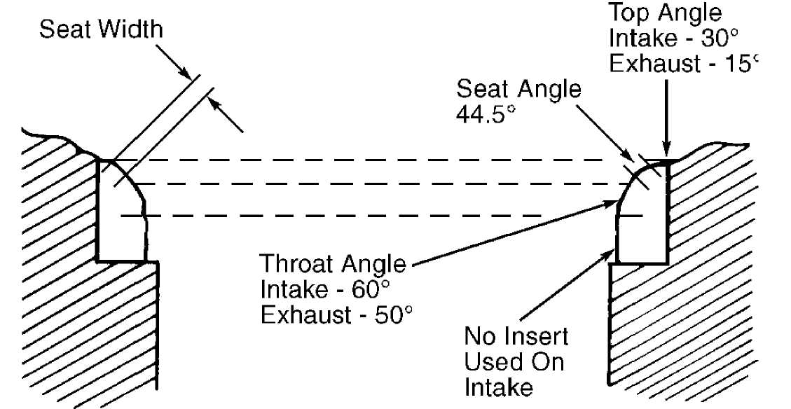
Reface valve seats to specification. Remove only enough metal to provide smooth finish. Use tapered stones to obtain specified seat width. See Fig. 6. Seat width runout should not exceed .0025" (.063 mm) after refacing. See CYLINDER HEAD table under ENGINE SPECIFICATIONS.
Valves
Reface valves to specification. At least 1/32" (.79 mm) margin must remain after refacing valve. Valve stem tip can be resurfaced and chamfered when worn. DO NOT remove more than .01" (.25 mm). See VALVES & VALVE SPRINGS table under ENGINE SPECIFICATIONS.
91C143.00
Fig. 6: Checking Valve Seat Dimensions Courtesy of Chrysler Corp.
VALVE TRAIN
Rocker Arms
Inspect pivot and valve stem contact surfaces of each rocker arm. Replace any rocker arm that is scuffed, pitted, cracked or excessively worn.
Push Rods
Inspect push rods for excessive wear. If wear is excessive because of lack of oil, replace and inspect corresponding valve lifter for excessive wear. Roll push rods on a flat surface to check for straightness. Replace push rod and/or valve lifter, if necessary. If
wear exists along length of push rod, inspect cylinder head for obstruction.
CYLINDER BLOCK ASSEMBLY
Piston & Rod Assembly
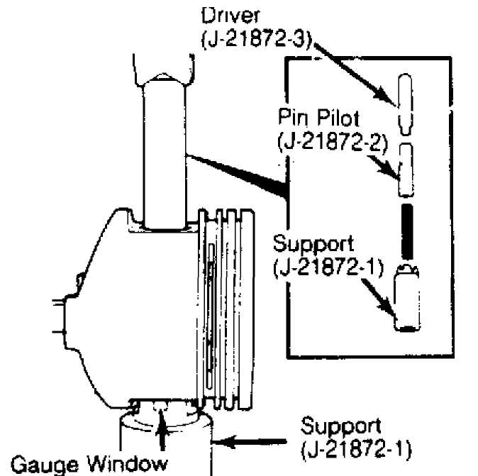
Fig. 7: Removing & Installing Piston Pin Courtesy of Chrysler Corp.
Fitting Pistons
Measure cylinder bore 2 5/16" (59 mm) below top of bore.
Note
locations of arrow on piston crown and oil squirt
hole in
connecting rod. Position piston and rod assembly on support.
See
Fig. 7. Press piston pin from piston.
Discard pin.Piston pin
CANNOT be reused
after removal. Inspect piston pin bore in connecting
rod for
nicks or burrs and remove as necessary.
Clean
piston pin bore and replacement piston pin. Piston
and piston pin
must be at room temperature when measuring fit. Piston
pin should
fall through piston at room temperature. If pin jams in pin
bore,
replace piston.
Position
piston on support so that arrow on piston crown
will point to
front of engine and connecting squirt hole will face
camshaft
when installed. Insert piston pin through piston pin bore and
into
connecting rod pin bore.
Press
pin through rod and piston until pilot aligns with
mark
on support. Pin should be centered in rod. Piston pin
installation
requires approximately 2000 lbs. (900
kg) of force.
Replace
connecting rod if noticeably less force is required, or if rod
moves
on pin.
Measure piston diameter at right angle to piston pin at center line of pin. Piston clearance is difference between measurements. Pistons up to .004" (.10 mm) undersize may be enlarged by knurling or shot peening. Replace pistons if clearance is greater than .004" (.10 mm) or more.
Piston Rings
Install piston rings. DO NOT interchange piston rings. Top ring has a Gray scraping surface; second ring is Black. Ensure ring end gap and side clearance are within specifications. Install compression rings with dot(s) on ring surface toward top of piston. Position ring end gaps in specified area. Ring gaps may vary 20 degrees from locations illustrated. See Fig. 8. Also see PISTONS, PINS & RINGS table under ENGINE SPECIFICATIONS.
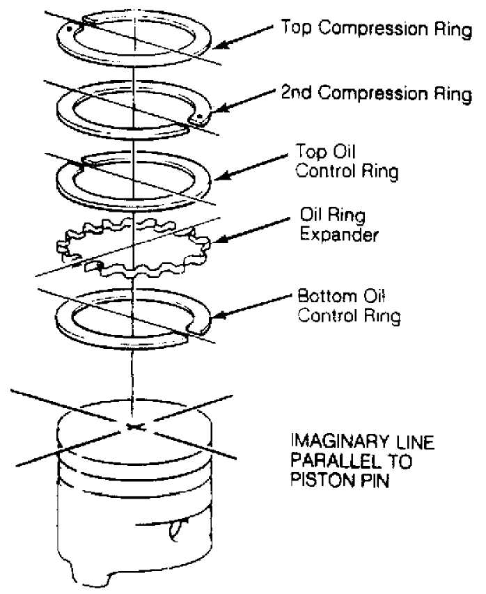
Fig. 8: Positioning Piston Ring Gaps Courtesy of Chrysler Corp.
Rod Bearings
1) Inspect bearings for wear or damage. Replace as necessary.
Using Plastigage, check bearing clearance. See CRANKSHAFT, MAIN & CONNECTING ROD BEARINGS table under ENGINE SPECIFICATIONS. Bearings are available for standard and undersize applications.
2) If necessary, different size upper and lower bearings may be combined to obtain correct oil clearance. Tighten bolts to specification. Check rod side play. Rotate crankshaft to ensure freedom of movement. See TORQUE SPECIFICATIONS table. See CRANKSHAFT, MAIN & CONNECTING ROD BEARINGS table.
NOTE: Never combine bearing inserts that differ by more than .001" (.03 mm) in size. Odd size inserts must be on bottom (rod cap) side.
Crankshaft & Main Bearings
1) Inspect
bearings for damage or wear. Replace as necessary.
Using
Plastigage, measure bearing clearance. See CRANKSHAFT, MAIN
&
CONNECTING ROD BEARINGS table
under ENGINE SPECIFICATIONS. Bearings
are
available in standard and undersize. If necessary, different
size
upper and lower bearings may be installed to obtain correct
oil
clearance. Lubricate bearings before
installation.
NOTE: If different size bearings are installed, the odd size
bearings must all be uniform in location (upper or lower). Never combine bearing inserts that differ by more than .001" (.03 mm).
2) Install
upper bearing inserts. Install bearing caps and
lower
inserts. Tighten bearing caps No. 1, 3, 4 and
5 in 3 stages
to
specification. Pry crankshaft to front or rear and tighten
bolts for
cap No. 2 to
specification in 3 stages. Rotate
crankshaft to ensure
freedom of movement after tightening each
cap. See the
TORQUE SPECIFICATIONS table. See CRANKSHAFT, MAIN & CONNECTING ROD BEARINGS table.
Thrust Bearing
Check crankshaft end play. If end play is not within
specification, replace bearing No. 2. If end play is still not within specification, replace crankshaft. See CRANKSHAFT, MAIN & CONNECTING ROD BEARINGS table under ENGINE SPECIFICATIONS.
Cylinder Block
Measure
cylinder bore diameter crosswise to cylinder block
near top of
bore. Repeat measurement at bottom of bore. Subtract
smaller
diameter from larger diameter to determine taper.
Repeat
measurements for each cylinder.
Repeat
measurements with measuring device rotated 120
degrees.
Repeat this step for a total of 3 measurements.
Cylinder out-
of-round is the
difference between measurements. Repeat for each
cylinder.
Bore
and hone cylinders for oversize pistons if taper or
out-of-round
exceeds specification. Move hone up and down to provide a
60-degree
crosshatch pattern. DO NOT use a rigid hone or exceed 10
strokes
per cylinder. See CYLINDER BLOCK table under
ENGINE SPECIFICATIONS.
LUBRICATION
ENGINE OILING
A distributor-driven pump supplies oil through a full-flow oil filter to an oil gallery on right side of block and intersecting lifter bores. Oil then flows to camshaft and crankshaft bearings. The
rocker arms receive oil through the push rods and lifters.
Crankcase Capacity
Crankcase capacity is 4 qts. (3.8L) with oil filter change.
Oil Pressure
Normal oil pressure should be 25-35 psi (1.8-2.5 kg/cm) at 800 RPM or 37-75 psi (2.6-5.3 kg/cm) at 1600 RPM. Oil pressure relief occurs at 75 psi (5.3 kg/cm).
OIL PUMP
Removal & Disassembly
Remove oil pump retaining bolts. DO NOT move oil pick-up pipe in pump body. If oil pick-up pipe is moved, pick-up pipe must be replaced to ensure an airtight seal. Remove pump cover. Disassemble pump.
Inspection
Inspect
for wear and damage. Place Plastigage across full
width
of each gear. Temporarily install cover, and tighten bolts to
70
INCH lbs. (8 N.m).
Remove cover. Examine Plastigage to determine
end
clearance.
Rotate
gears, and measure clearance between each tooth and
oil pump
body, directly opposite point of mesh. Replace oil pump if
not
within specification. See OIL PUMP SPECIFICATIONS table.
OIL PUMP SPECIFICATIONS TABLE
Application In. (mm)
Gear End Clearance 002-.006 (.05-.15)
Gear-to-Body Clearance 002-.004 (.05-.10)
Reassembly & Installation
Apply
sealant to pick-up pipe and pump cover area prior to
installation.
To install pick-up tube, use Pipe Installer (7624).
Ensure
pick-up pipe support bracket is aligned with pump cover bolt.
If
relief valve is replaced, ensure replacement valve is same
diameter
as that removed.
Fill pump
cavity with petroleum jelly. Install cover.
Tighten cover bolts
to specification. Check pump gears for freedom of
rotation.
Install new gasket and oil pump. Tighten retaining bolts
to
specification. See TORQUE SPECIFICATIONS table.
TORQUE SPECIFICATIONS
TORQUE SPECIFICATIONS TABLE
Application Ft. Lbs. (N.m)
Camshaft Sprocket Bolt 80 (108)
Connecting Rod Cap Nuts 33 (45)
Cylinder Head Bolts (1)
Stage 1 22 (30)
Stage 2 45 (61)
Stage 3 (2) 110 (149)
Drive Plate-To-Converter Bolts 40 (54)
Exhaust Manifold Bolts (3)
Bolt No. 1 30 (41)
Bolt No. 2-5 23 (31)
Nut No. 6 & 7 30 (41)
Fan Bolts 18 (24)
Flexplate-To-Crankshaft Bolts (4) 50 (68)
Flywheel-To-Crankshaft Bolts (4) 50 (68)
Intake Manifold Bolts (3)
Bolt No. 1 30 (41)
Bolt No. 2-5 23 (31)
Nut No. 6 & 7 30 (41)
Main Bearing Cap Bolts
Stage 1 40 (54)
Stage 2 70 (95)
Stage 3 80 (108)
Oil Pump Retaining Bolts
Long 17 (23)
Short 10 (14)
Oxygen (O2) Sensor 23 (31)
Pulley-To-Vibration Damper Bolts 20 (27)
Rocker Arm Bolts 21 (28)
Starter Bolts 33 (45)
Throttle Body-To-Intake Bolts 10 (14)
Vibration Damper Bolt (5) 80 (108)
Water Pump Bolts 25 (34)
INCH Lbs. (N.m)
Front Cover-To-Block Bolts 62 (7)
Oil Pan Bolts
1/4" X 20 114 (13)
5/16" X 18 156 (18)
Oil Pump Cover Bolts 70 (8)
Valve Cover Bolts 85 (9)
- Tighten in sequence. See Fig. 3.
- All except bolt No. 7. Tighten bolt No. 7 to
100 ft. lbs. (136 N.m).
- Tighten bolts in sequence. See Fig. 2.
- Tighten to specification and an additional 60 degrees.
- With bolt cleaned and threads lubricated with oil.
ENGINE SPECIFICATIONS
GENERAL ENGINE SPECIFICATIONS
GENERAL ENGINE SPECIFICATIONS TABLE
Application Specification
Displacement 150 Cu. In. (2.5L)
Bore 3.88" (98.5mm)
Stroke 3.19" (81.0mm)
Compression Ratio
Cherokee 9.2:1
Wrangler 9.1:1
Fuel System PFI
Horsepower @ RPM
Cherokee 130 @ 5250
Wrangler 123 @ 5250
Torque Ft. Lbs. @ RPM
Cherokee 149 @ 3000
Wrangler 139 @ 3250
CRANKSHAFT, MAIN & CONNECTING ROD BEARINGS SPECS
CRANKSHAFT, MAIN & CONNECTING ROD BEARINGS SPECS TABLE
Application
In. (mm)
Crankshaft
End Play 0015-.0065 (.038-.165)
Runout ( 1)
Main Bearings
Journal Diameter 2.4996-2.5001 (63.490-63.503)
Journal Out-Of-Round 0005 (.013)
Journal Taper 0005 (.013)
Oil Clearance 0010-.0025 (.025-.063)
Connecting Rod Bearings
Journal Diameter 2.0934-2.0955 (53.172-53.226)
Journal Out-Of-Round 0005 (.013)
Journal Taper 0005 (.013)
Oil Clearance 0015-.0025 (.038-.063)
(1) - Information not available from manufacturer.
CONNECTING RODS SPECIFICATIONS
CONNECTING RODS SPECIFICATIONS TABLE
Application
In. (mm)
Bore Diameter
Pin Bore 9288-.9298 (23.591-23.617)
Crankpin Bore 2.2080-2.2085 (56.083-56.096)
Center-To-Center Length 6.123-6.127 (155.52-155.63)
Maximum Bend 003 (.08)
Maximum Twist 006 (.15)
Side Play 010-.019 (.25-.48)
PISTONS, PINS & RINGS SPECIFICATIONS
PISTONS, PINS & RINGS SPECIFICATIONS TABLE Application
In. (mm)
Piston
Clearance 0013-.0021 (.033-.053)
Diameter ( 1)
Pins
Diameter 9306-.9307 (23.637-23.640)
Piston Fit 0003-.0007 (.007-.018)
Rod Fit Press Fit
Rings
No. 1 & 2
End Gap 010-.020 (.25-.51)
Side Clearance 0017-.0032 (.043-.081)
No. 3 (Oil)
End Gap 015-.055 (.38-1.40)
Side Clearance 001.010 (.03-.24)
(1) - Information is not available from manufacturer. Replace pistons if piston clearance exceeds .004" (.10 mm).
CYLINDER BLOCK SPECIFICATIONS
CYLINDER BLOCK SPECIFICATIONS TABLE
Application In. (mm)
Cylinder Bore
Standard Diameter 3.875-3.877 (98.42-98.48)
Maximum Taper 001 (.03)
Maximum Out-Of-Round 001 (.03)
Minimum Deck Height 9.320 (236.73)
Maximum Deck Warpage 008 (.20)
VALVES & VALVE SPRINGS SPECIFICATIONS
VALVES & VALVE SPRINGS SPECIFICATIONS TABLE
Application Specification
Intake Valves
Face Angle 45
Head Diameter 1.90" (48.3 mm)
Minimum Margin 031" (.79 mm)
Minimum Refinish Length 4.889" (124.18mm)
Stem Diameter 311-.312" (7 . 89-7 . 92 mm)
Valve Tip Maximum Refinish 010" (.25 mm)
Exhaust Valves
Face Angle 45 °
Head Diameter 1.50" (38.1 mm)
Minimum Margin 031" (.79 mm)
Minimum Refinish Length 4.927" (125.15 mm)
Stem Diameter 311-.312" (7 . 90-7 . 92 mm)
Valve Tip Maximum Refinish 010" (.25 mm)
Valve Springs
Free Length 2.0" (51 mm)
Installed Height (1)
Out-Of-Square (1)
Pressure (2)
Valve Closed 80-90 @ 1.64 (36.3-40.8 @ 40.8)
Valve Open 200 @ 1.216 (90.7 @ 30.9)
- Information is not available from manufacturer.
- Lbs. @ In. (kg @ mm).
CYLINDER HEAD SPECIFICATIONS
CYLINDER HEAD SPECIFICATIONS TABLE
Application Specification
Cylinder Head Height ( 1)
Maximum Warpage 008" (.20 mm)
Valve Seats Intake Valve
Seat Angle 44 . 5-45 °
Seat Width 040-.060" (1.02-1.52 mm)
Maximum Seat Runout 0025" (.063 mm)
Exhaust Valve
Seat Angle 44.5-45 °
Seat Width 040-.060" (1.02-1.52 mm)
Maximum Seat Runout 0025" (.063 mm)
Seat Bore Diameter ( 1)
Valve Guides Intake Valve
Valve Guide I.D 313-.314" (7.95-7.98 mm)
Valve Stem-To-Guide
Oil Clearance 001-.003" (.03-.08 mm)
Exhaust Valve
Valve Guide I.D 313-.314" (7.95-7.98 mm)
Valve
Stem-To-Guide
Oil Clearance
001-.003"
(.03-.08 mm)
(1) - Information is not available from manufacturer. CAMSHAFT SPECIFICATIONS
CAMSHAFT SPECIFICATIONS TABLE
Application
In. (mm)
Bore Diameter ( 1)
End Play (2) 0 (0)
Journal Diameter
No. 1 2.029-2.030 (51.54-51.56)
No. 2 2.019-2.020 (51.28-51.31)
No. 3 2.009-2.010 (51.03-51.05)
No. 4 1.999-2.000 (50.78-50.80)
Journal Runout ( 3)
Lobe Height ( 1)
Lobe Lift 265 (6.73)
Oil Clearance 001-.003 (.03-.08)
- Information is not available from manufacturer.
- Engine running.
- Information is not available from manufacturer.
Manufacturer specifies .001" (.03 mm) maximum base circle runout.
VALVE LIFTERS SPECIFICATIONS
VALVE LIFTERS SPECIFICATIONS TABLE
Application
In. (mm)
Bore Diameter 9055-.9065 (22.987-23.025)
Lifter Diameter 9040-.9045 (22.962-22.974)
Oil Clearance 001-.002 (.03-.05)