1993 Jeep Cherokee
1993 Drive Axles - Drive Shafts & Universal Joints Cherokee, Grand Cherokee, Grand Wagoneer, Wrangler
DESCRIPTION
Drive shafts are balanced, one-piece, tubular steel shafts with universal joints at each end. Single Cardan universal joints contain a spider, 4 bearing caps with needle bearings, seals and clips. Double Cardan universal joints contains 2 spiders joined together, 8 bearing caps with needle bearings, seals and clips. See Fig. 1.
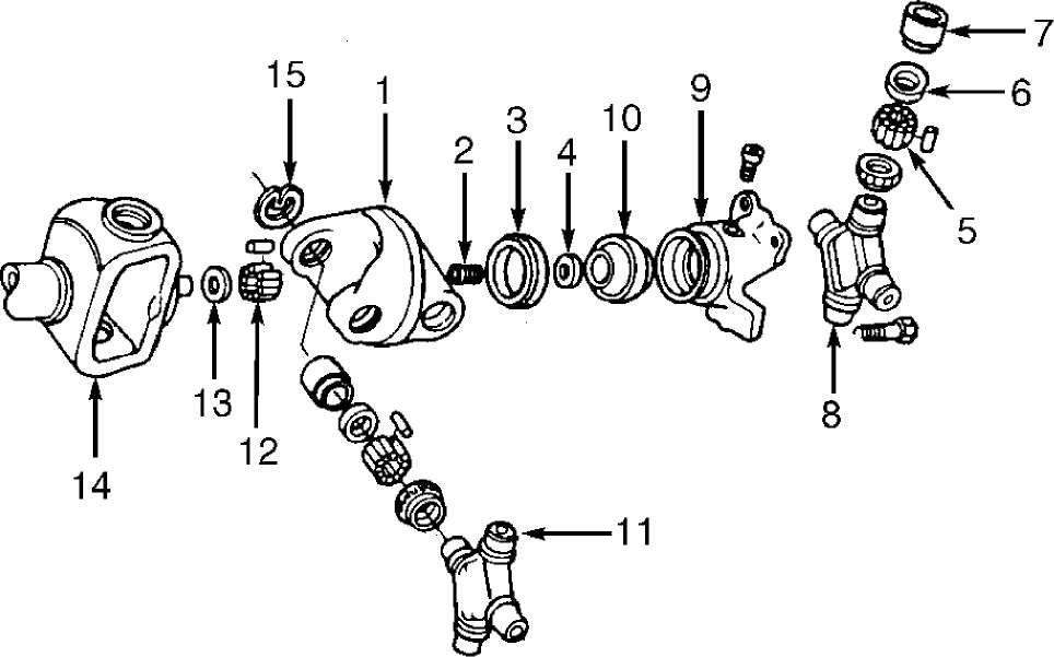
Link Yoke
Socket Spring
Socket Ball Retainer
Thrust Washer
Needle Bearings
Seal
Bearing Cap
Rear Spider
Socket Yoke
10. Socket Ball
Front Spider
Needle Bearings
Thrust Washer
Drive Shaft Yoke
Retaining Clip
92A21840
Fig. 1: Exploded View Of Double Cardan Universal Joint Courtesy of Chrysler Corp.
INSPECTION
VIBRATION
Tires & Wheels
Check tire inflation and wheel balance. Check for foreign objects in tread, damaged tread, mismatched treads or tire sizes. Check for tires that are out of round. Replace or repair as necessary.
Engine & Transmission Mounts
Tighten mounting bolts. Replace mounts if soft or separated.
Drive Shaft
Check shaft for damage or dents. Check for undercoating on shaft. If present, clean shaft.
Universal Joints
Check for defective or damaged "U" joints. Check for loose bolts and worn bearings.
DRIVE SHAFT RUNOUT
Remove any dirt from area around shaft where dial indicator is placed. Measure shaft runout about 3" from weld-seam on each end of shaft. With dial indicator mounted perpendicular to drive shaft, rotate shaft several times. Record runout measurement. Repeat the procedure at the opposite end and center of the drive shaft. See DRIVE SHAFT RUNOUT table. If runout is not equal to or less than specification, replace drive shaft.
DRIVE SHAFT RUNOUT TABLE
Application In. (mm)
Front & Rear of Shaft 010 (.25)
Center of Shaft 015 (.38)
DRIVE SHAFT ANGLE
NOTE: If drive shaft angle is excessive, vibration may result.
Check condition of springs, engine and transmission
mounts. Ensure all mounting fasteners are tight. To ensure proper
riding height, fuel tank should be full and vehicle should be empty of
cargo. Raise and support vehicle so suspension bears weight of vehicle
and wheels can rotate freely.
Remove clips from "U" joint cap bore. Ensure bearing caps
are clean. Joint bearing cap to be measured must be straight down.
Place Inclinometer (J-23498-A) on bearing cap. Center bubble in sight
glass. Record measurement. Rotate drive shaft 90 degrees. Repeat
procedure. Subtract smaller figure from larger figure to obtain "U"
joint angle.
Repeat procedure outlined in step 2) at opposite end of
drive shaft. Compare "U" joint angle measurements. Difference of "U"
joint angles MUST be within specification. See UNIVERSAL JOINT ANGLE
table. If not with specification, adjust "U" joint angle. See
SHAFT ANGLE under ADJUSTMENTS.
UNIVERSAL JOINT ANGLE TABLE
Application Specification
Double Cardan Universal Joint 0-2.5 ┬░
Single Cardan "U" Joint 0-1.5
ADJUSTMENTS
SHAFT ANGLE
Front - Except Wrangler
Adjust drive pinion gear shaft angle "A" at the lower
suspension arms with shims. Adding shims will decrease pinion gear
shaft angle "A" but will increase caster angle. See Fig. 2.
Adjustment of angle "A" is more important than caster
angle. When angle "A", angle "B" and vehicle height are correct, angle
"C" will also be correct.
 90B04353
Fig. 2: Front Drive Shaft Angle Courtesy of Chrysler Corp.
(Except Wrangler)
Front - Wrangler
Raise vehicle and place jack stands under frame. Place a
hydraulic jack under differential housing. Raise jack to support
weight of axle.
Loosen spring "U" bolt nuts, and install tapered shims
between springs and axle spring bracket to correct angle. Tighten
spring "U" bolt nuts to 52 ft. lbs. (70 N.m) for Cherokee or 100 ft.
lbs. (136 N.m) for all others.
NOTE: Adjustment procedure for rear shaft angle not available from manufacturer.
OVERHAUL
NOTE: If joints are rusted or corroded, before disassembly.
apply penetrating oil
SINGLE CARDAN UNIVERSAL JOINT
Disassembly
Scribe or paint marks on yokes and drive shaft for reassembly reference. Remove bearing cap retainer clips. Using sockets and vise as a press, remove bearing caps retaining spider to drive shaft and yoke. Remove spider. Inspect caps for cracks or defective needle bearings. Check spider for scoring or excessive wear. If defective, replace complete unit.
CAUTION: DO NOT place shaft or slip yoke tube in vise. Clamp only the forged portions in vise.
Reassembly
Clean universal joint bores and yoke. Apply grease to yoke
bores, bearing caps, bearings and spider contact surfaces.
Place spider into yoke and tap bearing cap, seal and
bearings into yoke far enough to hold spider. Place a socket (smaller
than cap) on side cap and place in vise.
Tighten vise until caps are seated in yoke. Rotate spider
to make sure no binding occurs. Install cap clips and repeat procedure
on remaining caps.
DOUBLE CARDAN UNIVERSAL JOINT
NOTE: Double cardan universal joints are not serviceable. If defective, replace as an assembly.
Disassembly
1) Scribe or paint marks on yokes and drive shaft for
reassembly reference. Remove bearing cap retainer clips. Using sockets and vise as a press, remove bearing caps retaining front spider to link yoke. Remove drive shaft yoke from link yoke. See Fig. 1.
2) Remove bearing caps retaining rear spider in link yoke.
Remove rear spider and socket yoke from link yoke. Remove bearing caps
retaining front spider in drive shaft yoke. Remove front spider from
drive shaft yoke.
Inspection
Check all component for cracks, scores and excessive looseness. If any defect is found, replace complete "U" joint assembly.
Reassembly
Ensure alignment of reference marks made during
disassembly. Use extreme pressure (EP) lithium grease to aid in
assembly. Place bearing caps on both ends of rear spider and secure
with tape. Spider will mate with transfer case yoke. Assemble socket
yoke and rear spider.
Install rear spider and socket yoke in link yoke. Insert
bearing caps in yoke bores. Using sockets and a vise, press caps into
bores Install retaining clips. Install front spider in drive shaft
yoke. Insert bearing caps in yoke bores. Press caps into bores.
Install retaining clips.
Install thrust washer on drive shaft yoke. Align and
install ball socket on drive shaft yoke. Install front spider in link
yoke. Insert bearing caps in yoke bores. Press caps into bores.
Install retaining clips. Check "U" joint for binding. Install drive
shaft.