A/C COMPRESSOR OVERHAUL
1993 Jeep Cherokee
1993 GENERAL SERVICING Compressor Servicing
REFRIGERANT OIL & REFRIGERANT SPECIFICATIONS
NOTE: Due to late changes, always refer to underhood A/C
Specification Label in engine compartment or A/C compressor label while servicing A/C system. If A/C Specification Label and specifications in table differ, use label specifications.
REFRIGERANT OIL & REFRIGERANT CAPACITY TABLE (CARS)
(1) Oil Refrigerant
Application Ounces Ounces
Chrysler Corp.
All FWD Cars (2) 7.3 32
Concorde, Intrepid
& Vision 5.0 28
Laser & Talon 5.0 33
- Total system capacity, unless otherwise noted.
- With fixed displacement compressor. Use 8.7 ounces with
variable displacement compressor.
REFRIGERANT OIL & REFRIGERANT CAPACITY TABLE (LIGHT TRUCKS/VANS)
(1) Oil Refrigerant
Application Ounces Ounces
Chrysler Corp. (Except Jeep)
Dakota 4.6 44
FWD Vans (2)
With Rear Unit 13.4 50
Without Rear Unit 6.7 36
Pickup & Ramcharger 4.6 44
RWD Vans
With Rear Unit 9.3 65
Without Rear Unit 7.3 45
Jeep
Cherokee 4.6 38
Grand Cherokee (2) 8.0 28
Wrangler 4.6 32
- Total system capacity, unless otherwise noted.
- Models use R-134a refrigerant and PAG (ND8) Refrigerant Oil
(Part No. 82300102).
COMPRESSOR APPLICATIONS
NOTE: Due to late changes, always refer to underhood A/C
Specification Label in engine compartment or A/C compressor label while servicing A/C system. If A/C Specification Label and specifications differ, use label specifications.
COMPRESSOR APPLICATIONS TABLE (CARS)
Application Compressor
Chrysler Corp.
Concorde, Intrepid, Laser,
Talon & Vision Nippondenso 10PA17 10-Cyl.
Except Concorde, Intrepid,
Laser, Talon & Vision Nippondenso 6C-17 6-Cyl.,
Nippondenso 10PA17 10-Cyl.,
Sanden TR-105 10-Cyl.,
Sanden SD-709P 7-Cyl.
COMPRESSOR APPLICATIONS TABLE (LIGHT TRUCKS & VANS)
Application Compressor
Chrysler Corp. (Except Jeep)
Dakota, Pickup & Ramcharger Sanden SD-709 7-Cyl.
FWD Vans Nippondenso 10PA17 10-Cyl.
RWD Vans Sanden TR-105 10-Cyl.
(1) - Series codes are determined by fifth character of VIN code.
BODY DESIGNATIONS
BODY DESIGNATIONS TABLE (CHRYSLER CORP. CARS)
Body Designation (1) Model
"A" Body Acclaim, LeBaron Sedan & Spirit
"C" Body Dynasty & New Yorker
"G" Body Daytona
"J" Body LeBaron Convertible/Coupe
"LH" Body Concorde, Intrepid & Vision
"P" Body Shadow & Sundance
"S" Body Laser & Talon
"Y" Body Fifth Avenue & Imperial
(1) - Body codes are determined by fifth character of VIN code.
BODY
DESIGNATIONS TABLE (CHRYSLER CORP. LIGHT TRUCKS &
VANS)
Model Designation
Caravan "D" & "K" Series
Dakota "N" Series
Pickups (Full Size) "D" & "W" Series
Ramcharger "AD" & "AW" Series
Town & Country "Y" Series
Vans (Full Size) "B" Series
Voyager "H" & "P" Series
NIPPONDENSO 6C-17 6-CYLINDER
CLUTCH ASSEMBLY
Removal
1) Disconnect negative battery cable. Loosen and remove
compressor drive belt. Disconnect clutch coil lead. With refrigerant lines attached, remove compressor mounting bolts and position compressor for service.
Using
Clutch Hub Holder (6355), remove
crankshaft nut.
Using Clutch Hub Puller (6354), remove
clutch hub and hub clearance
shims.
Remove
snap ring and pulley assembly. Remove snap ring and
clutch coil
assembly.
Installation
Align hole
in back of clutch coil with pin in compressor
housing. Ensure
clutch coil lead is properly routed. To complete
installation,
reverse removal procedure.
Tighten
crankshaft nut. Using a feeler gauge, check clutch
plate-to-pulley
clearance. Clearance should be .020-.035" (.51-.89
mm). If clearance is incorrect, add or remove shims as necessary.
SHAFT SEAL
Removal
Discharge
A/C system using approved refrigerant
recovery/recycling
equipment. Remove compressor. Drain oil from
compressor, and
measure amount of oil drained. Remove compressor
clutch assembly.
Remove
compressor crankshaft key. Remove felt packing from
nose of front
cover. Clean area around seal.
3) Remove
shaft seal snap ring. Using Seal Remover/Installer
(6429),
remove seal from compressor.
Installation
Lubricate
NEW shaft seal with refrigerant oil. Install
Seal
Protector (6231) over compressor shaft.
Using flat end of Seal
Remover/Installer
(6429), install shaft seal until seal
seats in
housing.
Install
NEW shaft seal snap ring. Install clutch assembly.
Using
new refrigerant oil, add same amount of oil to compressor as
was
drained from it. Install compressor. Evacuate and recharge
system.
Perform leak test. See LEAK
TESTING in A/C GENERAL SERVICING
PROCEDURES
article in the AIR CONDITIONING & HEAT
Section.
NIPPONDENSO 10PA17 & 10PA17A 10-CYLINDER
CLUTCH ASSEMBLY
Removal
Remove
and discard compressor shaft bolt. Remove clutch
plate
and shims. Tap on clutch plate using a soft-faced hammer
(if
necessary).
Remove
pulley assembly snap ring. Remove pulley assembly.
Remove snap
ring, and disconnect clutch coil lead. Remove clutch coil.
Installation (Chrysler)
Install
clutch coil so pin in back of coil aligns with
hole in front
housing. Install snap ring with beveled side away from
compressor.
Install
pulley assembly. Install snap ring with beveled
side away from
compressor. If reusing original clutch plate and
pulley, old
shims can be used.
If
using new components, install several shims so shim
pack
thickness is .10" (2.5 mm).
Install clutch plate and hold it
tightly
against shims.
Using feeler gauge, measure air gap between clutch plate
and pulley surface. On Laser and Talon, clearance should be .014-.026" (.36-.66 mm). On all models except Laser and Talon, clearance should be .020-.035" (.51-.89 mm). Adjust shim thickness to obtain correct clearance. Install NEW compressor shaft bolt and tighten it to 13 ft. lbs. (18 N.m).
5) Once compressor shaft bolt is tightened, recheck clearance between clutch plate and pulley surface in 4 places. Readjust clearance if necessary.
NOTE: On Chrysler models, ensure voltage is correct after
installing new clutch. Cycle clutch on for 5 seconds and off for 5 seconds. Repeat cycle 20 times with A/C on, blower fan on high speed and engine speed at 1500-2000 RPM.
SHAFT SEAL
Removal
Discharge
A/C system using approved refrigerant
recovery/recycling
equipment. Remove compressor. Drain oil from
compressor, and
measure amount drained. Remove clutch assembly.
Remove
felt dust seal and dust seal retainer from front
head.
See Fig. 1. Remove shaft seal snap ring.
Position front head
(nose up) on cardboard placed on a flat surface. Using brass drift, press shaft seal from front head.
Installation
Lubricate
new shaft seal with refrigerant oil. DO NOT
touch sealing
surfaces. Press seal into front head, and install snap
ring.
Install felt dust seal and dust seal retainer.
Lubricate
Shaft Seal Protector (J-34614) and front head
"O"
ring with refrigerant oil. Install shaft seal
protector on
crankshaft. Install a new
front head "O" ring on cylinder
assembly.
Install
front head on cylinder assembly. Ensure dowel pins
are aligned.
Use care when guiding shaft seal protector through seal
opening.
Remove shaft seal protector.
Install
through bolts using NEW brass washers. Diagonally
tighten
bolts to 19 ft. lbs. (26 N.m).
Using INCH-lb. torque wrench,
check compressor shaft rotating
torque. Rotating torque should be 26
INCH
lbs. (3 N.m). Install clutch assembly.
Using
new refrigerant oil, add same amount of oil to
compressor as was
drained from it. Install compressor. Evacuate and
recharge
system. Perform leak test. See LEAK TESTING in A/C GENERAL
SERVICING
PROCEDURES article in the AIR CONDITIONING & HEAT
Section.
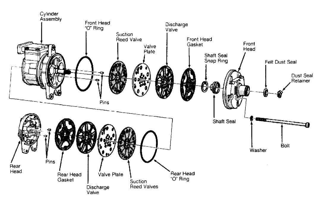
Fig. 1: Exploded View Of Compressor (Nippondenso 10PA17, 10PA17A & 10PA20 10-Cylinder) Courtesy of Ford Motor Co.
SANDEN SD-709 & SD-709P 7-CYLINDER
CLUTCH ASSEMBLY
Removal
Using
Spanner (6462), hold clutch and remove
compressor
shaft nut. Using Puller
(6461), remove clutch plate. Remove key
from
compressor shaft.
Remove
pulley snap ring. Install jaws of Puller (6141-1)
in
snap ring groove on pulley. Place Shaft Protector (6141-2)
on
compressor shaft.
Install
puller plate on jaws. Thread 2 bolts
through
puller plate into jaws. Remove
pulley from compressor. Remove snap
ring
and clutch coil.
Installation
Install
clutch coil and snap ring on compressor. Support
compressor on
rear mounting ears.
Using
hammer, Handle (6464) and Driver (6143),
install
pulley assembly. Ensure driver rests
on inner race of bearing when
installing pulley assembly. Install
snap ring.
Install
shims. Install key in compressor shaft. Using
hammer and Shaft
Protector (6141-2), install clutch plate
on
compressor shaft. Tighten compressor
shaft nut to 25-30 ft. lbs. (34-
41
N.m).
Using
feeler gauge, measure clearance between clutch plate
and
pulley assembly in several areas. Clearance should be .016-.031"
(.41-.79 mm). If clearance is not within specification, adjust shim thickness to obtain correct clearance.
SHAFT SEAL
Removal
Discharge
A/C system using approved refrigerant
recovery/recycling
equipment. Remove compressor. Drain oil from
compressor, and
measure amount drained. Remove clutch assembly.
Remove key
from shaft. Remove felt ring metal retainer and
felt ring. Using
small screwdriver, remove shims for clutch plate.
Ensure
area around seal is clean. Remove shaft seal snap
ring.
Using Shaft Seal Remover/Installer (6142), remove
shaft seal.
Install
Shaft Seal Remover/Installer (6144) into
shaft
seal. Press downward on shaft
seal remover/installer and rotate it to
engage
tangs with slots of shaft seal. Pull shaft seal from
compressor.
Installation
Install
Shaft Protector (6141-2) over compressor
shaft.
Coat shaft protector, new shaft
seal and shaft seal seat with
refrigerant oil. DO NOT touch
sealing surfaces of seal.
Place seal
on seal remover/installer, and twist tool to
hold seal. Install
seal in compressor, and twist tool in opposite
direction to
release seal. Remove seal remover/installer. Using shaft
seat
remover/installer, install shaft seat.
Install
snap ring. Tap on snap ring to ensure it seats in
groove (if
necessary). Install shims and new felt. To
install
remaining components, reverse
removal procedure. Using new refrigerant
oil,
fill compressor with the same amount of oil drained from it.
Install
compressor. Evacuate and recharge system. Perform leak test.
See
LEAK TESTING in A/C GENERAL SERVICING PROCEDURES article in the
AIR
CONDITIONING & HEAT Section.
SANDEN TR-105 10-CYLINDER
CLUTCH ASSEMBLY
Removal
1) Discharge A/C system using approved refrigerant
recovery/recycling equipment. Remove compressor. Install two6-mm bolts in holes of clutch plate. Hold 6-mm bolts while removing nut from end of compressor shaft.
Remove
clutch plate and shims. Tap clutch plate from
compressor
(if necessary). DO NOT pry between clutch
plate and pulley
to remove clutch
plate.
Remove
pulley assembly snap ring. Remove pulley assembly.
Disconnect
clutch coil lead. Scribe marks on clutch coil and
compressor for
installation reference. Remove snap ring and clutch
coil.
Installation
Install
clutch coil on compressor so locating pin engages
hole in clutch
coil. Install snap ring with beveled side away from
compressor.
Install
pulley assembly. Install snap ring with beveled
side away from
compressor. If reusing original clutch plate and
pulley, old
shims can be used.
If
new components are used, install several shims so shim
pack
thickness is .10" (2.5 mm).
Install clutch plate and hold it
tightly
against shims.
Using feeler gauge, measure air gap between clutch plate
and pulley surface. Proper clearance is .013-.025" (.33-.64 mm). Adjust shim thickness to obtain correct clearance. Tighten compressor shaft nut to 13 ft. lbs. (18 N.m).
5) Once compressor shaft nut is tightened, recheck clearance between clutch plate and pulley surface in 4 places. Readjust clearance if necessary. Install compressor. Evacuate and recharge system. Perform leak test. See LEAK TESTING in A/C GENERAL SERVICING PROCEDURES article in the AIR CONDITIONING & HEAT Section.
NOTE: After installing new clutch, ensure voltage is correct.
Cycle clutch on for 5 seconds and off for 5 seconds. Repeat cycle 20 times with A/C on, blower fan on high speed and engine speed at 1500-2000 RPM.
SHAFT SEAL
Removal
1) Discharge A/C system using approved refrigerant
recovery/recycling equipment. Remove compressor. Install two 6-mm bolts in holes of clutch plate. Hold 6-mm bolts while removing nut from end of compressor shaft.
Remove
clutch plate and shims. Tap clutch plate from
compressor
(if necessary). DO NOT pry between clutch
plate and pulley
to remove clutch
plate.
Insert
2 jaws of Bearing Remover/Installer (6533)
into
bearing groove.
Install retainer over jaws of bearing
remover/installer.
Tighten
pressure screw of bearing remover/installer
against compressor
shaft until bearing is removed.
Remove
felt washer from compressor. Remove shaft seal snap
ring. Engage
Seal Remover/Installer (6551) in slots of
seal case. Lift
seal from compressor.
Installation
Place
Seal Sleeve Protector (6552) over
compressor shaft.
Coat seal sleeve
protector and seal lip with refrigerant oil. Using
seal
remover/installer, install seal. Remove seal sleeve protector.
Install
shaft seal snap ring. Install felt washer. Install
bearing in
pulley. Using hammer with jaws and retainer of
bearing
remover/installer, drive bearing into pulley.
If
reusing original clutch plate and pulley, old shims can
be
used. If using new components, install several shims so shim
pack
thickness is .10" (2.5 mm).
Install clutch plate and hold it tightly
against
shims.
Using
feeler gauge, measure air gap between clutch plate
and pulley
surface. Proper clearance is .013-.025" (.33-.64
mm).
Adjust shim
thickness to obtain correct clearance. Tighten compressor
shaft
nut to 13 ft. lbs. (18 N.m).
Once
compressor shaft nut is tightened, recheck clearance
between
clutch plate and pulley surface in 4 places.
Readjust
clearance if necessary.