1993 Jeep Cherokee
GENERAL INFORMATION
Parasitic Load Explanation & Test Procedures
* PLEASE READ THIS FIRST *
This article is provided for general information only. Not all procedures apply to all makes and models.
GENERAL INFORMATION
The term Parasitic Load refers to electrical devices that continue to use or draw current after the ignition switch is turned to OFF position. This small amount of continuous battery draw is expressed in milliamps (mA). On Ford Motor Co. and General Motors vehicles produced after 1980, a typical Parasitic Load should be no more than 50 milliamps (0.050 amps).
Vehicles produced since 1980 have memory devices that draw current with ignition off for as long as 20 minutes before shutting down the Parasitic Drain. When Parasitic Load exceeds normal specifications, the vehicle may exhibit dead battery and no-start condition.
Follow test procedure for checking Parasitic Loads to
completion. A brief overview of a suggested test procedure is included along with some typical Parasitic Load specifications. Refer to the GENERAL MOTORS PARASITIC LOAD TABLE chart.
TESTING FOR PARASITIC LOAD
INTRODUCTION
CAUTION: Always turn ignition off when connecting or disconnecting battery cables, battery chargers or jumper cables. DO NOT turn test switch to OFF position (which causes current to run through ammeter or vehicle electrical system).
NOTE: Memory functions of various accessories must be reset after the battery is reconnected.
The battery circuit must be opened to connect test switch (shunt) and ammeter into the circuit. When a battery cable is removed, timer circuits within the vehicle computer are interrupted and immediately begin to discharge. If in doubt about the condition of the ammeter fuse, test it with an ohmmeter prior to beginning test. An open fuse will show the same reading (00.00) as no parasitic drain. Begin test sequence with the meter installed and on the 10-amp scale. Select lower scale to read parasitic draw.
TEST PROCEDURE USING TEST SWITCH
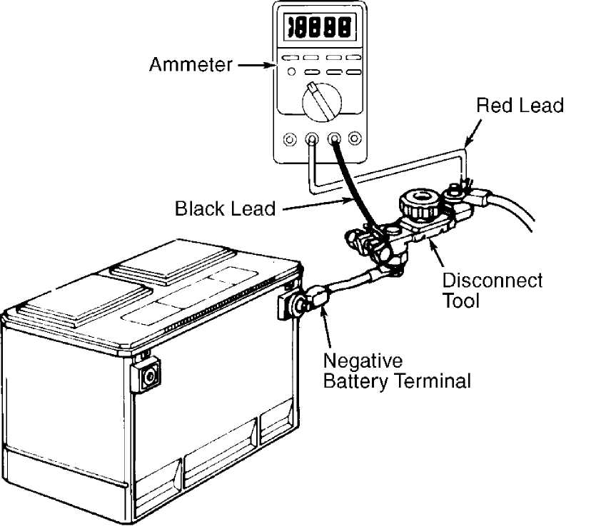
Turn ignition off. Remove negative battery terminal cable.
Install Disconnect Tool (J-38758) test switch male end to negative
battery cable. Turn test switch knob to OFF position (current through
meter). Install negative battery cable to the female end of test
switch.
Turn test switch knob to ON position (current through
switch). Road test vehicle with vehicle accessories on (radio, air
conditioner, etc.). After road test, turn ignition switch to LOCKED
position and remove key. Connect ammeter terminals to test switch
terminals. See Fig. 1. Select 10-amp scale.
Turn off all electrical accessories. Turn off interior
lights, underhood lamp, trunk light, illuminated entry, etc. To avoid
damaging ammeter or obtaining a false meter reading, all accessories
must be off before turning test switch knob to OFF position.
Turn test switch knob to OFF position to allow current to
flow through ammeter. If meter reads wrong polarity, turn test switch
to ON position and reverse leads. Turn test switch to OFF position.
Observe current reading. If reading is less than 2 amps, turn test
switch to ON position to keep electrical circuits powered-up.
Select low amp scale. Switch lead to the correct meter
position. Turn test switch to OFF position and compare results to
normal current draw. See the GENERAL MOTORS PARASITIC LOAD TABLE. If
current draw is unusually high for the vehicleÆs overall electrical
system, remove system fuses one at a time until current draw returns
to normal.
Turn test switch to ON position each time door is opened
or fuse is removed. Turn switch to OFF position to read current draw
value through meter. When the cause of excessive current drain has
been located and repaired, remove test switch and reconnect negative
battery cable to the negative battery terminal.
92F03911
Fig. 1: Connecting Kent-Moore Disconnect Tool (J-38758) Courtesy of General Motors Corp.
GENERAL MOTORS PARASITIC LOAD TABLE (MILLIAMPS)
|
Component |
Normal Draw 0.4 |
Maximum Draw 1.0 |
Time-Out (Minutes) |
|
Auto Door Lock |
1.0 |
1.0 |
|
|
Body Control Module |
3.6 |
12.4 2.7 |
20 |
|
Central Processing System ... |
1.6 |
||
|
Electronic Control Module ... |
5.6 |
10.0 |
|
|
Electronic Level Control ... . |
2.0 |
3.3 |
2.0 |
|
Heated Windshield Module . . . . |
0.3 |
0.4 |
|
|
HVAC Power Module |
1.0 |
1.0 |
|
|
Illuminated Entry |
1.0 |
1.0 |
1 |
|
Light Control Module |
0.5 |
1.0 |
|
|
Oil Level Module |
0.1 |
0.1 |
|
|
MultiŌĆöFunction Chime |
1.0 |
1.0 |
|
|
Pass Key Decoder Module |
.... 0.75 |
1.0 |
|
|
Power Control Module |
5.0 |
7.0 |
|
|
Retained Accessory Power .. . . |
3.8 |
3.8 |
|
|
Radio |
7.0 |
8.0 |
15 |
|
Twilight Sentinel Module .. . . |
1.0 |
1.0 |
|
|
Voltage Regulator |
1.4 |
2.0 |
|
INTERMITTENT PARASITIC LOAD PROBLEMS
Intermittent parasitic lad can occur because of a memory device that does not power down with ignition off. With an intermittent parasitic load, battery draw can be greater than 1.0 amp. To find and intermittent problem requires that an ammeter and Disconnect Tool (J-38758) test switch be connected and left in the circuit. See Fig. 1. Road test vehicle. After road test, turn ignition off and remove key.
Monitor the milliamps scale for 15-20 minutes after ignition is turned off. This allows monitoring memory devices to determine if they time out and stop drawing memory current. The test switch is needed to protect ammeter when the vehicles is started.
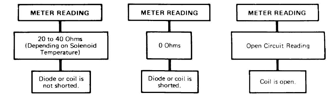
DIODE CHECK & SOLENOID TEST (GENERAL MOTORS)
Step 1) Select the X1 SCALE and zero the needle.
Step 2) Attach the POSITIVE SOLENOID LEAD (Red lead) to the POSITIVE METER LEAD and the NEGATIVE SOLENOID LEAD (Black lead) to the NEGATIVE METER LEAD.
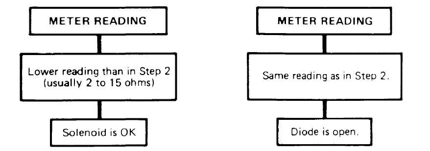
Step 3) Reverse the solenoid lead attachments.
92ąØ03ąŁ12
Fig. 2: Diode Check & Solenoid Test (General Motors) Courtesy of General Motors Corp.
QUAD DRIVER TEST (GENERAL MOTORS)
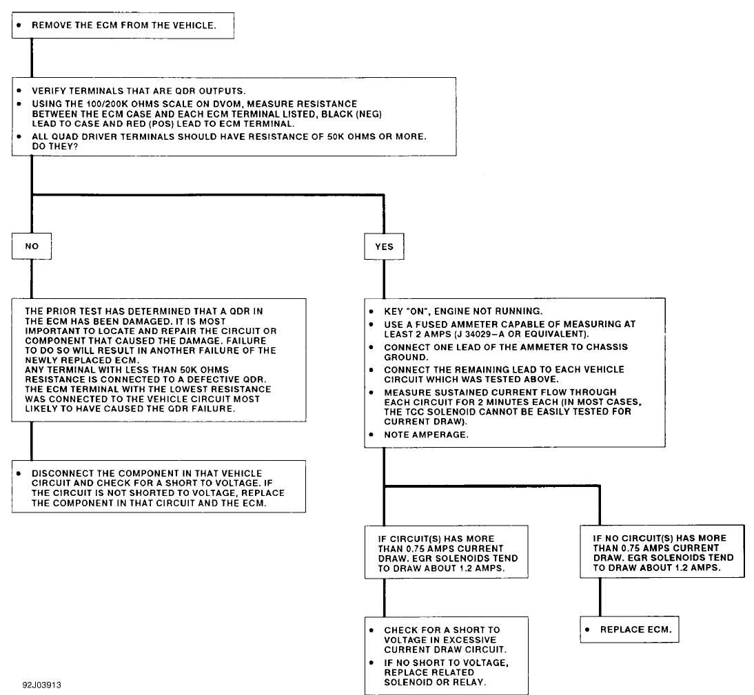
Fig. 3: Quad Driver Test (General Motors) Courtesy of General Motors Corp.