Ā
1993 Jeep Cherokee
WIRING DIAGRAMS
How To Use The Wiring Diagrams
WIRING DIAGRAMS
INTRODUCTION
The wiring diagrams and technical service bulletins,
containing wiring diagram changes, are obtained from the domestic and import manufacturers. These are checked for accuracy and are all redrawn into a consistent format for easy use.
All diagrams are arranged with the front of the vehicle at the left side of the first page and the rear of the vehicle at the right side of the last page. Accessories are shown near the end of the diagram.
Components are shown in their approximate location on the vehicle. Due to the constantly increasing number of components on vehicles today, it is impossible to show exact locations.
In the past, when cars were simpler, diagrams were simpler. All components were connected by wires, and diagrams seldom exceeded 4 pages in length. Today some wiring diagrams require more than 16 pages. It would be impractical to expect a service technician to trace a wire from page 1 across every page to page 16.
Removing some of the wiring maze reduces eyestrain and time wasted searching across several pages. Today, the majority of diagrams now follow a much improved format, which permits space for internal switch details and connector shapes.
Any wires that donÆt connect directly to their components are identified on the diagram to indicate where they go. There is a legend on the first page of each diagram, detailing component location. It refers you to sub-systems, using grid NUMBERS at the top and bottom of the page and grid LETTERS on each side. This grid system works in a manner similar to that of a road map.
HOW TO USE THE WIRING DIAGRAMS
On the first page of the diagram, you will find a listing
of major electrical components or systems. Locate the specific
component or system you wish to trace. A grid number and letter will
follow the componentÆs name.
Use the grid NUMBERS (arranged horizontally across the top
and bottom of each page) to find the page of the wiring diagram that
contains the component youÆre seeking. When you reach this page, use
the grid LETTERS on the side of the page to determine the componentÆs
vertical location.
Locate the circuit you need to service. The internals are
shown for switches and relays to assist you in understanding how the
circuit operates.
NOTE: In some of the newer wiring diagram articles in this
product, there is a Legend for the wiring diagrams that has been created to make locating components easier. For these articles, there will be a COMPONENT LOCATION MENU title in the article main menu. These articles will also have the original legend available on the first graphic.


Fig. 1: Identifying Tie-Off Symbols
If the wires are not drawn all the way to another
component (across several pages), a reference will tell you their
final destination.
Again, use the legend on the first page of the wiring
diagram to determine the grid number and letter of the referenced
component. You can then turn directly to it without tracing wires
across several pages.
The symbols shown in Fig. 1 are called tie-offs. The first
tie-off shown indicates that the circuit goes to the temperature
sensor, and is also a ground circuit.
The second symbol indicates that the circuit goes to a
battery positive parallel circuit. The third symbol leads to a
particular component and the location is also given.
The lines shown in Fig. 2 are called options. Which path
or option to take depends on what engine or systems the vehicle has.
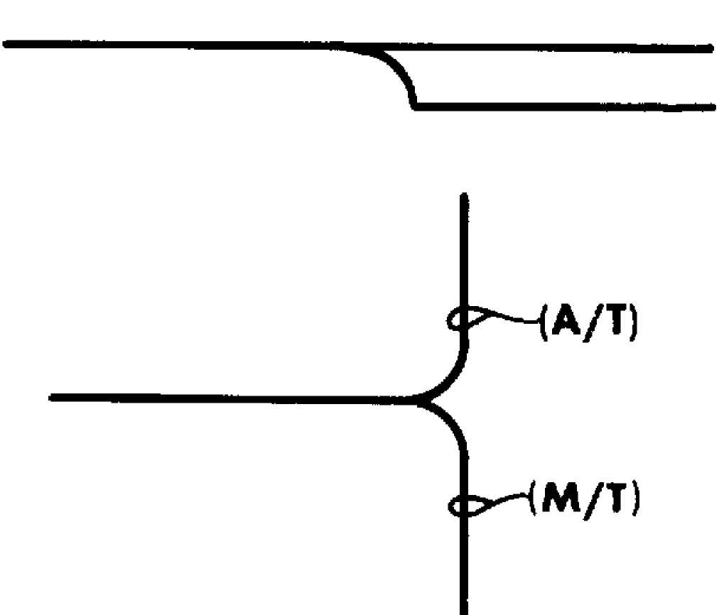
Fig. 2: Identifying Option Symbols
COLOR ABBREVIATIONS IDENTIFICATION
COLOR ABBREVIATIONS
Color Normal Optional
Black BLK BK
Blue BLU BU
Brown BRN BN
Clear CLR CR
Dark Blue DK BLU DK BU
Dark Green DK GRN DK GN
Green GRN GN
Gray GRY GY
Light Blue LT BLU LT BU
Light Green LT GRN LT GN
Orange ORG OG
Pink PNK PK
Purple PPL PL
Red RED RD
Tan TAN TN
Voilet VIO VI
White WHT WT
Yellow YEL YL
WIRING DIAGRAM SYMBOL IDENTIFICATION
NOTE: Standard wiring symbols are used on diagrams. The list below will help clarify any symbols that are not easily understood at a glance. Most components are labeled "Motor", "Switch" or "Relay" in addition to being drawn with the standard symbol.
WIRING DIAGRAM SYMBOLS
Views of the symbols used in the WIRING DIAGRAM articles are in the following graphics. See Figs. 3 through 25.

Fig. 3: Circuit Breaker

Fig. 4: Coil (Internal)
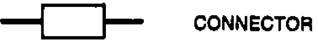
Fig. 5: Connector

Fig. 6: Diode (In-Line)
ŌĆö Ō¢║] Æ DIODE (Internal)
Fig. 7: Diode (Internal)
Fig. 7: Diode (Internal)
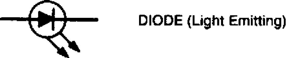
Fig. 8: Diode (Light Emitting)

Fig. 9: Defogger Grid

Fig. 10: Fuse

Fig. 11: Fusible Link

Fig. 12: Ground
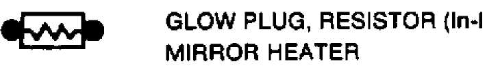
Fig. 13: Glow Plug Resistor (In-Line) or Mirror Heater

Fig. 14: Injector (Diesel) or Photocell (Gasoline)

Fig. 15: Internal Fuse, Thermal Limiter

Fig. 16: Lamp (Dual Element)

Fig. 17: Lamp (Single Element)

Fig. 18: Motor
Ō¢ĀVWWW- RESISTOR (Internal)
Fig. 19: Resistor (Internal)
Fig. 19: Resistor (Internal)

Fig. 20: Sensor, Thermistor

 Fig. 21: Solenoid

Fig. 22: Solid State Device, Transistor

Fig. 23: Switch (Internal)

Fig. 24: Two Pin Switch

Fig. 25: Variable Resistor or Potentiometer