ALTERNATOR - NIPPONDENSO
1993 Jeep Cherokee
1993 ELECTRICAL
Chrysler Corp. Alternators - Nippondenso
Cherokee, Grand Cherokee, Grand Wagoneer, Wrangler
DESCRIPTION
Charging system consists of a Powertrain Control Module (PCM), alternator, CHECK ENGINE light and battery. Voltage regulation is controlled within the PCM and cannot be serviced.
The PCM monitors charging system input and output to ensure correct operation. The PCM stores any charging system failures in memory and outputs fault code(s) when on-board diagnostics are entered.
The PCM monitors several different engine control system circuits. If a problem is detected within a monitored circuit, a fault code is stored in the PCM memory. The CHECK ENGINE light will illuminate and system may enter limp-in mode. In limp-in mode, engine controller compensates for component or circuit failure by using information from other sources until repairs are made.
NOTE: Fault codes remain in memory for 50 engine starts. Fault is erased from memory if failure does not reoccur.
ADJUSTMENTS
BELT TENSION
BELT ADJUSTMENT TABLE (1)
Application Lbs. (kg)
New Belt 180-200 (81.72-90.8)
Used Belt 140-160 (63.56-72.64)
(1) - Tension in lbs. (kg) using belt tension gauge.
TROUBLE SHOOTING
PRELIMINARY CHECKS
Visually inspect wiring and drive belts. If charging system is not working, ensure drive belts are properly tightened. Ensure 12 volts exist at alternator field terminal with ignition on. Ensure battery cables, alternator ground cables and alternator and terminal block connections are clean and tight. Ensure alternator field circuit is not grounded (overcharging).
UNSTEADY OR LOW CHARGING
Check for loose alternator belt, defective alternator, loose alternator ground wire or corroded battery terminals.
OVERCHARGING
Check for grounded alternator field wiring or faulty
alternator.
TESTING (ON-VEHICLE)
ALTERNATOR OUTPUT
Output Wire Resistance (Voltage Drop) Test
Ensure
battery is charged. Turn ignition off. Disconnect
negative
battery cable. Connect a 0-150 DC ammeter
and a voltmeter (0-
18 volts) to
vehicle’s charging system. See Fig. 1.
Connect a
carbon pile rheostat between battery terminals.
Ensure carbon
pile is in OFF position before connecting leads.
CAUTION: Alternator has 2 field terminals. In step 3), DO NOT connect jumper wire to alternator field terminal Dark Green/Orange wire.
Connect
one end of jumper wire to ground and other end to
alternator
field terminal Dark Green wire on rear side of alternator.
See
Fig. 2. Connect negative battery cable.
Start
engine. Reduce engine speed to idle. Adjust engine
speed
and carbon pile to maintain 20-amp current flow. Observe
voltmeter
reading. Voltage drop should be .5 volt or
less.
If
voltage drop is greater than .5 volt,
inspect, clean
and tighten all connections between alternator BAT
(B+) terminal and
positive battery
post. If wire resistance (voltage drop) is okay, test
is
complete. Remove all test equipment.
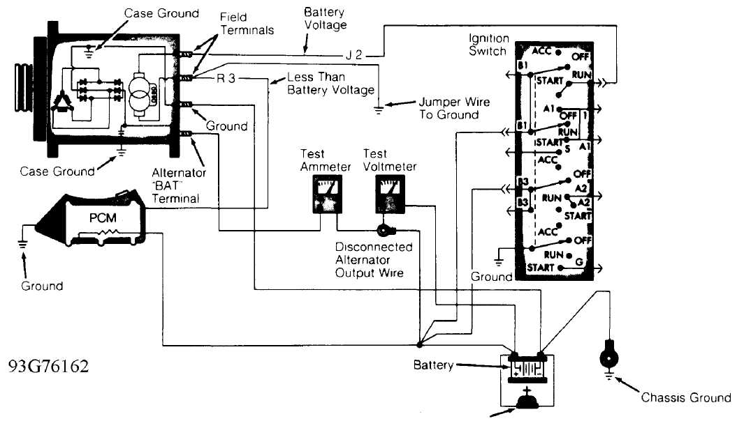
Carbon Pile Rheostat
Fig. 1: Testing Alternator Output Wire Resistance (Typical) Courtesy of Chrysler Corp.
Current Output Test
1) Ensure battery is charged. Turn ignition off. Disconnect
negative battery cable. Connect a 0-150 DC ammeter and a voltmeter (0-18 volts) to vehicle charging system. See Fig. 3.
2) Connect
a carbon pile rheostat between battery terminals.
Ensure
carbon pile is in OFF position before connecting leads.
CAUTION: Alternator has 2 field terminals. In step 3), DO NOT connect jumper wire to alternator field terminal Dark Green/Orange wire.
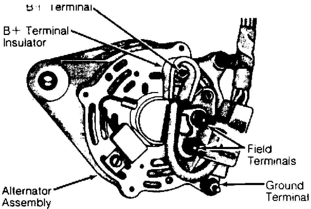
Fig. 2: Identifying Alternator Terminals Courtesy of Chrysler Corp.
Connect
one end of jumper wire to ground and other end to
alternator
field terminal Dark Green wire on rear side of alternator.
See
Fig. 2. Connect negative battery cable.
Start
engine and reduce engine speed to idle. Adjust
carbon pile and
engine speed until engine speed is 1250 RPM
and
voltmeter reads 15 volts. DO NOT
allow voltage to read greater than 16
volts.
Ammeter
should read within 10 amps of rating
listed on
back of alternator. If
reading is not as specified, replace
alternator.
Remove all test equipment.
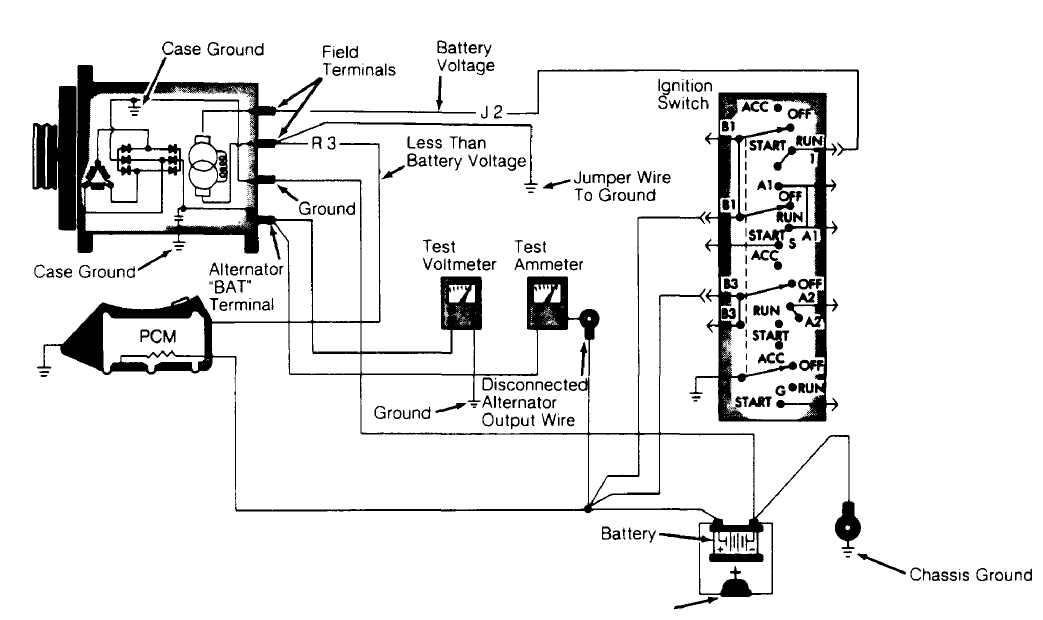
93H76163 Carbon Pile Rheostat
Fig. 3: Testing Alternator Current Output (Typical) Courtesy of Chrysler Corp.
ENTERING ON-BOARD DIAGNOSTICS
CAUTION: Before entering on-board diagnostics, check charging system for other problems. See PRELIMINARY CHECKS under TROUBLE SHOOTING. DO NOT connect DRB-II to vehicle with battery charger connected. Damage to DRB-II may result.
Reading Trouble Codes
Trouble codes may be read by using the CHECK ENGINE light on instrument panel or using DRB-II. See CHECK ENGINE LIGHT DIAGNOSTIC MODE and DIAGNOSIS USING DRB-II headings below. A more complete diagnosis is possible using DRB-II.
NOTE: The PCM CANNOT diagnose every charging system problem. If a fault still exists after performing self-diagnostic procedures, go to TESTING (ON-VEHICLE).
Trouble Code Explanation
See the
CHARGING SYSTEM FAULT CODES table for charging-
related faults.
Code
41 will set if alternator field control
fails to
switch properly. PCM monitors
this circuit whenever ignition is on.
If
battery temperature sense voltage goes out of range,
Code
44 will set in memory. PCM monitors this
circuit any time
ignition is on.
If
battery voltage is more than one volt above desired
control
voltage for longer than 20 seconds, Code
46 will be set in
memory.
PCM monitors this signal whenever engine is running.
If
battery is more than one volt below desired control
voltage
for more than 20 seconds, Code 47
will be set. Code 47 will
also
set if no significant change in voltage is detected
during
alternator test. PCM monitors this signal whenever engine
speed is
more than 1500 RPM.
CHARGING SYSTEM FAULT CODES TABLE
Code Circuit Light Status
41 (1) Alternator Field Control On
44 (1) (2) Battery Temp. Sensor On
(1) High Battery Voltage On
(1) Low Battery Voltage Off
55 End Of Diagnostic Mode Off
- This code will cause limp-in mode.
- Sensor inside PCM. If failed, replace PCM.
NOTE: Only charging system-related codes are listed here. For engine-related codes, see appropriate G - TESTS W/CODES article in the ENGINE PERFORMANCE Section.
CHECK ENGINE Light Diagnostic Mode
Start
engine (if possible). On models equipped
with
automatic transmission, place foot
on brake and cycle transmission
shift
lever through all positions, ending in Park. On all models, turn
A/C
switch on and then off (if equipped).
Turn
engine off. Without starting engine, turn ignition
on,
off, on, off and on. CHECK ENGINE light will come on for 2
seconds
as a bulb
check, followed by fault codes. Record 2-digit fault codes
as
displayed by flashing CHECK ENGINE light.
Once
CHECK ENGINE light begins to flash fault codes, it
cannot be
stopped. Repeat step 1) to enter
diagnostic mode. Code 55
indicates end
of fault code display. For more information on
vehicle
self-diagnostics, see
appropriate SELF-DIAGNOSTICS article in the
ENGINE
PERFORMANCE section.
Refer
to CHARGING SYSTEM FAULT CODES table to relate
trouble
code number to a system fault description (DRB-II display).
Once
trouble area is known, go to appropriate charging system test.
NOTE: CHECK ENGINE light cannot be used to perform actuation test mode, sensor test modes or engine running test. Fault codes can only be erased using DRB-II. Fault codes will be erased from PCM memory after 50 engine starts if fault does not occur again.
Diagnosis Using DRB-II
The DRB-II is used as part of the charging system diagnostic procedure. Perform TEST CH-1, BATTERY CONDITION CHECK and also the CHARGING VERIFICATION (CH-VER) test.
Erasing Fault Codes
To
erase faults, press ATM key. At DRB-ll display, press
"2"
(ERASE) key. DRB-II will display ERASE FAULTS ARE
YOU SURE? (ENTER
TO ERASE).
Press ENTER key.
When
DRB-II is finished erasing fault codes, it will
display FAULTS
ERASED. This display will remain until ATM key is
pressed. After
ATM key is pressed, display will return to CHARGING
MENU screen.
DRB-II TEST FUNCTIONS
NOTE: DO NOT touch DRB-II keypad during DRB-II power-up sequence, or an error message will result.
To
diagnose system with DRB-II, DRB-II must be in CHARGING
MENU. At
CHARGING MENU, fault codes and DRB-II test functions can be
used.
To get to
CHARGING MENU, turn ignition off. Attach DRB-II
to engine
diagnostic connector. Connector is located in engine
compartment,
near PCM. Turn ignition switch to RUN position.
All DRB-II
character positions will glow and copyright
information will
appear on screen for several seconds.
After
several seconds DRB-II menu will appear. At DRB-II
menu,
press "4" (SELECT SYSTEM) key.
Press ENTER key. At SELECT SYSTEM
menu,
press "1" (ENGINE) key. Press
ENTER key. DRB-II menu will
appear, indicating engine year and
size, type of transmission and PCM
part
number.
5) After
several seconds AIR COND menu will appear. Press "1"
(WITH
A/C) or press "2" (WITHOUT A/C).
DRB-II display will change to
ENGINE SYSTEMS menu. At ENGINE SYSTEMS menu, press "2" (CHARGING) key. Press ENTER key.
6) Display
will change to CHARGING MENU. At CHARGING menu of
engine
diagnostic program, specific test functions programmed into
DRB-II
can be performed. Following DRB-II modes can be accessed:
SYSTEM
TEST, READ FAULTS, STATE DISPLAYS, ACTUATOR TEST and
ADJUSTMENTS.
READ FAULTS Mode
This allows technician to read and erase fault codes. Fault counter will appear along with fault displayed on DRB-II. For example, DRB-II will display 1 OF 2 FAULTS. PCM will store up to 8 fault messages.
Faults are numbered in reverse order of setting. Most recent fault to occur will be number one. Vehicles without A/C will always have A/C CLUTCH RELAY CKT (circuit) stored in memory. This fault will always be number one if vehicle is not equipped with A/C. If no fault messages are stored, DRB-II will display NO FAULTS DETECTED and start counter will show 0 STARTS SINCE ERS.
A start counter will appear below DRB-II fault counter display. Start counter counts the number of times vehicle is started since faults were last set, erased or battery was disconnected. This helps determine if fault is intermittent.
Memory space limits start counter to first 3 faults. Start counter of zero equals a hard fault. Start counter of more than zero indicates an intermittent fault. Start counter will count up to 255 starts. If no fault messages are stored, DRB-II will display NO FAULTS DETECTED and start counter will show 0 STARTS SINCE ERS.
STATE DISPLAYS Mode
This allows technician to read status or values of sensors, inputs/outputs and components. PCM can only recognize high and low status on switch circuits. PCM cannot detect the difference between an open or short circuit or a defective switch. If DRB-II displays a change between INPUT HIGH and INPUT LOW, it can be assumed that entire switch circuit to PCM is working.
ACTUATOR TEST Mode
This function allows the technician to check operation of output circuits or devices, which PCM cannot detect. DRB-II allows PCM to activate these outputs or devices. so technician can check for proper operation.
Most tests available in this mode provide an audible or visual indication of device operation (click of relay contacts, fuel spray, etc.). With exception of an intermittent condition, if a device functions properly during its test, it, its wiring and its driver circuit are presumably working properly.
ADJUSTMENTS Mode
This function allows user to erase fault codes. Function also allows user to reset Emission Maintenance Reminder (EMR) light and mileage.
DRB-II Volt/Ohmmeter Mode
To access volt/ohmmeter mode of DRB-II, connect Red
volt/ohmmeter test lead to Red port, located on right-top side of DRB-II .
NOTE: Because DRB-II is grounded through engine diagnostic
connector, only one volt/ohmmeter test is required when using volt/ohmmeter option.
To access voltmeter, press VOLT/OHM key once. DRB-II is now in voltmeter mode. Touch test probe to connector or wire to be measured. Read voltage on DRB-II display. When voltage testing is complete, press VOLT/OHM key 3 times to exit voltmeter mode.
To access ohmmeter, press VOLT/OHM key t,vice. DRB-II is now in ohmmeter mode. Touch test probe to connector or wire to be measured. Read resistance to circuit ground on DRB-II display. When resistance testing is complete, press VOLT/OHM key twice to exit ohmmeter mode.
DRB-II Continuity Meter Mode
Press VOLT/OHM key 3 times. Display will read NO CONTINUITY. Touch test probe to connector or wire to be measured. Read continuity on DRB-II display. When continuity testing is complete, press VOLT/OHM key once to exit continuity meter mode.
VEHICLES TESTED Mode
Mode is used to show what vehicles are covered by DRB-II cartridge. To access VEHICLES TESTED mode, turn ignition off. Attach DRB-II to engine diagnostic connector. Connector is located in engine compartment, near PCM.
Turn ignition switch to RUN position. All DRB-II character positions will glow and copyright information will appear on screen for several seconds. After several seconds DRB-II menu will appear.
At DRB-II menu, press VEHICLES TESTED) key. Press ENTER key. DRB-II will display vehicles covered by cartridge. Screen will display for 5 seconds and return to DRB-II menu.
HOW TO USE Mode
Enter DRB-II menu display. Refer to VEHICLES TESTED MODE. At DRB-II menu, press 2 (HOW TO USE) key. Press ENTER key. A series of screens will be displayed explaining use of DRB-II keys used to move through engine diagnostic program.
TEST CH-1, BATTERY CONDITION CHECK
NOTE: Perform PRELIMINARY CHECKS under TROUBLE SHOOTING before
proceeding. If battery shows signs of freezing or leakage, battery posts are loose or battery has low electrolyte level, DO NOT test.
If
battery has a built-in hydrometer, go to step 2).
Turn
ignition and
all accessories off. Ensure battery voltage is 12.0 volts
or
greater. If voltage is less than 12.0 volts,
charge battery and go
to step 3).
If
battery hydrometer is Green, go to step 3).1f
battery
hydrometer is Yellow or a
bright color, replace battery and perform
CHARGING
VERIFICATION (CH-VER) test. If battery hydrometer is dark in
color,
charge battery and go to next step.
Ensure
battery cables, terminals and posts are clean and
tight. Perform
a battery load test by applying a 300-amp load for 15
seconds.
Wait 15 seconds to allow battery to
stabilize. Apply a load
equal to 50
percent of battery cold cranking rating for 15
seconds and
record
minimum voltage reading.
See
MINIMUM BATTERY VOLTAGE table. If battery is below
volt age,
replace battery and perform CHARGING VERIFICATION (CH-VER)
test.
If voltage reading is okay, go to next step.
MINIMUM BATTERY VOLTAGE TABLE
Battery Temperature Minimum Volts
70F (21C) Or More 9.6
60F (16C) 9.5
50F (1 0C) 9.4
40F (4C) 9.3
30F (-1C) 9.1
20F (-7C) 8.9
1 0F (-1 2C) 8.7
0F (-18C) 8.5
Reconnect
battery cables. Inspect alternator belt tension
and
condition. Replace belt as necessary. Start engine. Set engine
speed
to 2000 RPM for 30 seconds.
Turn ignition off. Connect DRB-II.
Turn ignition on with engine
off. Read faults.
If DRB-II displays BATTERY TEMP SENSOR OUT OF LIMIT,
replace PCM and perform CHARGING VERIFICATION (CH-VER) test. If DRB-II displays other messages, go to appropriate test. If DRB-II does not display any faults, neither fault messages nor faults are intermittent. Go to TEST CH-5, CHECKING FOR INTERMITTENT PROBLEMS.
TEST CH-2, ALTERNATOR FIELD NOT SWITCHING PROPERLY (CODE 41 )
NOTE: Perform TEST CH-1, BATTERY CONDITION CHECK before proceeding.
Put
DRB-II in voltmeter mode. Check voltage of Automatic
Shutdown
(ASD) circuit by probing Dark Green/Orange wire (Dark
Green/Black
wire on Grand Cherokee and Grand Wagoneer) at back of
alternator.
If voltage is less than 10 volts, repair
open circuit from
ignition switch. If voltage is 10 volts
or greater. go to next step.
Check voltage of alternator field driver circuit by
probing Dark Green wire at back of alternator. If voltage is less than 10 volts, go to next step. If voltage is 10 volts or greater, go to step 6).
Turn
ignition off. Disconnect and inspect PCM connector.
Repair,
if necessary. Disconnect alternator harness from back of
alternator.
Using an external ohmmeter, check field driver circuit
(Dark
Green wire) for resistance. If resistance is less than 5.0
ohms,
replace PCM.
If resistance is 5.0 ohms or greater,
repair open in Dark
Green wire.
Turn
ignition off. Disconnect PCM connector. Disconnect
alternator
harness from back of alternator. Using an external
ohmmeter,
check for resistance between alternator field terminals.
If
resistance is 5.0 ohms
or greater, replace alternator. If resistance
is
less than 5.0 ohms, go to next step.
With
DRB-II in ohmmeter mode, check resistance in field
circuit
of alternator harness. If resistance is 5.0 ohms
or greater,
repair short to ground in
field driver circuit (Dark Green wire). If
resistance
is less than 5.0 ohms, replace PCM.
Turn
ignition off. Disconnect PCM connector. Disconnect
alternator
harness from back of alternator. Using an external
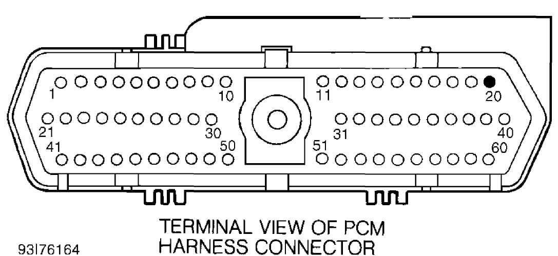
ohmmeter, check for resistance in field driver circuit alternator harness terminal and cavity No. 20 on PCM connector. See Fig. 4. If resistance is 5.0 ohms or greater, repair short to ground in field driver circuit (Dark Green wire). If resistance is less than 5.0 ohms, replace PCM. Perform CHARGING VERIFICATION (CH-VER) test.
JW1
TEST CH-3, CHARGING SYSTEM VOLTAGE LOW (CODE 47)
NOTE:
Perform TEST CH-1, BATTERY CONDITION CHECK before proceeding.
1)1f alternator voltage is 15.1 volts or greater, replace PCM. If less than 15.1 volts, ensure no resistance is present between alternator BAT (B+) and battery positive terminal.
CAUTION: Ensure all wires are clear of moving engine parts.
2) Check alternator case for good continuity to ground and negative battery cable. If continuity is good, manually set engine speed to 1600 RPM. Compare voltage on DRB-II and voltage on an external meter. If voltage difference is one volt or greater, replace the alternator. If the difference is less than one volt, proceed to TEST CH-5, CHECKING FOR INTERMITTENT PROBLEMS.
TEST CH-4, CHARGING SYSTEM VOLTAGE HIGH (CODE 46)
NOTE:
Perform TEST CH-1, BATTERY CONDITION CHECK before proceeding.
Turn
ignition on. Put DRB-II in voltmeter mode. Probe Dark
Green wire
at back of alternator. If voltage is 10.0 volts
or more, go
to step 4).1f voltage is
less than 10.0 volts, turn ignition
off.
Disconnect PCM connector, inspect and repair if necessary.
If
connector is okay, turn ignition on. Probe Dark Green
wire
at back of alternator. If voltage is 10.0 volts
or greater, go to
step 6). If voltage
is less than 10.0 volts, go to next step.
Turn
ignition off. Disconnect alternator harness from
alternator. Put
DRB-II in ohmmeter mode. Probe Dark Green wire in
alternator harness. If resistance is less than 10.0 ohms, repair Dark Green wire for short to ground. If resistance is 10.0 ohms or greater, replace alternator. Perform CHARGING VERIFICATION (CH-VER) test.
4) With ignition on and engine off, read voltage. If less than 13.0 volts, replace PCM. Perform CHARGING VERIFICATION (CH-VER) test. If voltage is 13.0 volts or greater, start engine and read voltage. Compare voltage readings before and after engine is running. Watch for a one-volt difference, waiting up to 5 minutes,.
5)1f voltage difference is one volt or greater, replace PCM. Perform CHARGING VERIFICATION (CH-VER) test. If difference is less than one volt, go to TEST CH-5, CHECKING FOR INTERMITTENT PROBLEMS.
6) Disconnect negative battery cable. Disconnect PCM
connector. Disconnect alternator harness from back of alternator. With DRB-II in ohmmeter mode, check resistance between field driver circuit alternator harness terminal and cavity No. 20 on PCM connector. If resistance is 5.0 ohms or greater, repair short to ground in field driver circuit (Dark Green wire). If resistance is less than 5.0 ohms, go to next step.
7) Probe
one of the alternator field terminals. If resistance
is 5.0
ohms or greater, replace alternator. If resistance
is less than
5.0 ohms, Replace PCM.
Perform CHARGING VERIFICATION (CH-VER) test.
TEST CH-5, CHECKING FOR INTERMITTENT PROBLEMS
NOTE: Perform TEST CH-4, CHARGING SYSTEM VOLTAGE HIGH (CODE 46) before proceeding.
Actuate
alternator field. Put DRB-II in voltmeter mode.
Probe Dark Green
wire at back of alternator. Voltage should cycle from
zero
to battery voltage every 1.4 seconds.
While
watching DRB-II, wiggle wires between alternator and
PCM. If any
interruption in the voltage cycle, repair wire at point at
which
cycle was interrupted. If there is no interruption of voltage
cycle,
test is complete. Perform CHARGING VERIFICATION (CH-VER) test.
CHARGING VERIFICATION (CH-VER)
Ensure
all engine components are connected. If PCM has
been changed and
if vehicle is equipped with a factory theft alarm
system,
start vehicle at least 20 times so alarm
will activate when
desired.
Write
Emission Maintenance Reminder (EMR) mileage into new
PCM. Connect
DRB-II to engine diagnostic connector. and erase faults.
Recheck
system for fault codes.
1f fault
codes reset, charging system still needs repair.
Check all
pertinent TECHNICAL SERVICE BULLETINS, and return to the
TEST
CH-1, BATTERY CONDITION CHECK.
BENCH TESTING
NOTE: Alternators are not serviceable. Replace, if defective.
OVERHAUL
Overhaul information is not available.
TORQUE SPECIFICATIONS
TORQUE SPECIFICATIONS TABLE
Application Ft. Lbs (N.m)
Alternator Mounting Bolts 28 (38)
Idler Pulley (Power Steering) 20 (27)