CRUISE CONTROL SYSTEM
1993 Jeep Cherokee
1993 ACCESSORIES & EQUIPMENT Chrysler Corp. Cruise Control Systems
Jeep: Cherokee, Grand Cherokee, Grand Wagoneer
DESCRIPTION & OPERATION
The cruise control system is electronically controlled and vacuum operated. The electronic control is integrated into the Powertrain Control Module (PCM) located next to the battery. System consists of the following components: PCM, servo, cruise control switch panel, vacuum reservoir, vehicle speed sensor, brakelight switch and Park/Neutral switch (automatic transmission). System controls are located on the steering wheel and consist of ON/OFF, RESUME/ACCEL and SET/DECEL buttons.
SYSTEM CONTROLS
To Set Cruise Control
Press ON/OFF button to turn cruise control system on. Accelerate to desired speed (minimum of 35 MPH) and press SET/DECEL button. Vehicle speed will be maintained.
NOTE: Cruise control system will automatically disengage when
vehicle speed decreases to less than 35 MPH or increases to more than 85 MPH.
To Disengage Cruise Control
Press brake pedal or clutch pedal. The ON/OFF button may also be used, but set speed will be erased from memory. If clutch pedal is used to disengage cruise control, engine speed will increase before cruise control cuts out.
To Resume Previous Speed
If set speed has not been erased from memory and vehicle speed is more than 35 MPH, press RESUME/ACCEL button.
To Increase Speed
With cruise control system on, increase set speed by rapidly pressing and releasing RESUME/ACCEL button. Each pressing of button will cause a speed increase of 2 MPH. For example, 3 presses would result in an increased speed of 6 MPH. To increase speed gradually, hold RESUME/ACCEL button down until desire speed is reached. When button is released, new set speed will be maintained.
To Decrease Speed
With cruise control system on, decrease set speed by pressing SET/DECEL button. Vehicle speed will gradually decrease. Releasing button will set a new speed as long as vehicle speed is still more than 35 MPH.
SELF-DIAGNOSTIC SYSTEM
SYSTEM DIAGNOSTICS
Self-diagnostic capabilities of this system, if properly used, can simplify testing. Cruise control system is monitored by Powertrain Control Module (PCM).
If a problem is sensed with a monitored circuit, a fault code is stored in PCM. Once codes are known, refer to FAULT CODES to determine questionable circuit. Test circuits and repair or replace components as required. If problem is repaired or ceases to exist, PCM cancels that fault code after 50 ignition on/off cycles. To clear codes, refer to CLEARING FAULT CODES.
A specific fault code results from a particular system failure, but is not necessarily reason for failure. Fault code does not condemn a specific component, but calls out a probable malfunction area.
SERVICE PRECAUTIONS
CAUTION: When battery is disconnected, vehicle computer and memory systems may lose memory data. Driveability problems may exist until computer systems have completed a relearn cycle. See COMPUTER RELEARN PROCEDURES article in the GENERAL INFORMATION section before disconnecting battery.
Before proceeding with diagnosis, observe following precautions:
Vehicle must have a fully charged battery and functional
charging system.
Probe PCM 60-pin connector from pin side. DO NOT backprobe
PCM connector.
DO NOT cause short circuits when performing electrical tests.
This will set additional fault codes, making diagnosis of
original problem more difficult.
Always repair lowest fault code number (CHECK ENGINE light)
or first fault displayed (DRB-II) before repairing others.
Always perform TEST SC-VER after repairs are made.
VISUAL INSPECTION
Perform a visual inspection before attempting to diagnose cruise control system problems. A visual inspection may quickly identify cause of a malfunction and eliminate need for diagnostic testing. A thorough visual inspection includes checking for disconnected or faulty wiring harness connectors, leaking or misrouted vacuum hoses, corroded battery terminals or bare wires.
DIAGNOSTIC PROCEDURE
NOTE: When using self-diagnostic tests for diagnosis, DO NOT skip any steps or incorrect diagnosis may result. Always start with TEST SC-1A.
Perform a visual inspection before attempting to diagnose any engine control system problems. Refer to VISUAL INSPECTION. Enter on┬Łboard diagnostics and retrieve all fault codes. Refer to ENTERING ON-BOARD DIAGNOSTICS. If fault codes are NOT present and/or DRB-II (Diagnostic Readout Box II) is used, proceed to TEST SC-1A under SELF-DIAGNOSTIC TESTS.
ENTERING ON-BOARD DIAGNOSTICS
NOTE: Although other scan testers are available, manufacturer recommends using DRB-II (Diagnostic Readout Box II) to diagnose system. CHECK ENGINE light function can be used, but it has limited diagnostic abilities.
NOTE: If fault code exists that is not related to cruise control system, see appropriate G - TESTS W/CODES - 2 . 5L & 4.0L article in the ENGINE PERFORMANCE Section.
CHECK ENGINE Light Diagnostic Mode
With key inserted in ignition switch, cycle ignition
switch to ON position 3 times. On third cycle, leave ignition switch
in ON position. Record 2-digit fault codes as displayed by flashing
CHECK ENGINE light.
For example, Code 34 is displayed as a series of 3 flashes
in rapid succession, followed by a 4-second pause, then 4 flashes in
rapid succession. After a slightly longer pause, other stored codes
are displayed in numerical order.
When CHECK ENGINE light begins to flash fault codes, it
cannot be stopped. If you lose count, it will be necessary to start
over. Code 55 indicates end of fault code display.
Refer to FAULT CODES to translate trouble code number to a
system fault description (DRB-II display). Once trouble area is
identified, refer to TEST SC-1A under SELF-DIAGNOSTIC TESTS to
diagnose problem.
DRB-II Diagnostic Mode
Connect DRB-II to engine diagnostic connector. Connector
is located in engine compartment, near PCM. Turn ignition switch to ON
position. Enter SPEED CONTROL MENU. To enter SPEED CONTROL MENU, see
DRB-II TEST FUNCTIONS.
At SPEED CONTROL MENU, press "2" (READ FAULTS) key. Press
ENTER key. After fault codes are accessed, refer to TEST SC-1A under
SELF-DIAGNOSTIC TESTS to diagnose problem. If no fault codes are
present, see TROUBLE SHOOTING.
To erase fault codes while in this option, press ATM key.
At DRB-II display, press "2" (ERASE) key. DRB-II will display ERASE
FAULTS ARE YOU SURE? (ENTER TO ERASE). Press ENTER key.
When DRB-II is finished erasing fault codes, it will
display FAULTS ERASED. This display will remain until ATM key is
pressed. After ATM key is pressed, display will return to SPEED
CONTROL MENU screen.
CLEARING FAULT CODES
NOTE: Fault codes can also be cleared in READ FAULTS option of
DRB-II. To ensure that all faults are read, it is advisable to use READ FAULTS option to erase fault codes. See DRB-II DIAGNOSTIC MODE under ENTERING ON-BOARD DIAGNOSTICS.
If DRB-II is not available, go to step 3). If DRB-II is
available, enter SPEED CONTROL MENU. See DRB-II TEST FUNCTIONS. At
SPEED CONTROL MENU, press "5" (ADJUSTMENTS) key. Press ENTER key. At
ADJUSTMENTS menu, press "1" (ERASE FAULTS) key. Press ENTER key.
DRB-II will display ERASE FAULTS ARE YOU SURE? (ENTER TO
ERASE). Press ENTER key. When DRB-II is finished erasing fault codes,
screen will display FAULTS ERASED.
If DRB-II is not available, fault codes may be cleared by
disconnecting negative battery cable for at least 15 seconds, allowing
PCM to clear fault codes.
FAULT CODES
FAULT CODES TABLE
Code Display On DRB-II Fault Condition
15 NO VEHICLE SPEED SIGNAL No Vehicle Speed Sensor
" " Signal Detected During
" " Road Load Conditions
34 SPEED CONTROL SOLENOID CIRCUITS .... An Open Or Shorted
" " Condition Detected In Cruise Control
" " Vacuum Or Vent Solenoid Circuits
DRB-II TEST FUNCTIONS
NOTE: For more information on DRB-II test functions, see
appropriate G - TESTS W/CODES - 2.5L & 4.0L article in the ENGINE PERFORMANCE Section.
SPEED CONTROL MENU
To perform cruise control system tests using DRB-II, DRB-
II must be in SPEED CONTROL MENU. At SPEED CONTROL MENU, fault codes
and DRB-II test functions can be accessed.
To reach SPEED CONTROL MENU, turn ignition off. Connect
DRB-II to engine diagnostic connector. Connector is located in engine
compartment, near PCM. Turn ignition switch to RUN position.
NOTE: DO NOT touch DRB-II keypad during DRB-II power-up sequence or an error message will result.
3) All DRB-II character positions will glow and copyright
information will appear on screen for a few seconds. If DRB-II screen
is blank or any error messages appear, see
G - TESTS W/CODES - 2.5L & 4.0L article in the ENGINE PERFORMANCE Section.
4) After a few seconds DRB-II menu will appear. At DRB-II
menu, press "4" (SELECT SYSTEM) key. Press ENTER key. At SELECT SYSTEM
menu, press "1" (ENGINE) key. Press ENTER key. DRB-II menu will appear
indicating engine year, size, type of transmission and PCM part
number.
5) After a few seconds AIR COND menu will appear. Press "1"
(WITH A/C) or press "2" (WITHOUT A/C). DRB-II display will change to
ENGINE SYSTEMS menu. At ENGINE SYSTEMS menu, press "3" (SPEED CONTROL) key. Press ENTER key.
6) Display will change to SPEED CONTROL. At SPEED CONTROL
MENU, specific test functions programmed into DRB-II can be performed.
Following DRB-II modes can be accessed: SYSTEM TESTS, READ FAULTS,
STATE DISPLAY, ACTUATOR TESTS and ADJUSTMENTS.
TROUBLE SHOOTING
* PLEASE READ THIS FIRST *
WARNING: If vehicle is equipped with air bag, air bag must be
deactivated before servicing cruise control components on or around steering column. See AIR BAG RESTRAINT SYSTEM article in the ACCESSORIES/SAFETY EQUIPMENT Section.
NO CRUISE CONTROL WHEN SET BUTTON IS PRESSED & RELEASED
Check for: blown fuse, no vacuum at servo and/or defective servo, disconnected speed control cable, brakelight switch out of adjustment, faulty electrical circuit, faulty Park/Neutral switch input to PCM, faulty PCM.
CRUISE CONTROL ENGAGES WITHOUT ACTUATING CRUISE SET BUTTON
Check for: defective servo, faulty electrical circuit or control switch.
CRUISE CONTROL ENGAGES WHEN ENGINE IS STARTED
Check for: defective servo, faulty electrical circuit. ERRATIC SPEED OR ENGINE SHUTS OFF
Check for: poor engine performance (surge), defective vehicle speed sensor, vacuum leak, faulty servo, faulty PCM.
CRUISE CONTROL DISENGAGES ON ROUGH ROAD
Check for: brakelight switch out of adjustment, faulty electrical circuit.
ENGINE DOES NOT RETURN TO NORMAL IDLE
Check for: kinked and/or damaged cruise control cable, faulty throttle linkage.
NO RESUME WHEN RESUME BUTTON IS PRESSED
Check for: defective switch, faulty electrical circuit. CRUISE CONTROL DOES NOT DISENGAGE WITH BRAKE PEDAL DEPRESSED
Check for: defective or improperly adjusted brakelight switch, kinked and/or damaged speed control cable, faulty electrical circuit.
TESTING (WITHOUT DRB-II)
Brakelight Switch
Disconnect brakelight switch 6-pin connector. Using an ohmmeter, check for continuity at switch side of connector terminals. See the TESTING BRAKELIGHT SWITCH table. If continuity is not as specified, check brakelight switch adjustment. If switch adjustment is okay, replace defective brakelight switch.
TESTING BRAKELIGHT SWITCH TABLE
Pedal Position/Test Terminals Continuity
Released
1 & 4 Yes
3 & 6 Yes
2 & 5 No
Depressed
1 & 4 No
3 & 6 No
2 & 5 Yes
NOTE: For connector terminal identification, refer to the CONNECTOR IDENTIFICATION table. For appropriate wiring diagram, see appropriate chassis wiring diagram in the WIRING DIAGRAMS section.
CRUISE CONTROL CIRCUIT
Disconnect Powertrain Control Module (PCM) connector. On
XJ models, PCM is located on drivers side fender. On ZJ models, PCM is
located on passenger side firewall. Using external voltmeter, connect
negative lead to vehicle ground.
Turn ignition on. Check voltage at terminal No. 33.
Voltage should be zero volts with cruise control switch in OFF
position. Voltage should be battery voltage with switch in ON
position. Repair harness as necessary if voltage is not correct.
Check voltage at terminal No. 53. Voltage should be zero
volts with cruise control switch in OFF position. Voltage should be
battery voltage with switch in ON position. Repair harness as
necessary if voltage is not correct.
Check voltage at terminal No. 48. Voltage should be zero
volts with cruise control switch off. Voltage should be battery
voltage with switch on. With switch in ON position, voltage should
drop to zero volts when SET button is pressed. Repair harness as
necessary if voltage is not correct.
Check voltage at terminal No. 50. Voltage should be zero
volts with cruise control switch in ON or OFF position. With cruise
control switch in SET or RESUME position, voltage should be battery
voltage. Repair harness as necessary if voltage is not correct.
Check voltage at terminal No. 49. Voltage should be zero
volts with cruise control switch off. Voltage should be battery
voltage with switch on. With cruise control switch in SET or RESUME
position, voltage should be battery voltage. Repair harness as
necessary if voltage is not correct.
Using external ohmmeter, check resistance between terminal
No. 29 of PCM connector and vehicle ground. Pressing brake pedal,
ohmmeter should display continuity with pedal released. With brake
pedal depressed, ohmmeter should display open circuit.
CRUISE CONTROL SERVO TEST
Turn ignition on. Place cruise control switch in ON
position. Using external voltmeter, connect negative lead to vehicle
ground. Disconnect servo connector. Check voltage at pin No. 2 (Dark
Blue/Red wire) of servo connector. If voltage is less than battery
voltage, check for loose connections, brake switch adjustment or
damaged harness.
Connect a jumper wire between terminal No. 2 (Dark
Blue/Red wire) of servo connector and corresponding terminal of servo. Check voltage at 3 remaining male servo terminals. If voltage is less than battery voltage at each terminal, replace servo.
3) Using external ohmmeter, measure resistance between
terminal No. 1 of servo connector and vehicle ground. If resistance is more than 5 ohms, check and repair harness as needed.
CRUISE CONTROL SWITCH - ZJ MODELS
Access cruise control switch. See Fig. 10. Disconnect cruise control switch 4-pin connector. Using an ohmmeter, check cruise control switch. If cruise control switch does not test as specified, replace switch. See TESTING CRUISE CONTROL SWITCH table.
NOTE: Testing of cruise control switch without DRB-II on XJ models is not provided by manufacturer.
TESTING CRUISE CONTROL SWITCH TABLE
Switch Position Check Between Pin Nos. Ohms
OFF 3 & 4 5890-6510
OFF 1 & 3 (1) *
ON 1 & 4 5890-6510
ON 1 & 3 (2) *
ON/SET 3 & 4 1020-1130
ON/RESUME 3 & 4 2040-2260
- No continuity should exist.
- Continuity should exist.
SERVO VACUUM
Remove cruise control cable from throttle body. Disconnect
cruise control servo 4-pin connector. Disconnect vacuum hose at cruise
control servo. Apply battery voltage to terminal No. 2 (Dark Blue/Red
wire) of servo connector. Using jumper wire, ground remaining 3
terminals of servo connector.
Connect hand held vacuum pump to servo vacuum nipple, and
apply 10-15 in. Hg of vacuum. Cruise control cable should retract and
maintain position as long as vacuum is applied. If servo does not test
as specified, replace servo.
VACUUM SUPPLY
Disconnect vacuum hose at cruise control servo. Install
vacuum gauge to disconnected vacuum hose. Start engine and observe
gauge. Vacuum reading should be a minimum of 10 in. Hg. Turn engine
off. Vacuum should continue to hold at a minimum of 10 in. Hg.
If vacuum is not as specified, check for kinked or leaking
vacuum lines, defective check valve, defective vacuum reservoir and/or
poor engine performance. If no problems are found, check cruise
control servo. See CRUISE CONTROL SERVO TEST.
REMOVAL & INSTALLATION
* PLEASE READ THIS FIRST *
WARNING: If vehicle is equipped with air bag, air bag must be
deactivated before servicing cruise control components on or around steering column. See AIR BAG RESTRAINT SYSTEM article in the ACCESSORIES/SAFETY EQUIPMENT Section.
CRUISE CONTROL SERVO
Removal
Remove cruise control cable mounting bracket from servo. Remove servo mounting bracket. Disconnect wiring harness connector and vacuum hose from servo. Pull cable away from servo to expose retaining clip. Remove retaining clip and cable. Remove servo.
Installation
With throttle in full open position, align hole in cruise control cable sleeve with hole in servo pin. Install retaining clip. To complete installation, reverse removal procedure.
CRUISE CONTROL SWITCH
Removal & Installation (XJ Models)
1) Disconnect negative battery cable. Remove horn button by
turning while pushing. Remove horn bushing, receiver and flexplate. Turn ignition switch to LOCK position and remove steering wheel nut with washer. Scribe alignment mark on steering wheel and steering shaft.
Remove vibration damper from steering column hub (if
equipped). Remove steering wheel. Using appropriate compressor, remove
lockplate snap ring and lockplate. Remove canceling cam and upper
bearing preload spring. Remove horn button components from canceling
cam.
Remove hazard warning switch knob. Remove actuator arm
attaching screw. Remove turn signal switch attaching screws. Unplug
cruise control switch connector. Pull cruise control harness out of
column. Turn ignition switch to ON position. Remove key warning buzzer
switch and retainer.
Remove ignition lock cylinder retaining screw and pull out
lock cylinder. Remove housing and shroud assembly. Ensure dimmer
switch rod, lock pin or lock rack do not fall out of assembly. Pull
turn signal/wiper lever straight out of column.
Remove wiper switch cover from back of housing and shroud
assembly. Remove pivot screw from housing and remove switch. Install
NEW switch and cover. Push on dimmer switch rod and position housing
and shroud to column.
Ensure nylon spring retainer on lock pin is positioned
forward of retaining slot of lock rack. Position first tooth of gear
with forward tooth of lock rack.
Secure housing and shroud assembly. Insert key and lock
cylinder. Ensure lock pin extends fully when key is moved to lock
position. To install remaining components, reverse disassembly
procedure. Tighten steering wheel nut to 25 ft. lbs. (34 N.m).
Removal & Installation (ZJ Models)
Turn ignition switch to OFF position. Remove 2 screws from back of steering wheel. Rock switch back and forth to remove switch from steering wheel. Disconnect cruise control switch connector. To install switch, reverse removal procedure.
CONNECTOR IDENTIFICATION
CONNECTOR IDENTIFICATION TABLE
Connector Go To Figure:
Brakelight Switch See Fig. 1
Clockspring Assembly See Fig. 2
Cruise Control Servo See Fig. 3
Cruise Control Switch (XJ Model) See Fig. 4
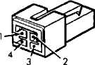
Cruise Control Switch (ZJ Model) See Fig. 5
Fuse Block See Fig. 6
Powertrain Control Module (PCM) See Fig. 7
Vehicle Speed Sensor See Fig. 8
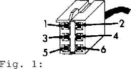
Identifying Brakelight Switch Connector Terminals Courtesy of Chrysler Corp.
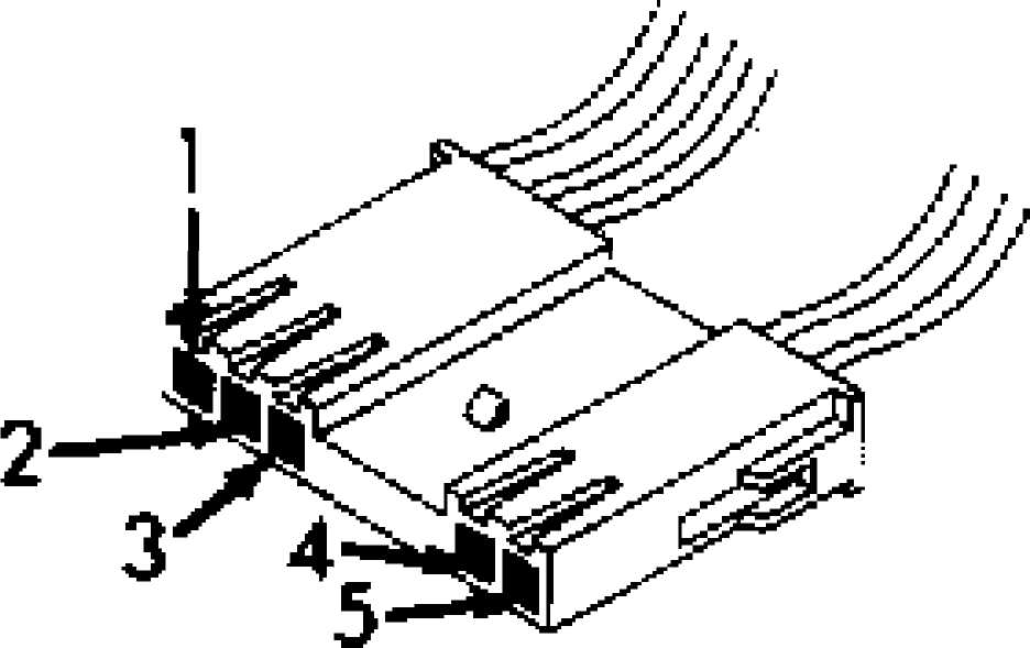
Fig. 2: Identifying Clockspring Connector Terminals Courtesy of Chrysler Corp.
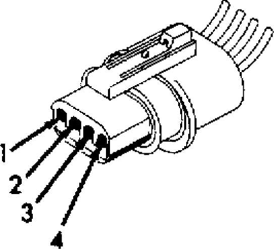
Fig. 3: Identifying Cruise Control Servo Connector Terminals Courtesy of Chrysler Corp.
93176081
Fig. 4: Cruise Control Switch Connector Terminal ID (XJ Model) Courtesy of Chrysler Corp.
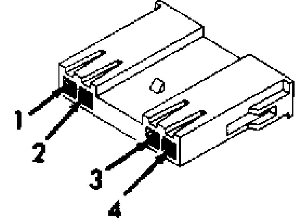
Fig. 5: Cruise Control Switch Connector Terminal ID (ZJ Model) Courtesy of Chrysler Corp.
 Speed Control Fuse
POWER DISTRIBUTION CENTER XJ MODELS
93J76082
Fig. 6: Identifying Power Distribution Center (XJ Models) Courtesy of Chrysler Corp.
 7
7
Speed Control Fuse
FUSE BLOCK ZJ MODELS
93A76083
Fig. 7: Identifying Fuse Block (ZJ Models) Courtesy of Chrysler Corp.
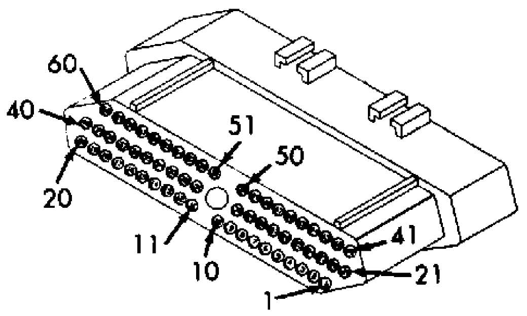
Fig. 8: Powertrain Control Module (PCM) Connector Terminal ID Courtesy of Chrysler Corp.
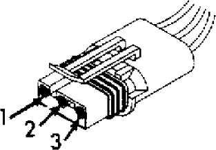
Fig. 9: Identifying Vehicle Speed Sensor Connector Terminals Courtesy of Chrysler Corp.
SELF-DIAGNOSTICS
* PLEASE READ THIS FIRST *
WARNING: If vehicle is equipped with air bag, air bag must be
deactivated before servicing cruise control components on or around steering column.
CAUTION: Always turn ignition switch to OFF position before disconnecting or connecting any module connector.
NOTE: In following self-diagnostic tests, illustrations are courtesy of Chrysler Corp. For connector terminal identification, see CONNECTOR IDENTIFICATION. For appropriate wiring diagrams, see WIRING DIAGRAM.
TEST SC-1A - CHECKING FOR CRUISE CONTROL SYSTEM FAULTS
NOTE: For connector terminal identification, refer to
the CONNECTOR IDENTIFICATION table. For appropriate wiring diagram, see appropriate chassis wiring diagram in the WIRING DIAGRAMS section.
Ensure battery is fully charged. With engine off, turn
ignition switch to ON position. Using DRB-II, read fault messages.
If the DRB-II displays SPEED CONTROL SOLENOID CIRCUIT,
proceed to TEST SC-2A. If DRB-II displays NO VEHICLE SPEED SENSOR
SIGNAL, go to TEST SC-3A. If DRB-II does not display any fault
messages, proceed to TEST SC-4A.
TEST SC-2A - REPAIRING POWER & GROUND SUPPLY FOR OPEN TO
SERVO SOLENOIDS
NOTE: For connector terminal identification, refer to
the CONNECTOR IDENTIFICATION table. For appropriate wiring diagram, see appropriate chassis wiring diagram in the WIRING DIAGRAMS section.
While listening to cruise control servo, cycle cruise
control ON/OFF switch. If cruise control servo clicks when cycling
ON/OFF switch, go to TEST SC-2B. If cruise control servo does not
click when cycling ON/OFF switch, disconnect cruise control servo
connector. Inspect connector and clean and repair as needed.
Place cruise control ON/OFF switch in ON position. Ensure
brake pedal is not depressed during following step. Using DRB-II in
voltmeter mode, check cruise control solenoid feed voltage at terminal
No. 2 (Dark Blue/Red wire) of cruise control servo connector.
If voltage is more than 10 volts, check ground circuit
resistance at cruise control servo connector terminal No. 1 (Black
wire) using DRB-II in ohmmeter mode. If resistance is less than 5
ohms, replace speed control servo. Perform TEST SC-VER. If resistance
is more than 5 ohms, repair open system ground (Black) wire to cruise
control servo. Perform TEST SC-VER.
If cruise control solenoid feed voltage is less than 10
volts, backprobe (with connector connected) brake switch connector at
terminal No. 4, (Dark Blue/Red wire on XJ, Dark Blue/Light Blue wire
on ZJ) of solenoid feed circuit. Ensure brake pedal is not depressed.
DO NOT disconnect brake switch connector. If voltage is more than 10
volts, repair open in Dark Blue/Red wire between cruise control servo
and brake switch. Perform TEST SC-VER.
If voltage is less than 10 volts, backprobe (with
connector connected) ON/OFF switch sense circuit at brake switch
connector terminal No. 5 (Yellow/Red wire) using DRB-II. If voltage is
more than 10 volts, adjust or replace brake switch as necessary.
Perform TEST SC-VER. If voltage is less than 10 volts, repair open cruise control ON/OFF switch sense circuit (Yellow/Red wire) on XJ models.
On ZJ models, remove steering column covers to gain access
to cruise control switch connector. Using DRB-II in voltmeter mode,
backprobe (with connector connected) ON/OFF switch sense circuit at
cruise control switch connector terminal No. 3 (White wire). If
voltage is less than 10 volts, replace cruise control switch. Perform
TEST SC-VER.
If voltage is more than 10 volts, backprobe (with
connector connected) ignition 12-volt feed circuit at clockspring
connector terminal No. 2 (Yellow/Red wire) using DRB-II. See Fig. 10.
DO NOT disconnect clockspring connector.
If voltage is less than 10 volts, replace clockspring
assembly. See Fig. 10. Perform TEST SC-VER. If voltage is more than 10
volts, repair open cruise control ON/OFF switch sense circuit
(Yellow/Red wire) between the clockspring and the brake switch. Perform TEST SC-VER.
Cruise Control Switch Connector
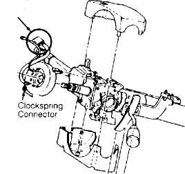
93E75931 Fig. 10: Identifying Clockspring Assembly Location
TEST SC-2B - CRUISE CONTROL VACUUM SOLENOID CONTROL CIRCUIT
NOTE: For connector terminal identification, refer to
the CONNECTOR IDENTIFICATION table. For appropriate wiring diagram, see appropriate chassis wiring diagram in the WIRING DIAGRAMS section.
1) Turn ignition switch to OFF position. Disconnect
Powertrain Control Module (PCM) connector. Inspect connector and clean and repair as needed. Turn ignition switch to ON position.
Place cruise control ON/OFF switch in ON position. Using
DRB-II in voltmeter mode, check vacuum solenoid control circuit
voltage at PCM connector terminal No. 33 (Tan/Red wire). If voltage is
more than 10 volts, go to TEST SC-2C. If voltage is less than 10
volts, disconnect cruise control servo connector. Inspect connector
and clean and repair as needed.
Using DRB-II in ohmmeter mode, check vacuum solenoid
control circuit resistance at cruise control servo connector terminal
No. 4 (Tan/Red wire). If resistance is less than 5 ohms, repair short
to ground in Tan/Red wire. Perform TEST SC-VER.
If resistance is more than 5 ohms, check resistance
between terminal No. 33 of PCM connector and terminal No. 4 of cruise
control servo connector using external ohmmeter. Both have Tan/Red
wire.
If resistance is less than 5 ohms, replace cruise control
servo. Perform TEST SC-VER. If resistance is more than 5 ohms, repair
open cruise control vacuum solenoid control (Tan/Red wire) circuit.
Perform TEST SC-VER.
TEST SC-2C - CRUISE CONTROL VENT SOLENOID CONTROL CIRCUIT
NOTE: For connector terminal identification, refer to
the CONNECTOR IDENTIFICATION table. For appropriate wiring diagram, see appropriate chassis wiring diagram in the WIRING DIAGRAMS section.
Using DRB-II in voltmeter mode, check vent solenoid
control circuit voltage at terminal No. 53 (Light Green/Red wire) of
Powertrain Control Module (PCM). If voltage is more than 10 volts,
replace PCM. Perform TEST SC-VER. If voltage is less than 10 volts,
disconnect cruise control servo connector. Inspect connector and clean
and repair as needed.
Using DRB-II in ohmmeter mode, check vent solenoid control
circuit resistance at cruise control servo connector terminal No. 3
(Light Green/Red wire). If resistance is less than 5 ohms, repair
short to ground in Light Green/Red wire. Perform TEST SC-VER.
If resistance is more than 5 ohms, check vent solenoid
control circuit resistance between PCM connector terminal No. 53
(Light Green/Red wire) and cruise control servo connector terminal No.
3 using an external ohmmeter. If resistance is less than 5 ohms,
replace cruise control servo. Perform TEST SC-VER. If resistance is
more than 5 ohms, repair open in the Light Green/Red wire. Perform
TEST SC-VER.
TEST SC-3A - NO VEHICLE SPEED SENSOR SIGNAL
NOTE: For connector terminal identification, refer to
the CONNECTOR IDENTIFICATION table. For appropriate wiring diagram, see appropriate chassis wiring diagram in the WIRING DIAGRAMS section.
Raise and support vehicle. Start engine. Using DRB-II,
read Vehicle Speed Sensor (VSS) signal. Shift transmission into any
forward gear. If DRB-II does not display more than zero MPH, check if
vehicle is equipped with electronic automatic transmission (EATX). If
vehicle is equipped with electronic automatic transmission, go to
TEST SC-3B.
If vehicle is not equipped with electronic automatic
transmission, inspect quantity of wires attached to speed sensor
connector. If speed sensor has 3 wire connector, go to TEST SC-3C. If
speed sensor has 2 wire connector, go to TEST SC-3E.
If DRB-II displays more than zero MPH in 1), the condition
required to set fault is not present at this time. The vehicle speed
sensor signal fault sets if PCM does not see a VSS signal at PCM
terminal No. 47 (White/Orange wire) for 11 seconds under road load
conditions. Possible causes are open or shorted VSS signal circuit
(White/Orange wire), failed VSS or open VSS 8-volt feed circuit
(Orange wire) (without electronic automatic transmission), or failed
Transmission Control Module (TCM) (with electronic automatic
transmission).
Inspect all related wiring and connectors and repair as
necessary. If no problems were found with wiring and connectors, see
INACTIVE FAULT CONDITION in the G - TESTS W/CODES - 2.5L & 4.0L
article in the ENGINE PERFORMANCE Section. Perform TEST SC-VER. If it
was necessary to repair related wiring and connectors, perform TEST
SC-VER.
TEST SC-3B - NO VEHICLE SPEED SENSOR SIGNAL
NOTE: For connector terminal identification, refer to
the CONNECTOR IDENTIFICATION table. For appropriate wiring diagram, see appropriate chassis wiring diagram
in the WIRING DIAGRAMS section.
Using DRB-II, read electronic automatic transmission fault
codes. If fault code(s) 50-58 is displayed, go to appropriate article
in the TRANSMISSION SERVICE section. If fault code(s) 50-58 is not
displayed, turn ignition switch to OFF position.
Disconnect Transmission Control Module (TCM) connector.
Inspect connector and clean and repair as needed. Turn ignition switch
to ON position. Using DRB-II in voltmeter mode, check Vehicle Speed
Sensor (VSS) signal circuit at terminal No. 58 (White/Orange wire) of
TCM connector.
If voltage is more than 4 volts, go to step 5). If voltage
is less than 4 volts, turn ignition switch to OFF position. Disconnect
PCM connector. Inspect connector and clean and repair as needed. Using
an external ohmmeter, check VSS signal circuit resistance between
terminal No. 58 (White/Orange wire) of TCM connector and PCM connector
terminal No. 47.
If resistance is more than 5 ohms, repair open in
White/Orange wire. Perform TEST SC-VER. If resistance is less than 5 ohms, place DRB-II in ohmmeter mode. Using DRB-II in ohmmeter mode, check VSS signal circuit resistance at PCM connector terminal No. 47 (White/Orange wire). If resistance is more than 5 ohms, replace PCM.
Perform TEST SC-VER. If resistance is less than 5 ohms, repair short to ground in White/Orange wire. Perform TEST SC-VER.
Connect a jumper wire to TCM connector terminal No. 58,
VSS signal circuit (White/Orange wire). Using DRB-II, monitor vehicle
speed while tapping open end of jumper wire to ground. If DRB-II
displays vehicle speed more than zero MPH, replace the TCM. Perform
TEST SC-VER. If DRB-II does not display vehicle speed more than zero
MPH, turn ignition switch to OFF position.
Disconnect and inspect PCM connector. Inspect connector
and clean and repair as needed. Using external ohmmeter, check
resistance of VSS signal circuit (White/Orange wire) between TCM
connector terminal No. 58 and PCM connector terminal No. 47.
If resistance is less than 5 ohms, replace PCM. Perform
TEST SC-VER. If resistance is more than 5 ohms, repair open in
White/Orange wire. Perform TEST SC-VER.
TEST SC-3C - NO VEHICLE SPEED SENSOR SIGNAL
NOTE: For connector terminal identification, refer to
the CONNECTOR IDENTIFICATION table. For appropriate wiring diagram, see appropriate chassis wiring diagram in the WIRING DIAGRAMS section.
Turn ignition switch to OFF position. Disconnect Vehicle
Speed Sensor (VSS) connector. Inspect connector and clean and repair
as needed. Turn ignition switch to ON position.
Using DRB-II in voltmeter mode, check 8-volt feed circuit
voltage at terminal No. 3 (Orange wire) of VSS connector. If voltage
is less than 7 volts, repair open in Orange wire. Perform TEST SC-VER.
If voltage is more than 7 volts, check VSS signal circuit
voltage at terminal No. 1 (White/Orange wire) of VSS connector using
DRB-II. If voltage is less than 4 volts, go to TEST SC-3D. If voltage
is more than 4 volts, connect a jumper wire to VSS connector terminal
No. 1 (White/Orange wire).
Using DRB-II, monitor vehicle speed while tapping open end
of jumper wire to VSS ground circuit, connector terminal No. 2
(Black/Light Blue wire). If DRB-II displays vehicle speed more than
zero MPH, replace VSS. Perform TEST SC-VER. If DRB-II does not display
vehicle speed more than zero MPH, turn ignition switch to OFF
position.
Using DRB-II in ohmmeter mode, check VSS ground circuit
resistance at terminal No. 2 (Black/Light Blue wire) of VSS connector. If resistance is more than 5 ohms, repair open in Black/Light Blue wire to harness splice. Perform TEST SC-VER. If resistance is less than 5 ohms, turn ignition switch to OFF position.
Disconnect PCM connector. Inspect connector and clean and
repair as needed. Using external ohmmeter, check VSS signal circuit
resistance at PCM connector terminal No. 47 (White/Orange wire).
If resistance is less than 5 ohms, replace PCM. Perform
TEST SC-VER. If resistance is more than 5 ohms, repair open in
White/Orange wire. Perform TEST SC-VER.
TEST SC-3D - NO VEHICLE SPEED SENSOR SIGNAL
NOTE: For connector terminal identification, refer to
the CONNECTOR IDENTIFICATION table. For appropriate wiring diagram, see appropriate chassis wiring diagram in the WIRING DIAGRAMS section.
Turn ignition switch to OFF position. Disconnect PCM
connector. Inspect connector and clean and repair as needed. Using
DRB-II in ohmmeter mode, check Vehicle Speed Sensor (VSS) signal
circuit resistance at PCM connector terminal No. 47, (White/Orange
wire). If resistance is less than 5 ohms, repair short to ground in
White/Orange wire. Perform TEST SC-VER.
If resistance is more than 5 ohms, check resistance of VSS
signal circuit (White/Orange wire) between PCM connector terminal No.
47 and VSS connector terminal No. 1 using an external ohmmeter.
If resistance is less than 5 ohms, replace PCM. Perform
TEST SC-VER. If resistance is more than 5 ohms, repair open in
White/Orange wire. Perform TEST SC-VER.
TEST SC-3E - NO VEHICLE SPEED SENSOR SIGNAL
NOTE: For connector terminal identification, refer to
the CONNECTOR IDENTIFICATION table. For appropriate wiring diagram, see appropriate chassis wiring diagram in the WIRING DIAGRAMS section.
Ensure ignition is off. Disconnect VSS connector. Inspect
connector and clean and repair as needed. Turn ignition on. Using DRB-
II in voltmeter mode, check VSS signal at VSS connector terminal No. 1
(White/Orange wire). If voltage is less than 4 volts, go to TEST SC-
3F.
If voltage is more than 4 volts, connect a jumper wire to
VSS connector terminal No. 2 (Black/Light Blue wire). While observing
DRB-II, tap open end of jumper wire on terminal No. 1 of VSS
connector. If DRB-II displays more than zero MPH, replace VSS. Perform
TEST SC-VER.
If DRB-II displays zero MPH readings, turn ignition off.
Using DRB-II, check VSS ground circuit at terminal No. 2 (Black/Light
Blue wire) of VSS connector. If resistance is greater than 5 ohms,
repair sensor ground wire for open circuit to harness splice. If
resistance is less than 5 ohms, go to TEST SC-3G.
TEST SC-3F - NO VEHICLE SPEED SENSOR SIGNAL
NOTE: For connector terminal identification, refer to
the CONNECTOR IDENTIFICATION table. For appropriate wiring diagram, see appropriate chassis wiring diagram in the WIRING DIAGRAMS section.
1) Turn ignition off. Disconnect PCM connector. Inspect connector and clean and repair as needed. Using DRB-II in ohmmeter
mode, measure VSS signal resistance at terminal No. 47 (White/Orange wire) of PCM connector. If resistance is less than 5 ohms, repair VSS signal circuit for short to ground. Perform TEST SC-VER.
2) If resistance is more than 5 ohms, measure resistance between terminal No. 47 (White/Orange wire) of PCM connector and terminal No. 1 of VSS connector using external ohmmeter. If resistance is more than 5 ohms, repair open VSS signal wire. Perform TEST SC-VER. If resistance is less than 5 ohms, replace the PCM module. Perform TEST SC-VER.
TEST SC-3G - NO VEHICLE SPEED SENSOR SIGNAL
NOTE: For connector terminal identification, refer to
the CONNECTOR IDENTIFICATION table. For appropriate wiring diagram, see appropriate chassis wiring diagram in the WIRING DIAGRAMS section.
Turn ignition off. Disconnect PCM connector. Inspect
connector and clean and repair as needed. Using external ohmmeter,
check VSS signal resistance between terminal No. 47 (White/Orange
wire) of PCM connector and terminal No. 1 of VSS connector.
If resistance is more than 5 ohms, repair open speed
sensor signal wire. Perform TEST SC-VER. If resistance is less than 5
ohms, replace PCM module. Perform TEST SC-VER.
TEST SC-4A - CHECKING CRUISE CONTROL SWITCHES
NOTE: For connector terminal identification, refer to
the CONNECTOR IDENTIFICATION table. For appropriate wiring diagram, see appropriate chassis wiring diagram in the WIRING DIAGRAMS section.
Using DRB-II, read cruise control inputs monitor. While
watching cruise control ON/OFF input, cycle cruise control ON/OFF
switch several times. If DRB-II display does not correspond with
switch position, go to TEST SC-5A.
If DRB-II display does correspond with switch position,
place cruise control ON/OFF switch in ON position. While watching
RESUME input, cycle resume switch several times. If DRB-II display
does not correspond with switch position, go to TEST SC-6A.
If DRB-II display does correspond with switch position,
cycle SET switch several times while watching SET switch input. If
DRB-II display does not correspond with switch position, proceed to
TEST SC-7A. If DRB-II display does correspond with switch position,
depress and release brake pedal several times while watching BRAKE
pedal input.
If DRB-II display does not correspond with brake pedal
position, go to TEST SC-10A. If DRB-II display does correspond with
brake pedal position, check if vehicle is equipped with a manual
transmission. If vehicle is equipped with manual transmission, go to
TEST SC-11A.
If vehicle is not equipped with manual transmission,
ensure ignition switch is in ON position. While watching P/N SWITCH
input, cycle gear selector several times between "P", "R", "N" and
"D". If DRB-II display does not correspond with selector position, go
to TEST SC-12A. If DRB-II display does correspond with selector
position, go to TEST SC-11A.
TEST SC-5A - CHECKING CRUISE CONTROL ON/OFF SWITCH SENSE CKT
NOTE: For connector terminal identification, refer to
the CONNECTOR IDENTIFICATION table. For appropriate wiring diagram, see appropriate chassis wiring diagram
in the WIRING DIAGRAMS section.
Using DRB-II in voltmeter mode, check voltage at both
sides of cruise control fuse. If voltage input side of fuse (Dark Blue
wire) is less than 10 volts, repair open in Dark Blue wire to cruise
control fuse. Perform TEST SC-VER.
If voltage input side of fuse (Dark Blue wire) is more
than 10 volts, inspect speed control fuse. If fuse is good, go to step
4). If fuse is open (NG), disconnect cruise control switch connector.
Inspect connector and clean and repair as needed. Using DRB-II in
ohmmeter mode, check ignition 12-volt feed at cruise control switch
connector terminal No. 2 (Dark Blue/White wire) on ZJ models, terminal
No. 4 (Dark Blue/White wire) on XJ models.
If resistance is less than 5 ohms, go to TEST SC-5C. If
resistance is more than 5 ohms, turn ignition off. On all models,
disconnect PCM module. Inspect connector and clean and repair as
needed. Go to TEST SC-5B.
Backprobe (with connector connected) ignition 12-volt feed
circuit at cruise control switch connector terminal No. 2 (Dark
Blue/White wire) on ZJ models, terminal No. 4 (Dark Blue/White wire)
on XJ models using DRB-II in voltmeter mode.
If voltage is less than 10 volts, go to TEST SC-5D. If
voltage is more than 10 volts, push cruise control switch to ON
position. On all models, backprobe (with connector connected) cruise
control ON/OFF switch sense circuit voltage at terminal No. 1
(Yellow/Red wire) of cruise control switch connector.
If voltage is less than 10 volts, replace cruise control
switch. Perform TEST SC-VER. If voltage is more than 10 volts, turn
ignition off. Disconnect PCM connector. Inspect connector and clean
and repair as needed. Turn ignition on. Ensure cruise control is still
in ON position.
Using DRB-II in voltmeter mode, check cruise control
ON/OFF switch voltage at terminal No. 49 (Yellow/Red wire) of PCM
connector. If voltage reads less than 10 volts, repair open in the
cruise control ON/OFF switch sense wire to the PCM connector. Perform
TEST SC-VER. If voltage reads more than 10 volts, replace the PCM
module. Perform TEST SC-VER.
TEST SC-5B - REPAIRING A SHORT IN SPEED CONTROL SWITCH CKTS
NOTE: For connector terminal identification, refer to
the CONNECTOR IDENTIFICATION table. For appropriate wiring diagram, see appropriate chassis wiring diagram in the WIRING DIAGRAMS section.
Using DRB-II in ohmmeter mode, check cruise control set
switch resistance at terminal No. 48 (Brown/Red wire) of PCM module.
If resistance is less than 5 ohms, repair cruise control set switch
sense circuit short to ground. Perform TEST SC-VER.
If resistance is more than 5 ohms, check cruise control
resume sense circuit resistance at terminal No. 50 (White/Light Green
wire) of PCM module using DRB-II in ohmmeter mode. If resistance is
less than 5 ohms, repair cruise control resume switch sense circuit
short to ground. Replace cruise control fuse. Perform TEST SC-VER.
If resistance is more than 5 ohms, check cruise control
ON/OFF switch sense resistance at terminal No. 49 (Yellow/Red wire) of
PCM connector using DRB-II in ohmmeter mode. If resistance is more
than 5 ohms, replace PCM module. Replace cruise control fuse. Perform
TEST SC-VER.
If resistance is less than 5 ohms, disconnect brake switch
connector. Inspect connector and clean and repair as needed. Check
cruise control ON/OFF switch sense resistance at terminal No. 49
(Yellow/Red wire) of PCM module connector. If resistance is less than
5 ohms, repair cruise control ON/OFF switch sense circuit short to ground. Replace cruise control fuse. Perform TEST SC-VER.
If resistance is more than 5 ohms, check cruise control
ON/OFF switch sense resistance at terminal No. 1 (Yellow/Red wire) of
brake switch connector output. If resistance is more than 5 ohms,
replace brake switch. Replace cruise control fuse. Perform TEST SC-
VER.
If resistance is less than 5 ohms, disconnect cruise
control servo connector. Using DRB-II in ohmmeter mode, check cruise
control ON/OFF switch sense circuit resistance at terminal No. 2 of
servo connector.
If resistance is more than 5 ohms, replace cruise control
servo. Replace cruise control fuse. Perform TEST SC-VER. If resistance
is less than 5 ohms, repair cruise control ON/OFF switch sense circuit
short to ground. Replace cruise control fuse. Perform TEST SC-VER.
TEST SC-5C - REPAIRING SHORT IN IGNITION 12 VOLT FEED CIRCUIT
NOTE: For connector terminal identification, refer to
the CONNECTOR IDENTIFICATION table. For appropriate wiring diagram, see appropriate chassis wiring diagram in the WIRING DIAGRAMS section.
On XJ models, repair ignition 12-volt feed circuit to
cruise control switch for a short to ground. Replace cruise control
fuse. Perform TEST SC-VER. On ZJ models, disconnect clockspring
connector. See Fig. 10 in TEST SC-2A. Using DRB-II in ohmmeter mode,
check ignition 12-volt feed circuit at terminal No. 3 (White/Red wire)
of clockspring connector.
If resistance is below 5 ohms, repair ignition 12-volt
feed circuit short to ground. Replace cruise control fuse. Perform
TEST SC-VER. If resistance is more than 5 ohms, replace clockspring
assembly. Replace cruise control fuse. Perform TEST SC-VER.
TEST SC-5D - REPAIRING OPEN IN IGNITION 12 VOLT FEED CIRCUIT
NOTE: For connector terminal identification, refer to
the CONNECTOR IDENTIFICATION table. For appropriate wiring diagram, see appropriate chassis wiring diagram in the WIRING DIAGRAMS section.
On XJ models, repair open 12-volt feed fuse to cruise
control switch circuit. Perform TEST SC-VER. On ZJ models, disconnect
clockspring connector. See Fig. 10 in TEST SC-2A. Using DRB-II in
voltmeter mode, check ignition 12-volt feed circuit voltage at
terminal No. 3 (White/Red wire) of clockspring connector.
If voltage is more than 10 volts, replace clockspring
assembly. Perform TEST SC-VER. If voltage is less than 10 volts,
repair open ignition 12-volt feed clockspring to fuse block circuit.
Perform TEST SC-VER.
TEST SC-6A - REPAIRING CRUISE CONTROL RESUME SWITCH SENSE CKT
NOTE: For connector terminal identification, refer to
the CONNECTOR IDENTIFICATION table. For appropriate wiring diagram, see appropriate chassis wiring diagram in the WIRING DIAGRAMS section.
1) Turn ignition switch to OFF position. Disconnect PCM module connector. Inspect connector and clean and repair as needed. Turn ignition on. Using DRB-II in voltmeter mode, check cruise control resume sense circuit voltage at terminal No. 1 (White/Light Green wire) of PCM module connector.
If voltage is more than 10 volts, replace cruise control
switch. Perform TEST SC-VER. If voltage is less than 10 volts,
determine if vehicle is XJ or ZJ model. If vehicle is XJ model, go to
step 6). If vehicle is ZJ model, backprobe (with connector connected)
resume switch sense circuit voltage at terminal No. 3 (White wire) of
cruise control switch connector.
Hold down resume switch button. If voltage is less than 10
volts, replace cruise control switch. Perform TEST SC-VER. Release
resume switch button. If voltage is more than 10 volts, backprobe
(with connector connected) cruise control resume switch sense circuit
voltage at terminal No. 2 (White/Light Green wire) of output side of clockspring connector using DRB-II in voltmeter mode. See Fig. 10 in TEST SC-2A.
Hold down resume switch button. If voltage is less than 10
volts, replace clockspring assembly. Perform TEST SC-VER. Release
resume switch button. Check cruise control resume sense circuit
voltage at terminal No. 50 (White/Light Green wire) of PCM module
connector. Hold down resume switch button.
If voltage is less than 10 volts, repair open cruise
control resume sense circuit between clockspring and PCM module.
Perform TEST SC-VER. If voltage is more than 10 volts, replace PCM
module. Perform TEST SC-VER.
6) On XJ models, backprobe (with connector connected) cruise control resume switch sense circuit voltage at terminal No. 2 (White/Light Green wire) of cruise control switch connector using DRB-II in voltmeter mode. Hold down resume switch button. If voltage is less than 10 volts, replace cruise control switch. If voltage is more than 10 volts, release resume switch button.
7) Check cruise control resume sense circuit voltage at
terminal No. 50 (White/Light Green wire) of PCM module connector. Hold down resume switch button. If voltage is less than 10 volts, repair open cruise control resume switch sense circuit between switch and PCM module. Perform TEST SC-VER. If voltage is more than 10 volts, replace PCM module. Perform TEST SC-VER.
TEST SC-7A - REPAIRING CRUISE CONTROL SET SWITCH CIRCUIT
NOTE: For connector terminal identification, refer to
the CONNECTOR IDENTIFICATION table. For appropriate wiring diagram, see appropriate chassis wiring diagram in the WIRING DIAGRAMS section.
1) Turn ignition switch to OFF position. On XJ models go to
step 6).On ZJ models, disconnect PCM module. Inspect connector and
clean and repair as needed. Turn ignition on. Ensure cruise control
switch is in ON position. Using DRB-II in voltmeter mode, backprobe
(with connector connected) cruise control set switch sense circuit
voltage at terminal No. 4 (Brown/Red wire) of switch connector.
If voltage is less than 10 volts, replace cruise control
switch. Perform TEST SC-VER. If voltage is more than 10 volts,
backprobe (with connector connected) cruise control set switch sense
circuit at terminal No. 4 (Brown/Red wire) of clockspring connector
using DRB-II in voltmeter mode. See Fig. 10 in TEST SC-2A.
If voltage is less than 10 volts, replace clockspring
assembly. Perform TEST SC-VER. If voltage is more than 10 volts, check
cruise control set switch sense circuit voltage at terminal No. 48
(Brown/Red wire) of PCM connector.
If voltage is less than 10 volts, repair open cruise
control set switch sense circuit between switch and PCM. If voltage is
more than 10 volts, hold set switch in ON position.
Check cruise control set switch sense circuit voltage at
terminal No. 48 (Brown/Red wire) of PCM connector. If voltage is more
than 10 volts, replace cruise control switch. Perform TEST SC-VER. If
voltage measures less than 10 volts, replace the PCM module. Perform TEST SC-VER.
Disconnect PCM module. Inspect connector and clean and
repair as needed. Turn ignition on. Using DRB-II in voltmeter mode,
check cruise control set switch sense circuit voltage at terminal No.
48 (Brown/Red wire) of PCM connector. If voltage is more than 10
volts, replace cruise control switch. Perform TEST SC-VER.
If voltage is less than 10 volts, hold set switch button
in ON position. Backprobe (with connector connected) cruise control
set switch sense circuit voltage at terminal No. 3 (Brown/Red wire) of
cruise control switch connector. If voltage is less than 10 volts,
replace cruise control switch. Perform TEST SC-VER.
If voltage is more than 10 volts, check cruise control set
switch sense circuit voltage at terminal No. 48 (Brown/Red wire) of
PCM connector. Continue to hold down set switch button. If voltage is
less than 10 volts, repair open cruise control set switch sense
circuit between switch and PCM. Perform TEST SC-VER. If voltage is
more than 10 volts, replace PCM module. Perform TEST SC-VER.
TEST SC-8A - CHECKING CRUISE CONTROL SWITCH CIRCUIT
NOTE: For connector terminal identification, refer to
the CONNECTOR IDENTIFICATION table. For appropriate wiring diagram, see appropriate chassis wiring diagram in the WIRING DIAGRAMS section.
Inspect cruise control fuse. If fuse is okay, go to step
4). If fuse is open (NG), disconnect cruise control switch connector.
Inspect connector and clean and repair as needed. Using DRB-II in
ohmmeter mode, check cruise control ON/OFF switch sense circuit
resistance at terminal No. 3 (White wire) of switch connector.
If resistance is more than 5 ohms, go to TEST SC-9A. If
resistance is less than 5 ohms, disconnect clockspring. See Fig. 10 in
TEST SC-2A. Inspect connector and clean and repair as needed. Using
DRB-II in ohmmeter mode, check ignition 12-volt feed circuit
resistance at terminal No. 5 (White/Red wire) of clockspring
connector.
If resistance is more than 5 ohms, replace clockspring.
Perform TEST SC-VER. Replace cruise control fuse. If resistance is
less than 5 ohms, repair short to ground in White/Red wire. Perform
TEST SC-VER. Replace cruise control fuse.
Using DRB-II in voltmeter mode, backprobe (with connector
connected) ignition 12-volt feed circuit at terminal No. 1 (Yellow/Red
wire) of cruise control switch connector. If voltage is more than 10
volts, go to step 6). If voltage is less than 10 volts, using DRB-II,
backprobe (with connector connected) ignition 12-volt feed circuit at
terminal No. 5 (White/Red wire) at clockspring connector.
If voltage is more than 10 volts, replace clockspring. See
Fig. 10 in TEST SC-2A. Perform TEST SC-VER. If voltage is less than 10
volts, repair open in the White/Red wire to the fuse panel. Perform
TEST SC-VER.
Turn ignition switch to OFF position. Disconnect PCM
connector. Perform TEST SC-VER. Turn ignition switch to ON position.
Place cruise control ON/OFF switch in ON position. Using DRB-II in
voltmeter mode, backprobe (with connector connected) cruise control
mode select sense circuit voltage at No. 4 (Brown/Red wire) of switch
connector.
If voltage is less than 10 volts, go to TEST SC-8B. If
voltage is more than 10 volts, check cruise control mode select sense
circuit voltage at terminal No. 23 (Red/Light Green wire) at PCM
connector. If voltage is less than 10 volts, go to TEST SC-8C.
If voltage is more than 10 volts, disconnect cruise
control switch connector. Using external ohmmeter, check resistance
between cruise control switch connector terminal No. 1 (Yellow/Red wire) and terminal No. 4 (Brown/Red wire). If resistance is 5890-6510 ohms, replace PCM. Perform TEST SC-VER. If resistance is not 5890-6510 ohms, replace cruise control switch. Perform TEST SC-VER.
TEST SC-8B - TESTING CLOCKSPRING CIRCUIT FOR SHORTS
NOTE: For connector terminal identification, refer to
the CONNECTOR IDENTIFICATION table. For appropriate wiring diagram, see appropriate chassis wiring diagram in the WIRING DIAGRAMS section.
1) Disconnect cruise control switch connector. Inspect
connector and clean and repair as needed. Using DRB-II in ohmmeter
mode, check mode select sense circuit resistance at terminal No. 23
(Red/Light Green wire) of PCM connector.
If resistance is more than 5 ohms, replace cruise control
switch. Perform TEST SC-VER. If resistance is less than 5 ohms,
disconnect clockspring connector. See Fig. 10 in TEST SC-2A. Inspect
connector and clean and repair as needed.
Using DRB-II, check mode select sense circuit (Red/Light
Green wire) resistance at terminal No. 23 (Red/Light Green wire) of
PCM connector. If resistance is more than 5 ohms, replace clockspring
assembly. Perform TEST SC-VER. If resistance is less than 5 ohms,
repair short to ground in Red/Light Green wire. Perform TEST SC-VER.
TEST SC-8C - TESTING CLOCKSPRING CIRCUIT FOR OPEN
NOTE: For connector terminal identification, refer to
the CONNECTOR IDENTIFICATION table. For appropriate wiring diagram, see appropriate chassis wiring diagram in the WIRING DIAGRAMS section.
Using DRB-II, backprobe (with connector connected) mode select sense circuit at terminal No. 4 (Red/Light Green wire)of clockspring connector. See Fig. 10 in TEST SC-2A. If voltage is less than 10 volts, replace clockspring assembly. Perform TEST SC-VER. If voltage is more than 10 volts, repair open in Red/Light Green wire. Perform TEST SC-VER.
TEST SC-9A - REPAIRING CRUISE CONTROL SWITCH CKT SHORT TO GND
NOTE: For connector terminal identification, refer to
the CONNECTOR IDENTIFICATION table. For appropriate wiring diagram, see appropriate chassis wiring diagram in the WIRING DIAGRAMS section.
1) Disconnect cruise control servo connector. Inspect
connector and clean and repair as needed. Using DRB-II in ohmmeter
mode, check on/off switch sense circuit resistance at terminal No. 1
(Yellow/Red wire) of switch connector on ZJ models. On XJ models, check resistance at terminal No. 3 (White wire) of switch connector.
On all models, if resistance is more than 5 ohms, replace
cruise control servo. Replace cruise control fuse. Perform TEST SC-
VER. If resistance is less than 5 ohms, disconnect brake switch
connector. Inspect connector and clean and repair as needed.
Using DRB-II in ohmmeter mode, check on/off switch sense
circuit resistance at terminal No. 1 (Yellow/Red wire) of switch
connector on ZJ models. On XJ models, check resistance at terminal No.
3 (White wire) of switch connector. On all models, if resistance is
less than 5 ohms, go to step 5). If resistance is more than 5 ohms,
check cruise control ON/OFF switch sense circuit resistance at
terminal No. 1 (Yellow/Red wire) of brake switch connector.
If resistance is less than 5 ohms, repair ON/OFF switch
sense circuit for short to ground between brake switch and servo.
Replace cruise control fuse. Perform TEST SC-VER. If resistance is
more than 5 ohms, replace brake switch. Replace cruise control fuse.
Perform TEST SC-VER.
Disconnect clockspring connector. See Fig. 10 in TEST SC-
2A. Inspect connector and clean and repair as needed. Using DRB-II in
ohmmeter mode, check cruise control ON/OFF switch sense circuit
resistance at terminal No. 1 (Yellow/Red wire) of brake switch
connector input.
If resistance is more than 5 ohms, replace clockspring
assembly. Replace cruise control fuse. Perform TEST SC-VER. If
resistance is less than 5 ohms, repair ON/OFF switch sense circuit for
short to ground. Perform TEST SC-VER.
TEST SC-10A - CHECKING BRAKE SWITCH CIRCUIT FOR OPEN
NOTE: For connector terminal identification, refer to
the CONNECTOR IDENTIFICATION table. For appropriate wiring diagram, see appropriate chassis wiring diagram in the WIRING DIAGRAMS section.
If DRB-II displays RELEASED at all times, go to TEST SC-
10B. If DRB-II does not display RELEASED at all times, disconnect
brake switch. Inspect connector and clean and repair as needed.
Connect a jumper wire between terminal No. 3 (White/Pink
wire on XJ, Brown wire on ZJ) and terminal No. 6 (Black wire). Using
DRB-II, read cruise control inputs monitor. If DRB-II does not display
RELEASED, go to step 4).
If DRB-II displays RELEASED, check brake switch
adjustment. If brake switch is adjusted correctly, replace brake
switch. Perform TEST SC-VER. If brake switch is not adjusted
correctly, adjust brake switch. Perform TEST SC-VER.
Connect jumper wire between brake switch connector
terminal No. 3 and ground. Using DRB-II, read cruise control inputs
monitor. If DRB-II displays RELEASED, repair open in Black wire to
brake switch. If DRB-II does not display RELEASED, turn ignition
switch to OFF position. Remove jumper wire. Disconnect PCM connector.
Inspect connector and clean and repair as needed.
Check brake switch sense circuit resistance between
terminal No. 3 (White/Pink wire on XJ, Brown wire on ZJ) of brake
switch connector and terminal No. 29 of PCM connector using an
external ohmmeter.
If resistance is more than 5 ohms, repair open White/Pink
or Brown wire between brake switch and PCM. Perform TEST SC-VER. If
resistance is less than 5 ohms, replace PCM. Perform TEST SC-VER.
TEST SC-10B - CHECKING BRAKE SWITCH CIRCUIT FOR SHORTS
NOTE: For connector terminal identification, refer to
the CONNECTOR IDENTIFICATION table. For appropriate wiring diagram, see appropriate chassis wiring diagram in the WIRING DIAGRAMS section.
Disconnect brake switch connector. Inspect connector and
clean and repair as needed. Using DRB-II, read cruise control inputs
monitor. If DRB-II displays PRESSED, go to step 3). If DRB-II does not
display PRESSED, turn ignition switch to OFF position. Disconnect PCM
connector. Inspect connector and clean and repair as needed. Using
DRB-II in ohmmeter mode, check brake switch sense circuit resistance
at terminal No. 29 (White/Pink on XJ, Brown wire on ZJ) of PCM
connector.
If resistance is less than 5 ohms, repair short to ground
in White/Pink or Brown wire between the brake switch and the PCM. Perform TEST SC-VER. If resistance is more than 5 ohms, replace PCM. Perform TEST SC-VER.
3) Check brake switch adjustment. If brake switch is adjusted correctly, replace brake switch. Perform TEST SC-VER. If brake switch is not adjusted correctly, adjust brake switch. Perform TEST SC-VER.
TEST SC-11A - CHECKING CRUISE CONTROL SERVO OPERATION
NOTE: For connector terminal identification, refer to
the CONNECTOR IDENTIFICATION table. For appropriate wiring diagram, see appropriate chassis wiring diagram in the WIRING DIAGRAMS section.
Disconnect cruise control servo connector. Inspect
connector and clean and repair as needed. Using DRB-II in ohmmeter
mode, check ground circuit resistance at terminal No. 1 (Black wire)
of cruise control servo connector.
If resistance is more than 5 ohms, repair open Black wire
to cruise control servo. Perform TEST SC-VER. If resistance is less
than 5 ohms, connect cruise control servo connector. Check if vehicle
is equipped with a vacuum reservoir. If vehicle is equipped with
vacuum reservoir, go to TEST SC-11B.
If vehicle is not equipped with a vacuum reservoir,
disconnect cruise control servo vacuum hose. Connect vacuum gauge to
servo vacuum hose. Start engine. If gauge does not read at least 10
in. Hg of vacuum, repair vacuum leak or restriction between servo and
vacuum source. Perform TEST SC-VER.
If gauge reads at least 10 in. Hg of vacuum, turn engine
off. Turn ignition switch to ON position. Press cruise control ON/OFF
switch to ON position. Using an alternative source of constant vacuum
feed, connect vacuum feed to servo. Using DRB-II, actuate servo
solenoids. If throttle fully opens and closes, go to TEST SC-13A.
If throttle does not fully open and close, stop actuation
test. Inspect cruise control servo cable condition. If cruise control
servo cable is okay, replace cruise control servo. Perform TEST SC-
VER. If cruise control servo cable is not okay, repair or adjust cable
as necessary. Perform TEST SC-VER.
TEST SC-11B - CHECKING VACUUM TO CRUISE CONTROL SERVO
NOTE: For connector terminal identification, refer to
the CONNECTOR IDENTIFICATION table. For appropriate wiring diagram, see appropriate chassis wiring diagram in the WIRING DIAGRAMS section.
Start engine. Turn engine off. Turn ignition switch to ON
position. Using DRB-II, actuate servo solenoids. If throttle fully
opens and closes, go to TEST SC-13A. If throttle does not fully open
and close, stop actuation test.
Disconnect vacuum hose at cruise control servo. Using an
alternative source of constant vacuum feed, connect vacuum feed to
servo. Using DRB-II, actuate servo solenoids. If throttle fully opens
and closes, repair vacuum leak or restriction between servo and vacuum
source. Perform TEST SC-VER.
If throttle does not fully open and close, stop actuation
test. Inspect cruise control servo cable. If cruise control servo
cable is okay, replace cruise control servo. Perform TEST SC-VER. If
cruise control servo cable is not okay, repair or adjust cable as
necessary. Perform TEST SC-VER.
TEST SC-12A - CHECKING PARK/NEUTRAL SWITCH CIRCUIT
NOTE: For connector terminal identification, refer to
the CONNECTOR IDENTIFICATION table. For appropriate wiring diagram, see appropriate chassis wiring diagram in the WIRING DIAGRAMS section.
Disconnect Park/Neutral switch connector at transmission.
Inspect connector and clean and repair as needed. Using DRB-II, read
cruise control inputs monitor.
If DRB-II displays D/R, replace Park/Neutral switch.
Perform TEST SC-VER. If DRB-II does not display D/R, turn ignition
switch to OFF position. Disconnect PCM connector. Inspect connector
and clean and repair as needed.
Using DRB-II in ohmmeter mode, check park/neutral switch
sense circuit resistance at terminal No. 30 (Brown/Yellow wire on XJ,
Brown/White wire on ZJ) of PCM connector. If resistance is less than 5
ohms, repair short to ground in wire. Perform TEST SC-VER. If
resistance is more than 5 ohms, replace PCM. Perform TEST SC-VER.
TEST SC-13A - CHECKING FOR INTERMITTENT FAULTS
NOTE: For connector terminal identification, refer to
the CONNECTOR IDENTIFICATION table. For appropriate wiring diagram, see appropriate chassis wiring diagram in the WIRING DIAGRAMS section.
Reconnect and reassemble all previously tested components.
Connect DRB-II to engine diagnostic connector so DRB-II display can be
seen from driverÆs seat. Road test vehicle. Using DRB-II, read CUTOUT
monitor on DRB-II display. If DRB-II display shows erratic vehicle
speed, replace vehicle speed sensor. Perform TEST SC-VER.
If DRB-II does not display erratic vehicle speed, Place
cruise control ON/OFF switch in ON position. With vehicle speed at a
minimum of 35 MPH, press and release cruise control SET/DECEL switch.
If DRB-II displays S/C ALLOWED and cruise control is inoperative,
repair cruise control servo vacuum feed or mechanical problems as
necessary. Perform TEST SC-VER. If DRB-II displays S/C ALLOWED and
cruise control is operative, perform following:
Check for cruise control disengagement without driver command
by driving vehicle under various road conditions.
If cruise control disengages without driver command, using
DRB-II, read CUTOUT monitor S/C DENIED message. See
appropriate DENIED MESSAGE in DRB-II INTERMITTENT FAULT
MESSAGES table and correct problem as necessary. Perform TEST
SC-VER.
If cruise control does not disengage without driver command,
using DRB-II, read CUTOUT monitor. Compare GOAL value with
SPEED value. If values are not within 2 MPH of each other,
replace PCM. Perform TEST SC-VER. If values are within 2 MPH
of each other, test is complete.
3) If DRB-II displays S/C DENIED, see appropriate DENIED
MESSAGE in DRB-II INTERMITTENT FAULT MESSAGES table and correct
problem as necessary.
DRB-II INTERMITTENT FAULT MESSAGES TABLE
Denied Message Problem To Correct
BRAKE Open Circuit At PCM Terminal No. 2 9
CLUTCH RPM/Vehicle Speed Ratio Is Not Constant
ON/OFF Lack Of Voltage At PCM Terminal No. 23
P/N Open Circuit At PCM Terminal No. 30
RPM/SPD RPM/Vehicle Speed Ratio Is Not Constant
SPEED Vehicle Speed As Read By Vehicle
" Speed Sensor Is Less Than 35 MPH
RPM Engine RPM Is Excessively High
SOL/FLT Fault In Servo Vent Or Vacuum Solenoid
" Circuit That Is Either Maturing Or Set
TEST SC-VER - CRUISE CONTROL VERIFICATION
Reconnect and reassemble all previously tested components. If PCM has been changed, and vehicle is equipped with factory theft alarm, start vehicle at least 20 times so alarm system may be activated when desired. Connect DRB-II to engine diagnostic connector and erase faults. To ensure no other fault remains, perform following:
Road test vehicle at a speed above 35 MPH. Place cruise
control ON/OFF switch in the ON position. Press and release the
SET/DECEL switch. If cruise control does not engage, repair is not
complete. Check all related TECHNICAL SERVICE BULLETINS and return to
TEST SC-1A as necessary.
Press and release RESUME/ACCEL switch. If vehicle speed
does not increase by 2 MPH, repair is not complete. Check all related
TECHNICAL SERVICE BULLETINS and return to TEST SC-1A as necessary.
Depress and release brake pedal. If cruise control does
not disengage, repair is not complete. Check all related TECHNICAL
SERVICE BULLETINS and return to TEST SC-1A as necessary.
Increase vehicle speed to 35 MPH. Press RESUME/ACCEL
switch. If cruise control does not resume previously set speed, repair
is not complete. Check all related TECHNICAL SERVICE BULLETINS and
return to TEST SC-1A, as necessary.
Hold down SET/DECEL switch. If vehicle does not
decelerate, repair is not complete. Check all related TECHNICAL
SERVICE BULLETINS and return to TEST SC-1A as necessary.
Ensure vehicle speed is greater than 35 MPH and release
SET/DECEL switch. If vehicle does not adjust to new vehicle speed,
repair is not complete. Check all related TECHNICAL SERVICE BULLETINS
and return to TEST SC-1A as necessary.
Place ON/OFF switch in OFF position. If cruise control
does not disengage, repair is not complete. Check all related
TECHNICAL SERVICE BULLETINS and return to TEST SC-1A as necessary.
If vehicle successfully passed all previous tests, cruise
control system is now functioning correctly. Repair is complete.
WIRING DIAGRAM
For wiring diagram, see appropriate chassis wiring diagram article in the WIRING DIAGRAMS section.