Ā
1993 Jeep Cherokee
1993 Drive Axles
7 1/8", 7 9/16" & 8 1/4" Ring Gears
Cherokee, Grand Cherokee, Grand Wagoneer, Wrangler
DESCRIPTION
Front and rear drive axle assemblies have hypoid type gears with integral carrier housings. See Fig. 1. Model 30 front axle is used on all models. Model 35 rear axle is standard on all models. Cherokee models without ABS are available with optional rear axle with 8 1/4" ring gear.
Optional limited slip differentials are available. Model 35 and 44 axles use Trac-Lok limited slip system. Trac-Lok is serviceable if repair is needed. The 8 1/4" differential is available with Sure-Grip limited slip system. Sure-Grip must be replaced as an assembly if repair is necessary.
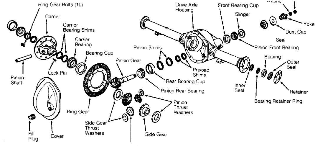
Pinion Gear
Fig. 1: Exploded View Of Rear Axle Assembly (Typical) Courtesy of Chrysler Corp.
IDENTIFICATION
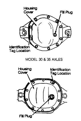
Axle build date and manufacturer number are stamped on
passenger-side axle tube near housing cover. See Fig. 2. Axle assembly part number, gear ratio and identification tag is attached to housing cover bolts. See AXLE RATIO & IDENTIFICATION table.
Model 35 axle shaft tubes are 2.625" (66.67 mm) in diameter. 8 1/4" axle shaft tubes are 3.0" (76.2 mm) in diameter.
AXLE RATIO & IDENTIFICATION TABLE
Axle Ratio
Pinion/Ring Gear Tooth Combinations
Ring Gear Diameter
Front Axle (1) 3.07:1 .... 3.55:1 4.10:1
Rear Axle 3.07:1 (2) 3.55:1 (2) 3.55:1 (3) 4.10:1 (2) 4.10:1 (3)
14/43 7 1/8" (181 mm)
11/39 7 1/8" (181 mm)
9/37 7 1/8" (181 mm)
14/43 7 9/16" (192 mm)
11/39 7 9/16" (192 mm)
11/39 8 1/4" (209 mm)
9/37 7 9/16" (192 mm)
41/10 8 1/4" (209 mm)
- Model 30 axle used on all models.
- Model 35 axle used on all models.
- Optional rear axle for Cherokee only.
8 1/41 AXLE
93D75922
Fig. 2: Locating Drive Axle Identification Tag Courtesy of Chrysler Corp.
REMOVAL & INSTALLATION
REAR AXLE SHAFT, BEARING, SEALS & RETAINER
NOTE: To service front axle shaft, bearings, seals and retainer,
see FRONT AXLES article.
Removal
Raise and support vehicle. Remove rear wheel(s). Remove
brake drum. Clean axle housing cover. Loosen cover bolts and drain
oil. Remove cover.
Remove differential pinion-shaft lock screw or spring
clips. Remove pinion shaft from differential. Push axle in. Remove "C"
clip from axle at pinion gear. Remove axle from tube. Remove axle
shaft seal and bearing from axle tube.
Installation
Grease bearing and install in axle tube. Apply wheel
bearing grease to axle shaft seal. Install seal in axle tube. Install
axle shaft.
Install axle "C" clip. Pull axle out to seat "C" clip.
Install pinion shaft. Install lock screw, and tighten to
specification. Install pinion shaft spring clips (if equipped). Apply RTV to axle housing cover. Tighten cover bolts to specification. See TORQUE SPECIFICATIONS table. Fill with gear oil.
NOTE: On vehicles with Trac-Lok (limited slip) differentials, slowly drive vehicle in 10-12 "figure 8" patterns to distribute lubricant to clutch and bearing assembly.
PINION SEAL & YOKE
Removal
Raise and support vehicle. Remove wheels and brake
rotor/drums. Stamp or paint a reference mark at rear drive shaft to
axle yoke. Disconnect and remove drive shaft. Rotate yoke 3 or 4
times.
Measure amount of torque needed (in INCH lbs.) to rotate
pinion gear. Record torque reading for installation procedure. Remove
pinion nut and discard. DO NOT reuse nut.
Index mark yoke-to-pinion position for installation. Using
Puller(C-452) and Yoke Support Wrench (C-3281), remove pinion yoke.
Remove pinion seal, and wipe surface of seal bore clean.
Installation
1) Coat pinion seal with axle oil and install. Align and
install yoke on pinion shaft. Install NEW pinion nut and tighten only
enough to remove end play. DO NOT tighten pinion nut further yet.
CAUTION: DO NOT overtighten or loosen and retighten pinion nut. If required preload torque is exceeded, replace collapsible pinion spacer and reset pinion preload.
2) Place an INCH-lb. torque wrench on pinion nut. Rotate
pinion and note rotating torque. Hold yoke with Yoke Support Wrench
(C-3281) . Tighten pinion nut until preload torque is same as amount recorded during removal, plus 5 INCH lbs. (.56 N.m). Pinion nut torque should equal or exceed torque specification. See TORQUE SPECIFICATIONS table.
3) Align and install drive shaft. Tighten "U" joint clamp
bolts. Install brake drum/rotors and wheels. Tighten lug nuts to
specification. See TORQUE SPECIFICATIONS table. Check oil level.
DRIVE AXLE HOUSING
Removal
Raise and support vehicle on frame rails. Remove wheels.
Index mark drive shaft and axle yoke for installation reference.
Remove drive shaft.
Disconnect rear track bar (if equipped) at axle bracket.
Remove axle vent tube at axle. Disconnect parking brake cables at
equalizer (rear axle). Remove shock absorbers. Disconnect brake
hose(s) .
On all except Wrangler, support axle housing. Disconnect
upper and lower control arms at axle. Lower and remove assembly to
release coil spring pressure. Remove coil springs. Lower and remove
axle housing assembly from vehicle.
On Wrangler, loosen, but DO NOT remove, bolts attaching
spring eyes to frame brackets and shackles. Support axle housing.
Remove spring "U" bolts and tie plates. Raise axle housing just enough
to relieve weight from springs.
Remove bolts attaching springs to frame bracket and
shackles. Lower springs to floor. Lower jack slowly, and remove axle
housing assembly from vehicle.
Installation
Align spring mounting points, and place axle in position. To install, reverse removal procedure.
DIFFERENTIAL CARRIER & PINION
Removal (Except Cherokee 8 1/4" Ring Gear)
Raise and support vehicle. Remove axle housing cover and
drain oil. Index mark drive axle and drive shaft yokes for
installation. Remove drive shaft.
Remove wheels, brake rotor/drums and axle shafts. Mount
Housing Spreader (W-129-A) on axle housing. Mount dial indicator.
Spread housing enough to remove differential carrier. See Fig. 3.
CAUTION: DO NOT spread housing more than .015" (.38 mm) or damage to housing may result.
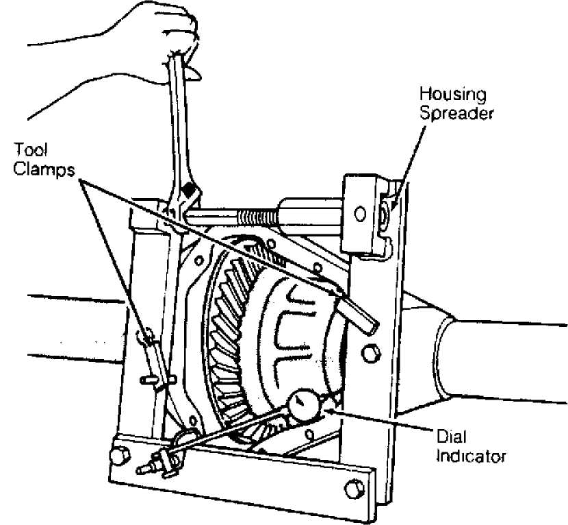
Fig. 3: Spreading Housing To Remove Differential Carrier Courtesy of Chrysler Corp.
3) Index mark bearing caps for installation reference. Loosen bearing caps until almost out. Pry differential carrier loose. Remove
bearing caps. Remove differential carrier. Remove housing spreader. Check the pinion preload and remove the pinion gear assembly. See PINION SEAL & YOKE.
Installation (Except Cherokee 8 1/4" Ring Gear)
1) Install pinion gear, pinion bearings and seal (if
removed). Adjust pinion preload. See REASSEMBLY under OVERHAUL. Spread housing as during removal.
Place differential carrier with bearing races and shims in
axle housing. Using a mallet, tap outer edges of drive axle bearing
races to seat differential carrier. Remove housing spreader.
Install bearing caps. Tighten bolts to specification. See
TORQUE SPECIFICATIONS table. Check and adjust ring gear backlash and
tooth contact. If pinion gear, bearings or seal was serviced, adjust
pinion preload.
Apply 1/4" (6.35 mm) bead of RTV sealant to axle housing
cover. Install cover. Tighten cover bolts to specification. Connect
drive shaft. Fill axle with 2.5 pts. (1.2L) 75W-90 gear oil.
NOTE: For differentials with Trac-Lok or Sure-Grip, add friction modifier (limited slip additive).
Removal (Cherokee 8 1/4" Ring Gear)
Raise and support vehicle. Remove wheels and brake drums.
Mark drive shaft for reassembly. Remove drive shaft. Drain oil and
remove housing cover. Remove pinion shaft lock screw. Remove pinion
shaft.
Push axle shafts in and remove "C" clips. Remove axles.
Measure and record differential side play, ring gear runout and pinion
gear preload.
Mark differential gear and carrier at point of maximum
runout. Side play should not exist. If ring gear runout exceeds .005"
(.13 mm), replace differential carrier.
Remove pinion yoke and seal. Mark side bearing caps and
axle housing for reassembly. Remove adjuster locks. Loosen, but DO NOT
remove, bearing caps. Insert Hex Adjuster (C-4164) through axle tube
and loosen hex adjuster on each side.
Remove bearing caps, adjusters and differential carrier.
Keep all bearing races, bearings and adjusters together. Using brass
drift, hammer pinion shaft out of housing.
Drive bearing races out of housing. Remove shim(s) from
behind rear races, and record thickness. Remove bearing from pinion
shaft using Bearing Puller (C-293-PA) and Bearing Remover Adapter(C-
293-42).
Mount differential carrier in soft-jawed vise. Remove and
discard ring gear bolts (LEFT-HAND thread). Using soft-faced hammer,
drive ring gear off differential carrier.
Installation (Cherokee 8 1/4" Ring Gear)
1) Install pinion gear, pinion bearings, and seal (if
removed). Adjust pinion preload. See REASSEMBLY under OVERHAUL. Place differential carrier with adjusters in axle housing.
Install bearing caps. Check and adjust ring gear backlash
and tooth contact. Preload differential carrier bearings. Tighten
bolts to specification. Tighten adjuster lock screws to specification.
Apply 1/4" (6.35 mm) bead RTV sealant to axle housing
cover. Install cover. Tighten cover bolts to specification. Connect
drive shaft. Using 75W-90 gear oil, fill axle with 4.4 pts. (2.0L) of
fluid.
OVERHAUL
NOTE: Manufacturer does not recommend overhaul of optional
Sure-Grip limited slip differential used on Cherokee with 8 1/4" ring gear. It must be replaced as an assembly.
DISASSEMBLY
NOTE: On models equipped with Trac-Lok, see DIFFERENTIALS - SPICER (DANA) TRAC-LOK article for overhaul of limited slip unit. Following overhaul procedures apply to drive axle gears. Removing complete drive axle housing is not necessary to overhaul assembly.
1) Place drive axle assembly on bench. Using 2 feeler gauges, measure carrier side gear clearance. See Fig. 4. If side gear clearance exceeds specification, replace both side gear thrust washers. See SIDE GEAR CLEARANCE SPECIFICATIONS table.
SIDE GEAR CLEARANCE SPECIFICATIONS TABLE
Application
Model 30 & 35
8 1/4" Ring Gear
Maximum Clearance In. (mm)
.006 (.15)
N/A
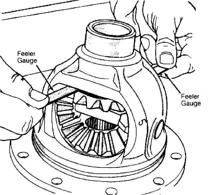
Fig. 4: Checking Side Gear Clearance Courtesy of Chrysler Corp.
2) Remove and discard ring gear bolts (left-hand thread on Cherokee 8 1/4" rear axle). Remove ring gear. Remove pinion gears and
thrust washers. Remove side gears and thrust washers.
Remove yoke nut, washer and pinion yoke. Keep pinion nut
for pinion depth adjustment during reassembly. Remove pinion gear,
pinion bearings and preload shims. Discard collapsible spacer.
Remove pinion seal and rear pinion bearing race. Remove
and retain pinion depth shim located under rear bearing race. Remove
pinion front bearing race. Press off pinion gear rear bearing from
pinion gear See Fig. 5. On front axles, remove inner axle housing
seals.
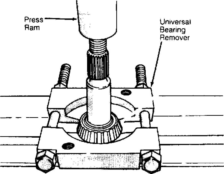
Fig. 5: Pressing Off Pinion Gear Rear Bearing Courtesy of Chrysler Corp.
CLEANING & INSPECTION
Clean and inspect all parts. Replace any worn, cracked, chipped or broken parts. Replace ring and pinion gears as a complete set if either gear is worn or damaged. If necessary, axle and differential pinion gears must be replaced as a complete set. Inspect carrier case for wear and cracks, and replace it if necessary.
REASSEMBLY
NOTE: Ensure correct shims are chosen to obtain proper ring gear backlash and bearing preload before reassembly. See
ADJUSTMENTS.
Pinion Gear
1) Install oil slinger (front axle). Press rear bearing on
pinion gear shaft. Place original shim (or see ADJUSTMENTS) in rear
bearing bore, and install rear bearing race.
NOTE: Install shim so chamfered side is toward bottom of rear bearing bore.
On all axles, install front bearing race into housing.
Install pinion gear. Install front bearing over pinion gear. Apply oil
to seal. Install seal, yoke, washer and original pinion nut. Tighten
nut to remove bearing end play only.
Remove original pinion nut, washer, yoke and front
bearing. Install NEW collapsible spacer on pinion. Reinstall
components and front oil slinger (if equipped) in order using NEW
pinion nut.
Preload pinion bearing. See PINION SEAL & YOKE under
REMOVAL & INSTALLATION. Using an INCH-lb. torque wrench, check pinion
bearing preload by measuring torque needed to rotate pinion gear. See
PINION BEARING PRELOAD SPECIFICATIONS table. If preload is not within
specification, see PINION BEARING PRELOAD under ADJUSTMENTS.
PINION BEARING PRELOAD SPECIFICATIONS TABLE
Applications INCH Lbs. (N.m)
Models 30 & 35 Axle
New Bearing 20-40 (2-5)
Original Bearing 10-20 (1-2)
8 1/4" Ring Gear 10-20 (1-2)
Differential Carrier
Assemble side gears with thrust washers, and install into
carrier. Replace side gear thrust washers if one or both side
clearance checked during disassembly was greater than specification.
See SIDE GEAR CLEARANCE SPECIFICATIONS table under DISASSEMBLY.
Install carrier pinion gears and thrust washers into
carrier. Using Bearing Puller (J-22888) and Thrust Pad (J-22888-9),
remove carrier bearings. See Fig. 6. Note if shims are used between
carrier bearing and carrier.
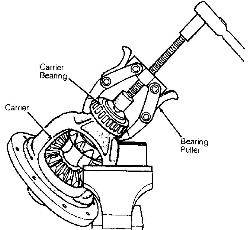
Fig. 6: Removing Drive Axle Carrier Bearings Courtesy of Chrysler Corp.
Install shims (if equipped), and press carrier bearings
onto carrier. Using heat lamp, heat ring gear to 250F (121C).
Install ring gear on carrier. Install NEW ring gear bolts (LEFT-HAND
thread on Cherokee with 8 1/4" rear axle).
Tighten ring gear bolts to specification. To complete
reassembly, see DIFFERENTIAL CARRIER & PINION under REMOVAL &
INSTALLATION. Check ring gear backlash. See RING GEAR BACKLASH under
ADJUSTMENTS.
ADJUSTMENTS
 NOTE:
NOTE:
Ring and pinion gears are serviced as matched set only. They are identified by numbers etched on gear and pinion. See Fig. 7. First number (2 or 3 digits) identifies matched set. Second number on pinion gear (preceded by a "+" sign) is pinion depth variance. This number indicates amount (in thousandths of an inch) gear set varied from standard setting. See PINION GEAR STANDARD DEPTH SPECIFICATIONS table.
Pinion Variance
Fig. 7: Matching Ring & Pinion Gear Set Courtesy of Chrysler Corp.
PINION GEAR STANDARD DEPTH SPECIFICATIONS TABLE
Application
Front Axle (Models 30)
Standard Depth: In. (mm)
2.250 (57.15)
Rear Axle
Model 35
8 1/4" Ring Gear
2.095
(53.29) . . N/A
DETERMINING CORRECT PINION STARTING SHIM
If original ring and pinion are being installed, use
original shim. If new parts (gear set) are being installed, use
following steps to determine best starting shim thickness.
Check numbers etched on drive pinion and ring gear.
Measure thickness of original pinion shim. Note variance number on
pinion gear. See Fig. 7. Note where old and new pinion marking columns
intersect on chart. See Fig. 8.
Intersecting figure represents amount needed to add or
subtract from original shim. For example, if old pinion is +1 and new
pinion is -3, intersecting figure is +.004" (+.10 mm). Add this amount
to original shim. If old pinion is -3 and new pinion is -2,
intersecting figure is -.001" (-.025 mm). See Fig. 8. Subtract this
amount from original shim.
|
OLD PINION MARKING |
NEW PINION MARKING |
||||||||
|
-4 |
-3 |
-2 |
-1 |
+ 0 |
+ 1 |
+ 2 |
+ 3 |
+ 4 |
|
|
+ 4 |
+ 0.008 |
+0.007 |
+ 0.006 |
+ 0.005 |
+0.004 |
+ 0.003 |
+0.002 |
+ 0.001 |
0 |
|
+ 3 |
+ 0.007 |
+0.006 |
+ 0.005 |
+ 0.004 |
+ 0.003 |
+0.002 |
+0.001 |
0 |
-0.001 |
|
+ 2 |
+ 0.006 |
+ 0.005 |
+ 0.004 |
+ 0.003 |
+ 0.002 |
+ 0.001 |
0 |
-0.001 |
-0.002 |
|
+ 1 |
+ 0.005 |
+0.004 |
+ 0.003 |
+ 0.002 |
+ 0.001 |
0 |
-0.001 |
-0.002 |
-0.003 |
|
0 |
+ 0.004 |
+ 0.003 |
+ 0.002 |
+ 0.001 |
0 |
-0.001 |
-0.002 |
-0.003 |
-0.004 |
|
-1 |
+ 0.003 |
+0.002 |
+ 0.001 |
0 |
-0.001 |
-0.002 |
-0.003 |
-0.004 |
-0.005 |
|
-2 |
+ 0.002 |
+0.001 |
0 |
-0.001 |
-0.002 |
-0.003 |
-0.004 |
-0.005 |
-0.006 |
|
-3 |
+ 0.001 |
0 |
-0.001 |
-0.002 |
-0.003 |
-0.004 |
-0.005 |
-0.006 |
-0.007 |
|
-4 |
0 |
-0.001 |
-0.002 |
-0.003 |
-0.004 |
-0.005 |
-0.006 |
-0.007 |
-0.008 |
93ąØ44ąŁąö0
Fig. 8: Pinion Variance Chart Courtesy of Chrysler Corp.
PINION BEARING PRELOAD
1) Apply oil to seal. Install seal, yoke, washer and original
nut. Tighten pinion nut only enough to remove bearing end play. Remove
original nut, washer and yoke and install NEW collapsible spacer.
Reassemble components, including oil slinger (if equipped).
CAUTION: Never reuse collapsible spacer.
2) Place an INCH-lb. torque wrench on pinion nut. Rotate
pinion and note rotating torque. Hold yoke using Yoke Support Wrench
(J-8614-1). Tighten pinion nut until preload torque is 15-25 INCH lbs.
(2-3 N.m). Pinion nut torque should equal or exceed specification. See TORQUE SPECIFICATIONS table. If pinion nut torque does not equal or exceed specification, replace collapsible spacer.
CAUTION: DO NOT overtighten pinion nut. If preload torque is
exceeded, collapsible spacer must be replaced and preload reset.
CARRIER BEARING END PLAY
NOTE: This adjustment is not required on Cherokee 8 1/4" rear axle.
Place bearing race over each carrier bearing. Install
carrier assembly (without ring gear) into axle housing. Install a .
142" (3.60 mm) shim on outer side of each carrier bearing race.
Install bearing caps. Tighten bolts finger tight. Mount
dial indicator to housing. See Fig. 9. Using a pry bar between shims
and housing, move assembly to one side. Zero dial indicator. Pry
assembly to opposite side. Record indicator reading. DO NOT zero or
read indicator while prying.
Indicator reading (when divided by 2; one for each side)
is thickness of shims required. Shims are available in .002" (.050 mm)
increments.
When all side play is eliminated, check drive gear face of
carrier for runout by rotating carrier and reading dial indicator.
Runout should not exceed .002" (.050 mm) . Remove carrier from housing,
and retain shims. See Fig. 9.
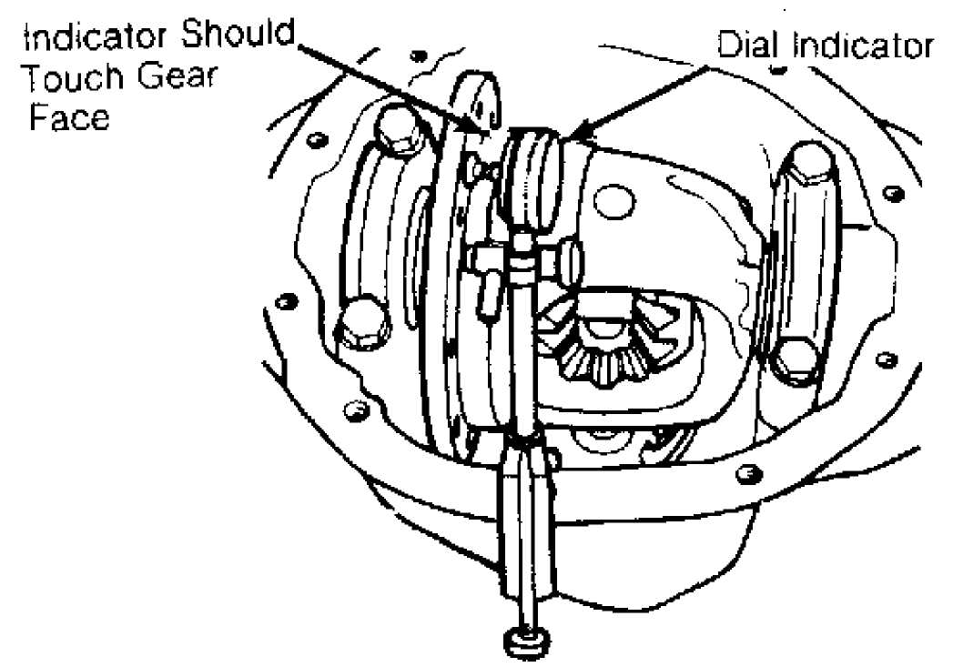
Fig. 9: Checking Carrier Bearing End Play & Runout Courtesy of Chrysler Corp.
RING GEAR BACKLASH
Except Cherokee 8 1/4" Ring Gear
Install carrier assembly into housing using shims selected
to remove end play. Tighten bearing cap bolts evenly to specification.
Attach a dial indicator to housing so button of indicator
contacts drive side of ring gear tooth. Rock ring gear, and note
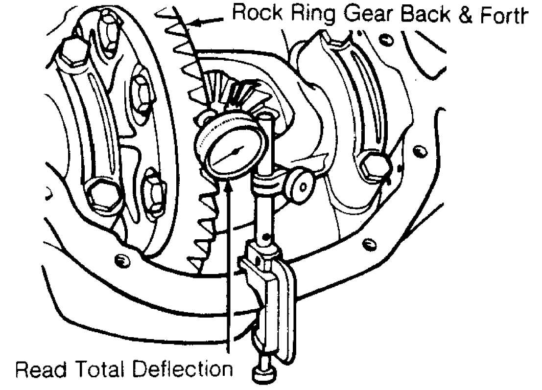
backlash. See Fig. 10.
29232
Fig. 10: Checking Ring Gear Backlash Courtesy of Chrysler Corp.
Backlash should be .005-.009" (.13-.23 mm). To increase
backlash, install thinner shim on ring gear side of case and a thicker
shim on opposite side of case. To decrease backlash, reverse this
step. DO NOT change total shim thickness.
After all adjustments, check gear tooth pattern, and
adjust if necessary. See GEAR TOOTH CONTACT PATTERNS article in
GENERAL INFORMATION.
Cherokee 8 1/4" Ring Gear
1) Using hex adjuster, turn each adjuster until bearing free play is eliminated with about .010" (.25 mm) backlash. To ensure accurate adjustment, seat bearings by rotating differential carrier 1/2 turn, back and forth, 5-10 times each time adjusters are moved.
NOTE: Index gears so same teeth are meshed during all backlash
measurements. Maintain specified adjuster torque to obtain accurate differential bearing preload.
Mount dial indicator on flange. Position indicator stem
against drive side of ring gear. Check backlash every 90 degrees to
find point of minimum backlash. Mark each position so backlash
readings will be taken with same teeth meshed. Rotate ring gear to
point of minimum backlash.
Tighten each adjuster to 10 ft. lbs. (14 N.m). Seat
bearings as instep 1). Measure backlash. If necessary, back out right
or left adjuster and turn in right or left adjuster until backlash is
.003-.004" (.08-.10 mm). Tighten and seat carrier bearings each time
adjusters are moved.
Tighten bearing cap bolts to 100 ft. lbs. (136 N.m). Using
hex adjuster, tighten right adjuster to 70 ft. lbs. (95 N.m). Seat
bearings, and continue to tighten adjuster until torque remains
constant at 70 ft. lbs. (95 N.m).
Check backlash again with indicator. If backlash is not
between .005-.008" (.13-.20 mm), increase torque on right adjuster and
seat bearings. Continue until backlash is .005-.008" (.13-.20 mm).
Tighten left adjuster to 70 ft. lbs. (95 N.m), and seat bearings. With
adjustments completed, install adjuster locks. Make sure lock teeth
are engaged in adjuster threads. Tighten lock bolts to specification.
After all adjustments, check gear tooth pattern and adjust
if necessary. See GEAR TOOTH CONTACT PATTERNS article in GENERAL
INFORMATION.
CARRIER BEARING PRELOAD
NOTE: Pre-loading carrier bearings may change backlash setting. Recheck backlash, and adjust it as necessary.
CAUTION: DO NOT spread housing more than .02" (.5 mm), or damage to housing may result.
Except Cherokee 8 1/4" Ring Gear
Preload carrier bearings by adding .004" (.10 mm) to each
existing shim. Mount Housing Spreader (W-129-A) on axle housing. Mount
dial indicator. Spread housing enough to remove differential. See
Fig. 3.
Position carrier assembly into axle housing bearing bores.
Tap bearing races until fully seated in housing. Remove housing
spreader. Install bearing caps, aligning marks made at disassembly.
Install and tighten bolts. Recheck ring gear backlash.
Cherokee 8 1/4" Ring Gear
Carrier bearings are preloaded during backlash adjustment. See RING GEAR BACKLASH.
TORQUE SPECIFICATIONS
TORQUE SPECIFICATIONS TABLE
Application Ft. Lbs. (N.m)
Axle Housing Cover 20 (27)
Differential Carrier Bearing Caps
Except 8 1/4" Ring Gear 57 (77)
8 1/4" Ring Gear 100 (136)
Drive Shaft "U" Joint Clamp Bolts 14 (19)
Leaf Spring Front Eye Bolts 105 (142)
Leaf Spring Shackle Bolts 95 (129)
Leaf Spring "U" Bolt Nuts 90 (122)
Pinion Yoke Nut
Except 8 1/4" Ring Gear 200 (271)
8 1/4" Ring Gear 210 (285)
Ring Gear Bolts
Except 8 1/4" Ring Gear 45-60 (61-81)
8 1/4" Ring Gear 70 (95)
Wheel Lug Nuts 75 (102)
INCH Lbs. (N.m)
Adjuster Lock Screws (Cherokee, 8 1/4" Ring Gear) 90 (10)
Pinion Shaft Lock Bolt 102 (11)