1993 Jeep Cherokee
AUTOMATIC TRANSMISSIONS
Aisin Warner 4 Electronic Diagnosis
APPLICATION
NOTE: Transmission may also be referred to as AW-4.
TRANSMISSION APPLICATION
Vehicle Application Transmission Model
Jeep
1987-96 Cherokee AW4
1987-92 Comanche AW4
1987 Grand Wagoneer AW4
1987-90 Wagoneer AW4
1992 Wrangler AW4
NOTE: Vehicle body code may be required when diagnosing or
repairing transmission, as body code may be used instead of vehicle model name. See BODY CODE DESIGNATION table.
BODY CODE DESIGNATION
Vehicle Model Body Code
Cherokee XJ
Comanche MJ
Grand Wagoneer SJ
Wagoneer XJ
Wrangler YJ
DESCRIPTION
The electronic control system for the AW-4 transmission controls transmission shift points and torque converter lock-up. Electronic control system consists of Transmission Control Module (TCM), valve body solenoids, throttle position sensor, speed sensor, neutral safety switch and brake switch.
NOTE: Transmission Control Module (TCM) may be referred to as
Transmission Control Unit (TCU). Neutral safety switch may be referred to as park/neutral safety switch or gear select switch.
OPERATION
TRANSMISSION CONTROL MODULE (TCM)
The TCM determines shift points and torque converter lock-up based on input signals received from throttle position sensor, neutral safety switch, speed sensor and brake switch. The TCM controls transmission shift points and torque converter lock-up by operating electric solenoids mounted on the valve body.
The TCM contains a self-diagnostic system used for determining an electronic component failure. The TCM self-diagnostic
system will store a diagnostic trouble code in the TCM memory if certain electronic problems exist. If electronic problem goes away, diagnostic trouble code will be erased from TCM memory after ignition has been cycled approximately 75 times.
NOTE:
Diagnostic trouble code may be referred to as fault code.
Diagnostic trouble codes can be retrieved using a Diagnostic Readout Box-II (DRB-II). After repairing an electrical system problem, stored diagnostic trouble code must be cleared from TCM memory.
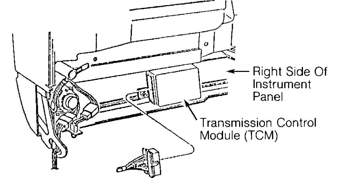
The TCM is located behind right side of instrument panel on Cherokee. See Fig. 1.
94F38401
Fig. 1: Transmission Control Module (TCM) I.D. (Cherokee) Courtesy of Chrysler Corp.
VALVE BODY SOLENOIDS
Valve body solenoids, mounted on the valve body, are output devices controlled by signals received from the TCM. See Fig. 2. The No. 1 and 2 valve body solenoids control transmission shifts while the No. 3 valve body solenoid is used for torque converter lock-up.
When No. 1 and 2 valve body solenoids are energized, solenoid plunger moves from seat. This opens the drain port and releases line pressure. When either valve body solenoid is de-energized, plunger closes the drain port.
The No. 3 valve body solenoid operates in reverse. When No. 3 valve body solenoid is de-energized, solenoid plunger moves away from seat. This opens the drain port and releases line pressure. When No. 3 valve body solenoid is energized, the plunger closes the drain port.
NOTE: For valve body solenoid usage, see VALVE BODY SOLENOID APPLICATION table.
VALVE BODY SOLENOID APPLICATION (1)
Shift Lever Position
"D" (Drive) 1st Gear 2nd Gear 3rd Gear . 4th Gear .
II Q II
1st Gear 2nd Gear 3rd Gear
"1-2" 1st Gear 2nd Gear
No. 1 Solenoid
ON ON OFF OFF
ON ON OFF
ON ON
No. 2 Solenoid
OFF ON ON
OFF
OFF ON ON
OFF ON
"R" (Reverse) "N" Or "P"
ON ON
OFF OFF
(1)
- Valve body contains 3 valve body solenoids. See Fig. 2. No. 1 and 2 valve body solenoids are used for controlling transmission shifts. No. 3 valve body solenoid is used for torque converter lock-up only.
 No. 2 Valve Body Solenoid
92F13511
Fig. 2: Identifying Valve Body Solenoids Courtesy of Chrysler Corp.
BRAKE SWITCH
Brake switch is an input device mounted above the brake pedal. When brake pedal is operated, brake switch delivers an input signal to the TCM. The TCM uses input signal for controlling No. 3 valve body solenoid for torque converter lock-up.
NEUTRAL SAFETY SWITCH
NOTE: Neutral safety switch may be referred to as park/neutral safety switch or gear select switch.
Neutral safety switch is an input device mounted on the transmission manual valve shaft. Neutral safety switch delivers an input signal to TCM, indicating transmission manual valve gear position.
SPEED SENSOR
Speed sensor, mounted in adapter housing or extension
housing, is an input device consisting of speed sensor rotor and speed sensor. Speed sensor rotor is mounted on transmission output shaft. Input signal is delivered from speed sensor to TCM with each revolution of transmission output shaft. The TCM uses input signal for controlling transmission operation.
THROTTLE POSITION SENSOR (TPS)
The TPS, mounted on throttle body, determines throttle position and delivers an input signal to TCM. The TCM uses input signal for controlling transmission upshifts and torque converter lock-up.
SELF-DIAGNOSTIC SYSTEM
DIAGNOSTIC PROCEDURE
When performing vehicle diagnosis:
Ensure transmission fluid level is correct and fluid is
neither contaminated nor aerated.
Ensure shift cable is properly adjusted. Refer to the
appropriate TRANSMISSION SERVICING - A/T article in
this section.
Ensure battery is fully charged.
Perform visual inspection, ensuring all electrical
connections at transmission, TCM, throttle position sensor,
neutral safety switch, speed sensor and brake switch are
clean and properly installed.
Perform TEST 1A - VERIFICATION OF THE COMPLAINT under TROUBLE
SHOOTING CHARTS in this article.
Repair diagnostic trouble codes in order displayed.
Always perform TEST 2A - VERIFICATION TEST after repair is
completed. See TEST 2A - VERIFICATION TEST under TROUBLE
SHOOTING CHARTS in this article.
RETRIEVING DIAGNOSTIC TROUBLE CODES
NOTE: Manufacturer recommends using ChryslerÆs Diagnostic Readout Box-II (DRB-II) with proper cartridge for system diagnosis. Other after-market scan tools may be used for system diagnosis. The following procedure is for DRB-II scan tool usage. Use manufacturerÆs instruction for operating the
DRB-II scan tool. When retrieving diagnostic trouble codes using DRB-II, you must first enter AW4 MENU and then retrieve diagnostic trouble codes.
NOTE: Ensure TEST 1A - VERIFICATION OF THE COMPLAINT is performed when trouble shooting the vehicle. This test checks for diagnostic trouble codes with vehicle stationary and during road test. See TEST 1A - VERIFICATION OF THE COMPLAINT under TROUBLE SHOOTING CHARTS.
NOTE: The DRB-II scan tool can be used in several different modes using manufacturerÆs instructions to activate system components and perform several tests on transmission. See DRB-II OPERATING MODES.
Entering AW4 MENU
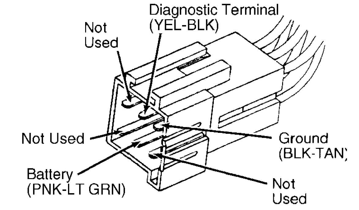
1) Ensure ignition is off. Connect DRB-II to 6-pin
transmission diagnostic connector. See Fig. 3. Transmission diagnostic connector is located to the right of the steering column on driverÆs side of instrument panel above accelerator pedal or below glove box on passengerÆs side.
 94F38427
Fig. 3: Diagnostic Connector & Terminals I.D. Courtesy of Chrysler Corp.
(Cherokee)
2) Turn ignition on. Copyright date and diagnostic program will be briefly displayed. If DRB-II displays an error message, proceed to DRB-II PROBLEMS & ERROR MESSAGES. The following are possible error messages that may appear.
CARTRIDGE ERROR
HIGH BATTERY
KEYPAD TEST FAILURE
LOW BATTERY
RAM TEST FAILURE
If no error messages appear, display will read as follows
after a few seconds: 1) VEHICLES TESTED, 2) HOW TO USE, 3) CONFIGURE
and 4) SELECT SYSTEM.
Select 4) SELECT SYSTEM to enter diagnostic system. Once
in SELECT SYSTEM, select 2) TRANSMISSION to enter transmission.
Display will read 1) EATX and 2) AW4.
Select 2) AW4. After a few seconds display will change to
read AW4, VERSION 01. After a few seconds, display will read AW4 MENU,
1) SYSTEM TEST and 2) READ FAULTS. If DOWN ARROW is depressed 3 times,
display will read as follows: 3) STATE DISPLAY, 4) ACTUATOR TESTS and
5) ADJUSTMENTS.
NOTE: The ACTUATOR TESTS and ADJUSTMENTS cannot be used when diagnosing the AW-4 transmission.
Retrieving Diagnostic Trouble Codes
Select 2) READ FAULTS from AW4 MENU. If no diagnostic
trouble code exists, display will read as follows: AW4 FAULTS, NO
FAULTS DETECTED.
If diagnostic trouble code exists, the following message
will be displayed: 1 OF 3 FAULTS. This number will vary depending on
number of diagnostic trouble codes stored in the TCM memory.
Diagnostic trouble code and message will be displayed.
Press DOWN ARROW key to display next diagnostic trouble code. To
identify diagnostic trouble code, see DIAGNOSTIC TROUBLE CODE
IDENTIFICATION table.
NOTE: See TROUBLE SHOOTING CHARTS to diagnose faults indicated by trouble codes.
NOTE: Valve body solenoid diagnostic trouble code 700 may appear in a FAULT PRESENT or FAULT STORED status. Status will be displayed along with diagnostic trouble code. Diagnostic trouble code must be diagnosed depending on the status. See TEST 1A - VERIFICATION OF THE COMPLAINT under TROUBLE SHOOTING CHARTS.
DIAGNOSTIC TROUBLE CODE IDENTIFICATION
Trouble Code Problem Area
700 (1) Valve Body Solenoid
702 Speed Sensor
703 (2) Gear Select Switch
705 Throttle Position Sensor
706 Brake Switch
707 Wrong TCM Or TCU
(1) - Trouble code may apply to individual valve body
solenoids. Valve body solenoid may be referred to as S1 for No. 1, S2 for No. 2 and S3 for No. 3.
(2) - Gear select switch is the same as the neutral
safety switch.
CLEARING DIAGNOSTIC TROUBLE CODES
1) Once all diagnostic trouble codes have been obtained,
diagnostic trouble code(s) can be erased from TCM memory by
disconnecting electrical connector from TCM for at least 15 seconds.
CAUTION: DO NOT disconnect battery, as data stored in other vehicle control modules will be lost.
2) The TCM is located behind right side of instrument panel
on Cherokee. See Fig. 1.
DRB-II OPERATING MODES
NOTE: The DRB-II can be operated in several different modes to
perform various tests. Except for voltmeter/ohmmeter and HOW TO USE modes, all other operating modes are selected from AW4 MENU. See ENTERING AW4 MENU under RETRIEVING DIAGNOSTIC TROUBLE CODES.
VOLTMETER/OHMMETER MODE
To access voltmeter/ohmmeter mode, connect Red volt-ohmmeter test lead to Red port at top right corner of DRB-II. There are 2 different ports on top of DRB-II; ensure test lead is connected to proper port. Access voltmeter or ohmmeter mode using manufacturerÆs instructions.
NOTE: The DRB-II is grounded through transmission diagnostic connector and only one test lead is required. When diagnosing transmission, an external volt-ohmmeter may sometimes be required.
HOW TO USE MODE
This mode gives instructions on DRB-II usage. To enter
this mode, see steps 1) through 4) of ENTERING AW4 MENU under
RETRIEVING DIAGNOSTIC TROUBLE CODES. Select 2) HOW TO USE.
A series of screens will be displayed explaining DRB-II
key usage for system diagnosing.
SYSTEM TEST MODE
NOTE: SYSTEM TEST mode consists of a stationary test and a road test. The SYSTEM TEST mode must be selected from AW4 MENU. See ENTERING AW4 MENU under RETRIEVING DIAGNOSTIC TROUBLE CODES.
Stationary test monitors transmission system data, current
valve body solenoid failures, switch failures, correct TCM
application, calibration and operation. Road test checks all valve
body solenoids and speed sensor.
Technician will be instructed to place shift lever in each
gear position, starting by shifting into 1-2 position. Once
transmission is in Park, brake pedal must be depressed to check brake
switch.
After brake switch is checked, technician will be
instructed to slowly depress throttle. DRB-II will display 7 asterisks (*******) corresponding to throttle position. While depressing accelerator, Throttle Position Sensor (TPS) sweeps through entire range of positions required by the TCM.
4) A corresponding asterisk will be cleared from DRB-II
display as each throttle position is sensed by TCM. Several attempts
may be required to clear all asterisks from the display, depending on
how fast accelerator is depressed.
After throttle position is checked, technician will be
instructed to drive the vehicle. The DRB-II will indicate if a
requested action is seen by the TCM. If technician is requested to
perform a particular operation and TCM does not acknowledge the
action, press ENTER key to continue testing.
The TCM will instruct technician to accelerate vehicle at
light throttle to ensure transmission shifts through all gears,
indicating proper valve body solenoid operation.
During road test, ensure vehicle can be accelerated slowly
and evenly to allow transmission to enter all gear ranges without
downshifting or braking. If a failure is sensed, a diagnostic trouble
code will be displayed on DRB-II.
NOTE: If TCM senses a failure, control logic activates a specified valve body solenoid to obtain a certain gear depending on failure. Because transmission diagnostic trouble codes are displayed one at a time, multiple diagnostic trouble codes must be identified by retesting transmission.
STATE DISPLAY MODE
NOTE: STATE DISPLAY mode must be selected from AW4 MENU. See
ENTERING AW4 MENU under RETRIEVING DIAGNOSTIC TROUBLE CODES . Select 3) STATE DISPLAY on DRB-II.
Module Information
When selecting module information option, the TCM version will be indicated by a 2-digit number. Information can be used to verify proper TCM application.
Sensor
When selecting sensor option, TPS and RPM indications will
be shown. The TPS indicator will display a 7 segment bar graph,
indicating TPS position and throttle plate angle.
A properly operating TPS should indicate 7 segments
through full throttle travel. The RPM indicator will display
transmission output shaft revolutions per minute.
Brake Switch Or Input/Output
Display indicates brake switch status, indicating whether brake pedal is applied or released. Display also indicates shift lever position, whether a valve body solenoid is on or off and present transmission operating gear.
DRB-II PROBLEMS & ERROR MESSAGES
CARTRIDGE ERROR
If CARTRIDGE ERROR message is displayed, disconnect DRB-II
from transmission diagnostic connector. DO NOT touch keys on DRB-II
keypad. Reconnect DRB-II to transmission diagnostic connector and note
display.
If CARTRIDGE ERROR message is displayed, replace DRB-II
cartridge and proceed with diagnostics. If KEYPAD TEST FAILURE message
is displayed, replace DRB-II and proceed with diagnostics.
HIGH BATTERY
If HIGH BATTERY message is displayed, use external voltmeter to check battery voltage at battery terminals. If battery voltage is 11.7-13.0 volts, replace DRB-II. If battery voltage is not 11.7-13.0
volts, check charging system.
KEYPAD TEST FAILURE
If KEYPAD TEST FAILURE message is displayed, disconnect
DRB-II from transmission diagnostic connector. DO NOT touch keys on
DRB-II keypad. Reconnect DRB-II to transmission diagnostic connector
and note display.
If KEYPAD TEST FAILURE message is not displayed, proceed
with diagnostics. If KEYPAD TEST FAILURE message is displayed, replace
DRB-II and proceed with diagnostics.
LOW BATTERY
If LOW BATTERY message is displayed, use external voltmeter to check battery voltage at battery terminals. If battery voltage is 11.7-13.0 volts, replace DRB-II. If battery voltage is not 11.7-13.0 volts, check charging system.
RAM TEST FAILURE
If RAM TEST FAILURE message is displayed, disconnect DRB-
II from transmission diagnostic connector. DO NOT touch keys on DRB-II
keypad. Reconnect DRB-II to transmission diagnostic connector and note
display.
If RAM TEST FAILURE message is not displayed, proceed with
diagnostics. If RAM TEST FAILURE message is displayed, replace DRB-II
and proceed with diagnostics. If KEYPAD TEST FAILURE message is
displayed, replace DRB-II and proceed with diagnostics.
COMPONENT TESTING
BRAKE SWITCH
Brake switch is mounted above brake pedal. When brake pedal is operated, brake switch delivers an input signal to TCM. The TCM uses input signal for controlling No. 3 valve body solenoid for torque converter lock-up. No other information is available from manufacturer.
NOTE: For proper brake switch adjustment, see BRAKE SWITCH under REMOVAL & INSTALLATION.
NEUTRAL SAFETY SWITCH
NOTE: Neutral safety switch may be referred to as park/neutral or gear select switch. For proper neutral safety switch adjustment, see NEUTRAL SAFETY SWITCH under REMOVAL & INSTALLATION.
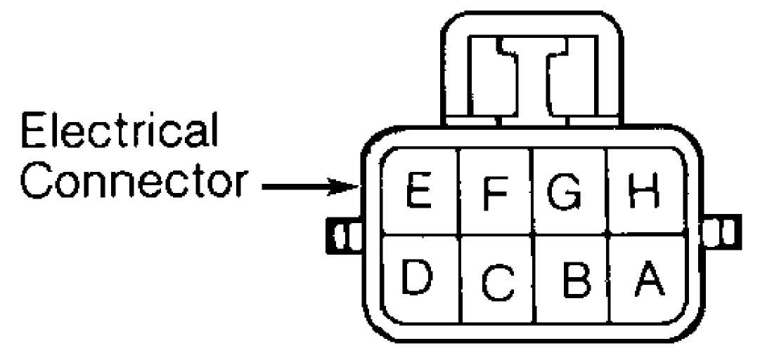
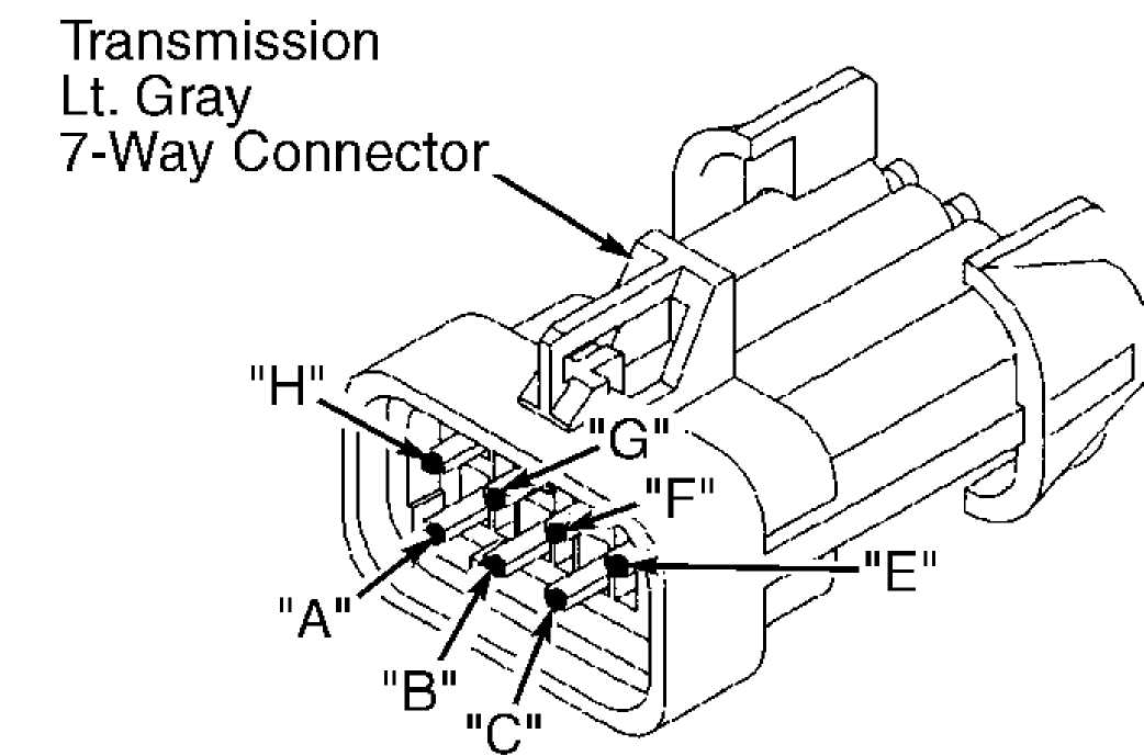
Disconnect electrical connector. Note terminal
identification. See Fig. 4. Using ohmmeter, check continuity between specified terminals in relation to shift lever position. See NEUTRAL SAFETY SWITCH CONTINUITY SPECIFICATIONS table. Replace neutral safety switch if continuity is not as specified.
NEUTRAL SAFETY SWITCH CONTINUITY SPECIFICATIONS
Shift Lever Continuity
Position Between Terminals
Park "B" & "C"
Reverse "A" & "E"
Neutral "B" & "C"
Drive ( 1)
3 "A" & "G"
1-2 "A" & "H"
(1) - No continuity should exist between any terminals.
92H13513
Fig. 4: Identifying Neutral Safety Switch Terminals Courtesy of Chrysler Corp.
SPEED SENSOR
Disconnect electrical connector at speed sensor located on
adapter housing or extension housing. Connect ohmmeter leads between
speed sensor electrical terminals.
Rotate transmission output shaft and note ohmmeter
reading. Ohmmeter needle should fluctuate to indicate speed sensor
operation. Replace speed sensor if no reading is obtained.
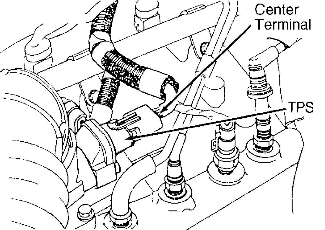
THROTTLE POSITION SENSOR (TPS)
NOTE:
Digital voltmeter must be used to check TPS.
Note location of TPS electrical connector. See Fig. 5.
Turn ignition on. Using digital voltmeter, check output voltage at
center terminal with throttle plate closed (idle position) and wide
open (full throttle).
With throttle plate closed (idle position), output voltage
should be greater than 200 millivolts. With throttle plate wide open
(full throttle), output voltage should be less than 4.8 volts.
Ensure output voltage gradually increases as throttle
plate is moved from closed to wide open throttle. If no voltage
exists, check for defective wiring circuits or connections. Replace
TPS if defective.
92113514
Fig. 5: Identifying TPS Electrical Connector Courtesy of Chrysler Corp.
VALVE BODY SOLENOID
With oil pan removed, disconnect electrical connector from valve body solenoid. Using ohmmeter, check resistance between valve body solenoid electrical terminal and solenoid mounting bracket. Replace valve body solenoid if resistance is not 11-15 ohms.
TROUBLE SHOOTING CHARTS & CODE CHARTS
NOTE: Following trouble shooting charts and illustrations are courtesy of Chrysler Corp. Always start by performing TEST 1A - VERIFICATION OF THE COMPLAINT. When diagnosing transmission, it may be necessary to verify TCM connector terminals, circuits and function, See Fig. 6.
NOTE: When using trouble shooting charts, Transmission Control
Module (TCM) may be referred to as Transmission Control Unit (TCU). Diagnostic trouble code may be referred to as fault code. Neutral safety switch may be referred to as
park/neutral or gear select switch.
94B38431
 D16
D16
CHEROKEE
CAV... CIRCUIT FUNCTION
C1-C2 Not Used
C3 505 TN/BK Trans Speed Sensor
C4 137 YL/BK Auto Trans Diagnostic
C5-C7 Not Used
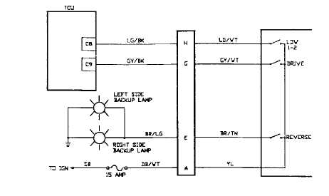
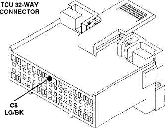
C8 506 LG/BK Low (1-2) Input
C9 507 GY/BK Drive (3) Input
C10 K29WT/PK Brake Input
C11 Not Used
C12-C13 Not Used
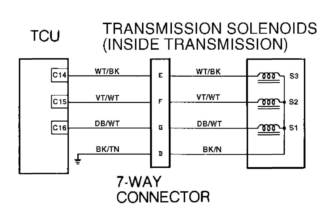
C14 508 WT/BK S3 Solenoid
(Converter Lockup)
C15 509 VT/WT S2 Solenoid
C16 510DB/WT S1 Solenoid
D1 Not Used
D2 K22 OR/DB Throttle Position Sensor
D3 K4BK/LB TPS Signal Ground
D4-D6 Not Used
D7 Z12BK/TN Power Ground
D8-D13 Not Used
D14 A14RD Battery
D15 Not Used
D16 T17 YL Ignition (Run/On)
: TCM Connector Terminals I.D., Circuits
Fig.
Courtesy of Chrysler Corp.
TEST 1A - VERIFICATION OF THE COMPLAINT
GRAND.CHEROKEE
CAV... CIRCUIT FUNCTION
C1-C2 Not Used
C3 T14 LG/WT Trans Speed Sensor
C4 D82 BK/YL Auto Trans Diagnostic
C5-C7 Not Used
C8 T25 LG Low (1-2) Input
C9 T50 DG Drive (3) Input
C10 .... L53 BR Brake Input
C11-C13 Not Used
C14 .... T20 LB/BR S3 Solenoid
(Converter Lockup)
C15 .... T59 PK S2 Solenoid
C16 .... T60 BR/YL S1 Solenoid
D1 Not Used
D2 K22 OR/DB Throttle Position Sensor
D3 K4 BK/LB TPS Signal Ground
D4-D6 Not Used
D7 21 BK Power Ground
D8-D13 ,. Not Used
D14 .... A14 RD/WT Battery
D15 Not Used
D16 .... F86 LB/RD Ignition (Run/On)
& Functions
NOTE: ALWAYS start diagnosis with the most recent code.
1) Begin your testing of the transmission with a thorough visual inspection.
2) Connect the DRB-II to the transmission diagnostic
connector. See RETRIEVING FAULT CODES under SELF-DIAGNOSTIC SYSTEM for diagnostic connector location.
CAUTION: If the vehicle is in 3rd or OD position and feels like it is stuck in 3rd or jumping from 2-1 or 3-1, perform TEST 10A - TESTING FOR INTERMITTENT SPEED SENSOR test below.
With the DRB-II, perform SYSTEM TEST. See SYSTEM TEST MODE
under DRB-II OPERATING MODES.
The DRB-II will instruct you to do some actions during the
System Test. The DRB-II will then look for the action to happen and
automatically go to the next test function. If you perform the
required action and the DRB-II does not move to the next function,
press ENTER. The DRB-II will continue the testing.
When the DRB-II states "VEHICLE DRIVE", the vehicle be
must be driven at a speed above 4 miles per hour to ensure accurate
testing of the vehicle speed sensor. Afterwards, the DRB-II will
display any fault codes that may be present.
When the system test is complete, if there are any fault
codes present, the DRB-II will automatically display the code(s).
There are two types of faults for the transmission
solenoids. They are displayed as "FAULT STORED" and "FAULT PRESENT". Note that the tests are different in the chart below.
8) Perform the tests shown below in response to the indicated
fault codes.
NOTE:
ALWAYS start diagnosis with the most recent code.
CODE-TO-TEST MENU
CODE-TO-TEST MENU
|
Code: |
Solenoid Affected: |
Fault |
Status: |
Perform: |
||
|
None |
None Affected |
No |
Faults |
Test |
2A |
|
|
700 |
Solenoid No. |
1 |
Fault |
Present |
Test |
4A |
|
700 |
Solenoid No. |
1 |
Fault |
Stored |
Test |
ąŚąÉ |
|
700 |
Solenoid No. |
2 |
Fault |
Present |
Test |
4B |
|
700 |
Solenoid No. |
2 |
Fault |
Stored |
Test |
ąŚąÉ |
|
700 |
Solenoid No. |
3 |
Fault |
Present |
Test |
4C |
|
700 |
Solenoid No. |
3 |
Fault |
Stored |
Test |
ąŚąÉ |
|
702 |
Speed Sensor Fault |
Test |
5A |
|||
|
703 |
Gear Select Fault |
Test |
6A |
|||
|
705 |
TPS Fault |
Test |
7A |
|||
|
708 |
Wrong TCU |
Test |
9A |
|||
TEST 2A - VERIFICATION TEST
NOTE: Perform TEST 1A - VERIFICATION OF THE COMPLAINT before proceeding.
This test verifies the correct operation of the AW4
transmission. It must be performed after finding no faults using the DRB-II, and after a vehicle repair has been made.
mounted.
Turn ignition key to "OFF".
Hold the MODE key and press the ATM key on the DRB-II at
the same time to restart the DRB-II.
Turn ignition key to "ON".
Reconnect all previously disconnected connectors.
Verify that the AW4 transmission control unit is properly
Make sure the transmission fluid is at the proper level.
Check the fluid with the transmission temperature hot, the vehicle on
level ground, and the gear selector in neutral.
If any repairs have been made, test the vehicle as
instructed in TEST 1A - VERIFICATION OF THE COMPLAINT, and read faults using the DRB-II. If there are any fault messages present, repeat TEST 1A - VERIFICATION OF THE COMPLAINT.
TEST 3A - STORED DIAGNOSTIC TROUBLE CODES TEST
NOTE: Perform TEST 1A - VERIFICATION OF THE COMPLAINT before proceeding.
At this point, the Visual Inspection has been performed, a
"FAULT STORED" code has been found and the vehicle has been test
driven. The fault code is not "FAULT PRESENT", so it cannot be
considered a CURRENT or HARD fault.
All solenoid circuits are in the same harness and a common
ground wire is used for the solenoids. Use the following figures to
identify the harness and connector to inspect. See Fig. 7 and 8. if
all 3 solenoid faults are present, repair the Black wire (Cherokee)
ground wire open condition.
Carefully inspect the entire suspected circuit. Pay
particular attention to connectors, corrosion, accident damage, and
improper or missing parts.
If any problems are found, make the appropriate repair.
Then perform TEST 1A using the DRB-II.
Erase fault codes.
If no problems are found, perform the SYSTEM TEST using
the DRB-II. Re-check for fault codes. If there are no fault codes,
perform TEST 2A - VERIFICATION TEST. If fault code(s) return, perform
TEST 1A - VERIFICATION OF THE COMPLAINT.
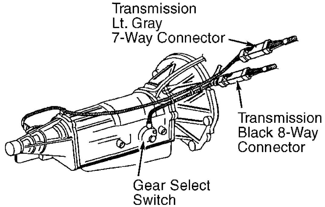
 Transmission
Lt. Gray
Gear Select Switch
- Location of 7-Way Connector
92F13594
Fig. 7: Test 3A
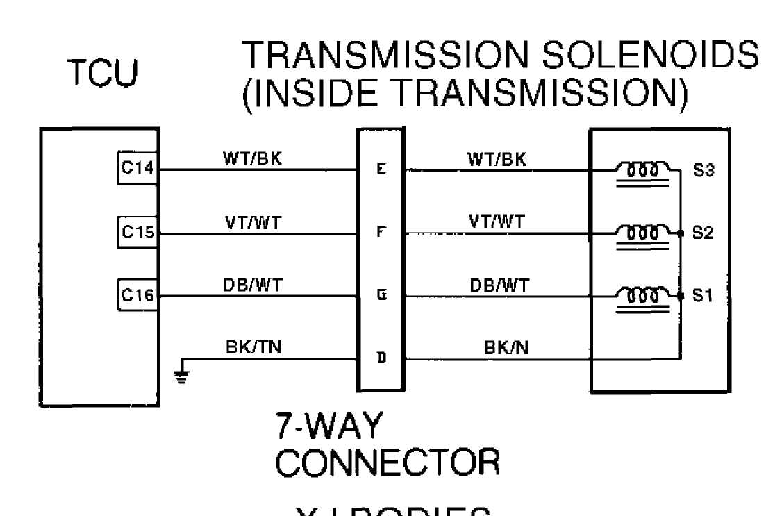
7-Way Connector -
|
A |
B |
ąĪ |
E |
F |
G |
H |
|
BK/YL |
BK/TN |
TfSl/WT |
WT/BK |
VTAVT |
DB/WT |
BK/RD |
92G13595
Fig. 8: Test 3A - View of 7-Way Connector (Cherokee)
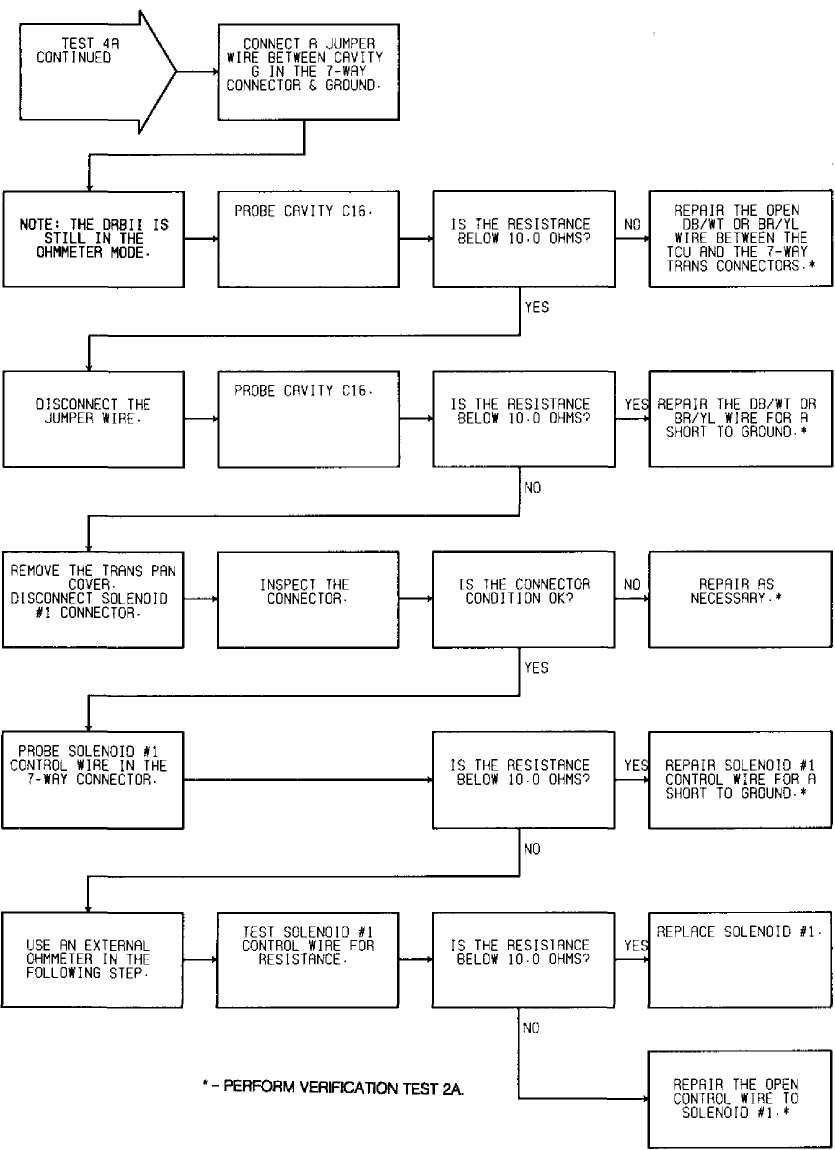
TEST 4A - CODE 700 - S1 SOLENOID CIRCUIT
Perform TEST 1A before proceeding.

Fig. 9: Test 4A - Code 700, Flow Chart (1 of 2)
92J13598
Fig. 10: Test 4A - Code 700, Schematic (Cherokee)
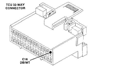
Fig. 11:
92D13600 ZJBody: BR/YL
Test 4A - Code 700, TCU 32-Way Connector (Cavity 16)

 92F13594
Fig. 12: Test 4A - Code 700, Location of 7-Way Connector
 Transmission
Lt. Gray
7-Way Connector
ąÆ
BK
BK/TN
92E13601
- Code 700, Location of Pin "B" (Ground)
Fig. 13: Test 4A
NOTE: See TEST 4A (1 OF 2) for wiring diagram.
92F13602
Fig. 14: Test 4A - Code 700, Flow Chart (2 of 2)
92J13598
Fig. 15: Test 4A - Code 700, Schematic (Cherokee)
 Transmission
Lt. Gray
7-Way Connector
92G13603
Fig. 16: Test 4A - 7-Way Connector Cavity "G" (Cherokee)
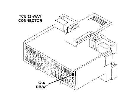
Fig. 17:
92D13600 ZJBody: BR/YL
Test 4A - Code 700, TCU 32-Way Connector (Cavity 16)
 Solenoid #2
92ą?3605 Connector
Fig. 18: Test 4A - Code 700, Location of Solenoids
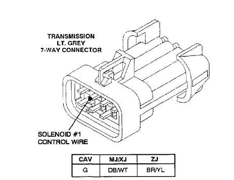
Fig. 19:
92J13606
Test 4A - Code 700, Solenoid No. 1 Wire (Cavity "G")
92A13607
 Fig. 20: Test 4A - Code 700, Testing S1 Control Wire
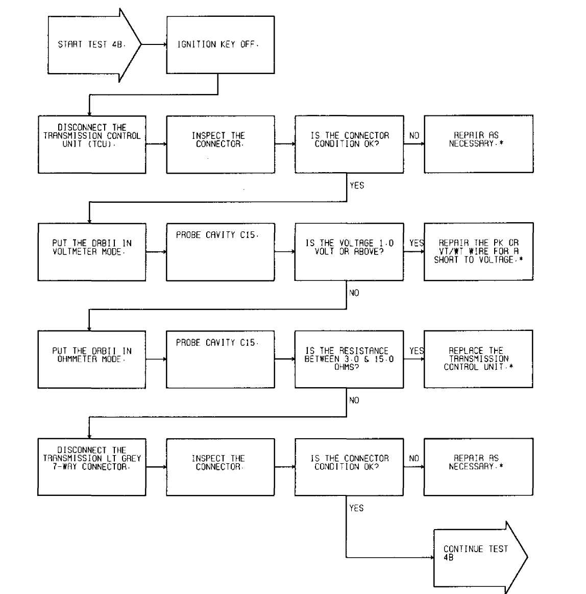
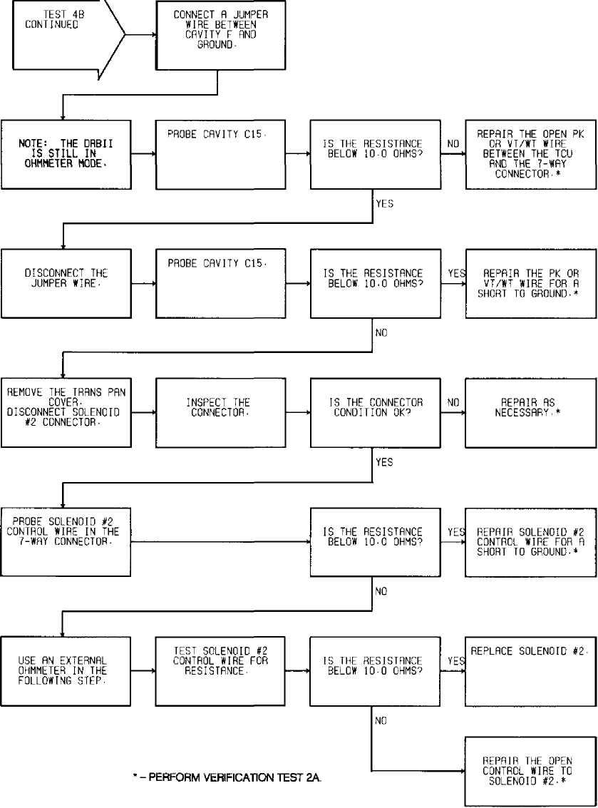
TEST 4B - CODE 700 - S2 SOLENOID CIRCUIT
Perform TEST 4A before proceeding.
92B13608 ŌĆó-PERFORM VERIFICATION TEST 2A.
Fig. 21: Test 4B - Code 700, Flow Chart (1 of 2)
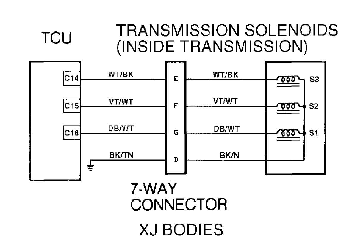
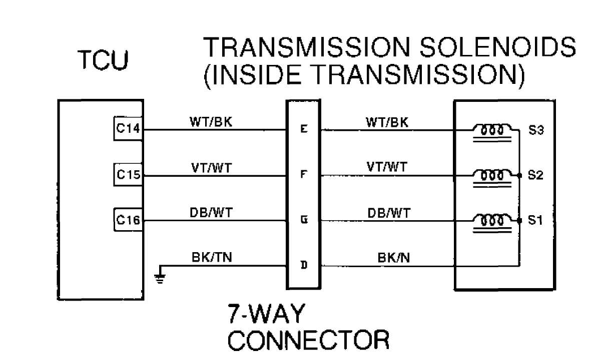
92J13598
Fig. 22: Test 4B - Code 700, Schematic (Cherokee)
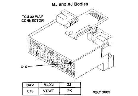
Fig. 23: Test 4B - Code 700, TCU 32-Way Connector (Cavity 15)

 92F13594
Fig. 24: Test 4B - Code 700, Location of 7-Way Connector
NOTE: See TEST 4B (1 OF 2) for wiring diagram.
92F13610
Fig. 25: Test 4B - Code 700, Flow Chart (2 of 2)
92J13598
Fig. 26: Test 4B - Code 700, Schematic (Cherokee)
 Transmission
Lt. Gray
7-Way Connector
I.
XJ BODY
92G13611
Fig. 27: Test 4B - 7-Way Connector Cavity "F" (Cherokee)

Fig. 28: Test 4B - Code 700, TCU 32-Way Connector (Cavity 15)
 92ą?3605 Connector
Fig. 29: Test 4B - Code 700, Location of Solenoids

Fig. 30: Test 4B - Code 700, Solenoid No. 1 Wire (Cavity "F")
 Transmission
Lt. Gray
7-Way Connector
I
92J136U Solenoid #2
92J136UConnector
Fig. 31: Test 4B - Code 700, Testing S2 Control Wire
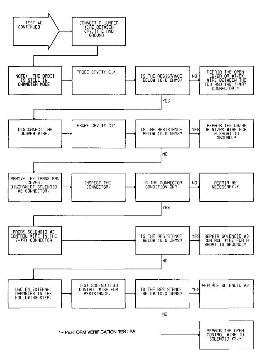
TEST 4C - CODE 700 - S3 SOLENOID CIRCUIT
Perform TEST 4A before proceeding.
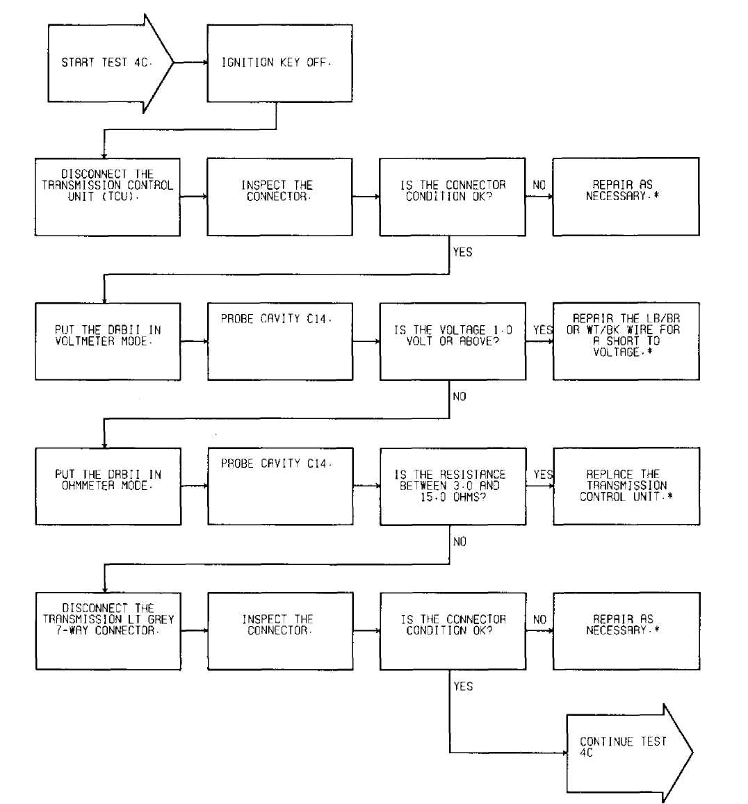 * - PERFORM VERIFICATION TEST 2A.
ąŁ2ąÉ13615
Fig. 32: Test 4C - Code 700, Flow Chart (1 of 2)
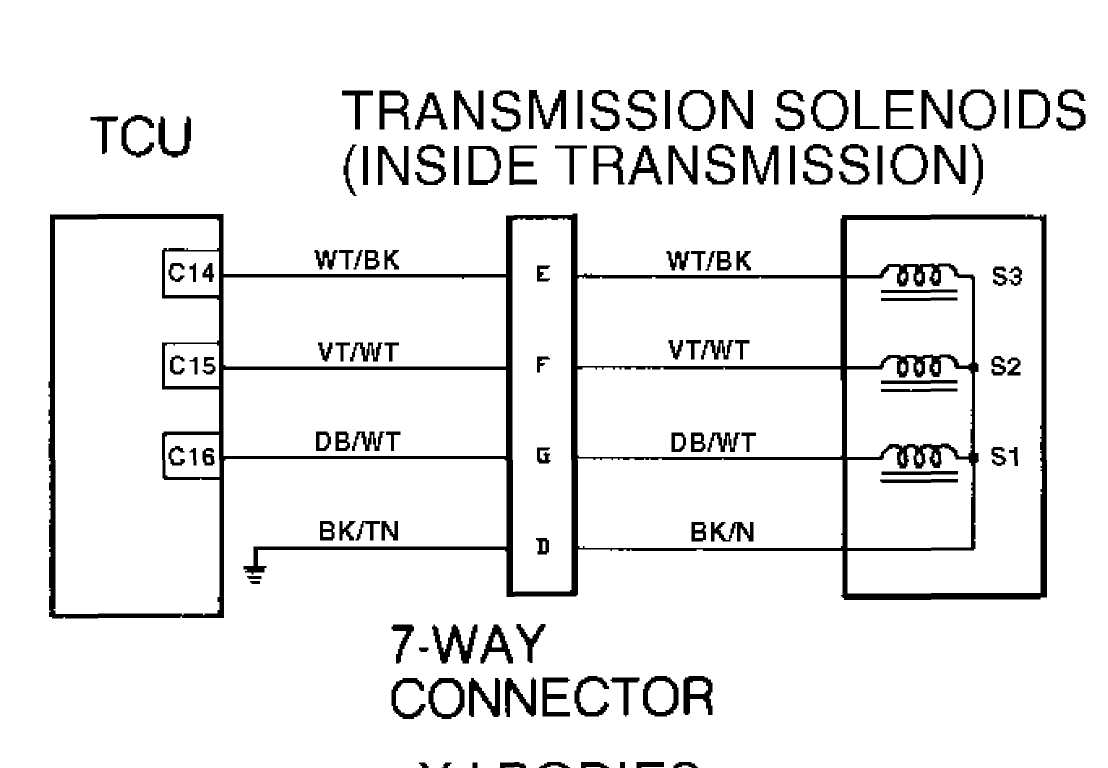
 92J13598
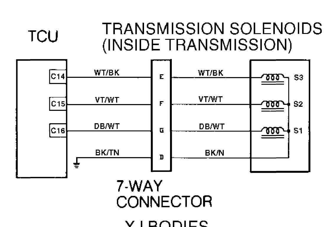
Fig. 33: Test 4C - Code 700, Schematic (Cherokee)
92B13616 XJ BODY
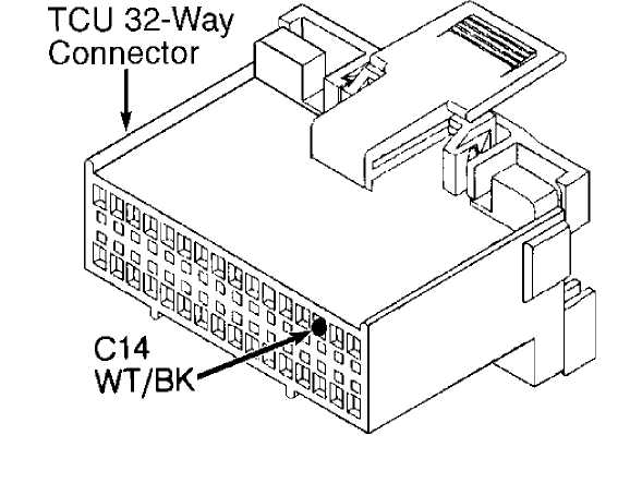
Fig. 34: Test 4C - TCU 32-Way Connector (Cavity 14, Cherokee)
 Fig.
Fig.
92F13594
35: Test 4C - Code 700, Location of 7-Way Connector
NOTE: See TEST 4C (1 OF 2) for wiring diagram.
92D13618
Fig. 36: Test 4C - Code 700, Flow Chart (2 of 2)
92J13598
Fig. 37: Test 4B - Code 700, Schematic (Cherokee)
 Transmission
Lt. Gray
7-Way Connector
XJ BODY
ąŁ2ąĢ13619
Fig. 38: Test 4C - 7-Way Connector Cavity "E" (Cherokee)
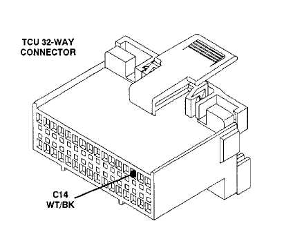
Fig. 39:
ZJ Body: LB/BR 92ą?3621
Test 4C - Code 700, TCU 32-Way Connector (Cavity 14)
 92ą?3605 Connector
Fig. 40: Test 4C - Code 700, Location of Solenoids
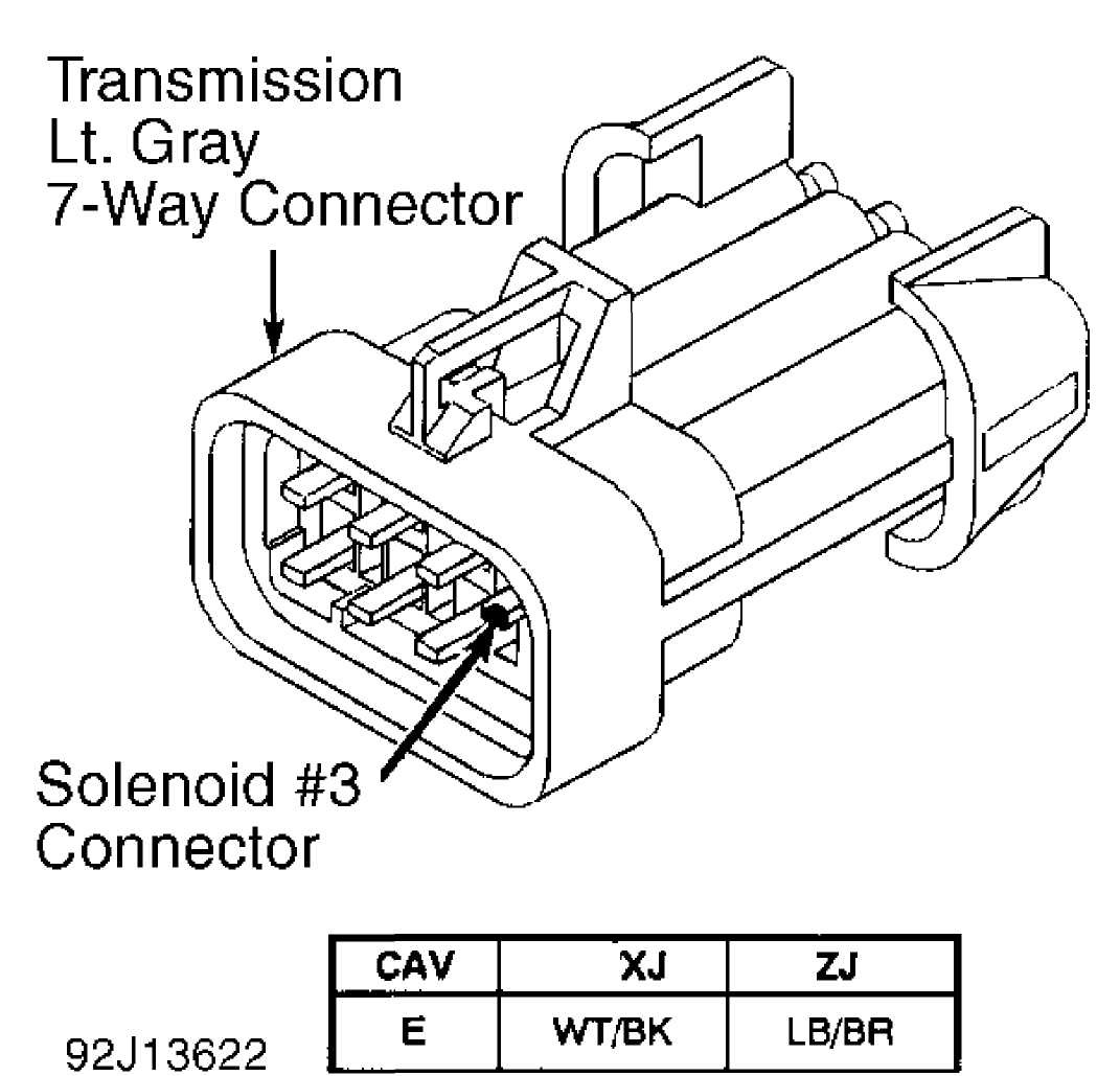
Fig. 41: Test 4C - Code 700, Solenoid No. 1 Wire (Cavity "E")
Transmission
LI. Gray
7-Way Connector
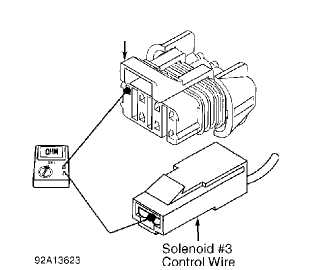
Fig. 42: Test 4C - Code 700, Testing S3 Control Wire
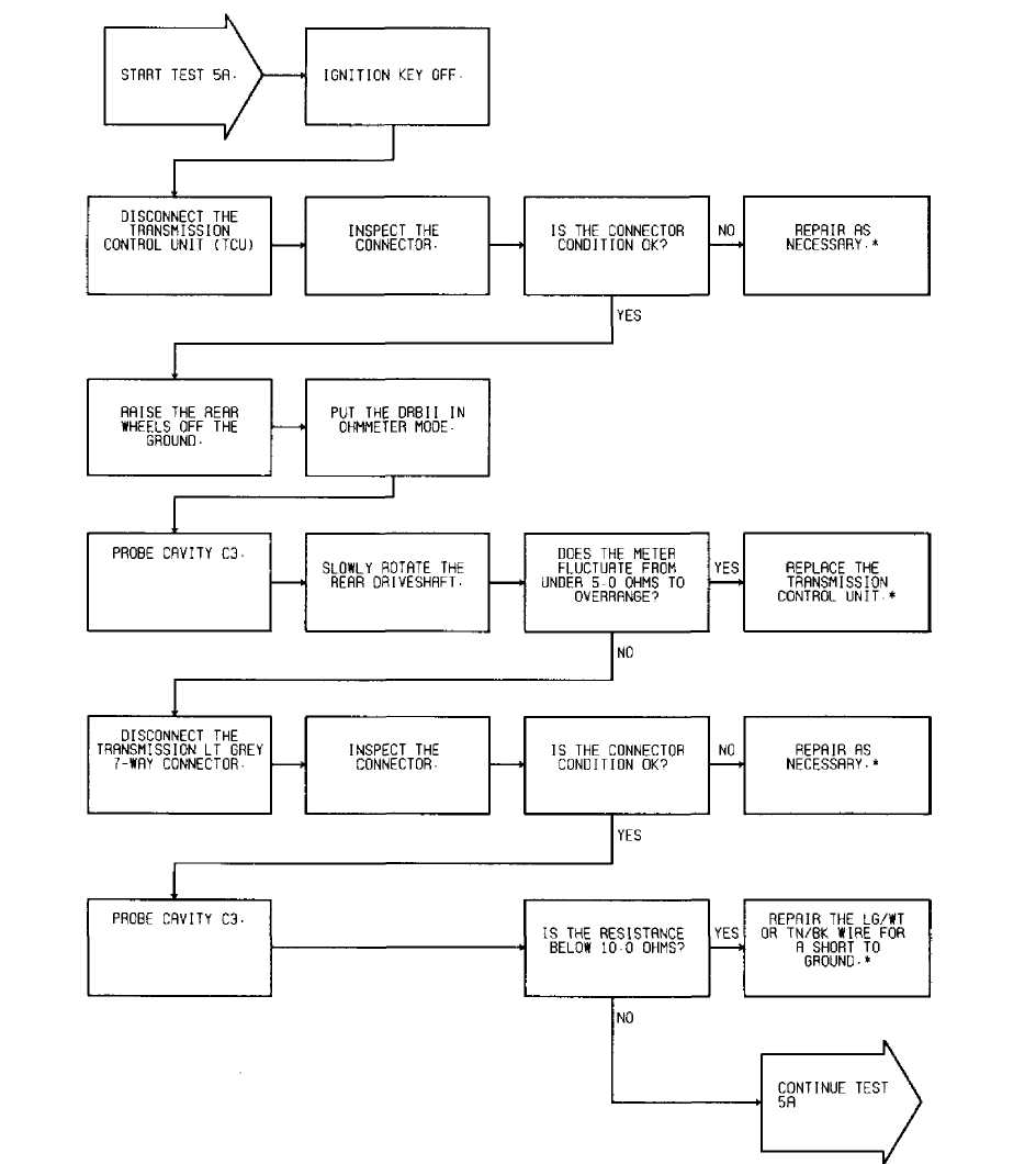
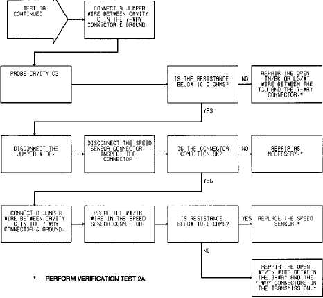
TEST 5A - CODE 702 - SPEED SENSOR CIRCUIT
NOTE: Perform TEST 1A - VERIFICATION OF THE COMPLAINT before proceeding.
Perform TEST 1A before proceeding.
" - PERFORM VERIFICATION TEST 2A. 94H38445
Fig. 43: Test 5A - Code 702, Flow Chart (1 of 2)

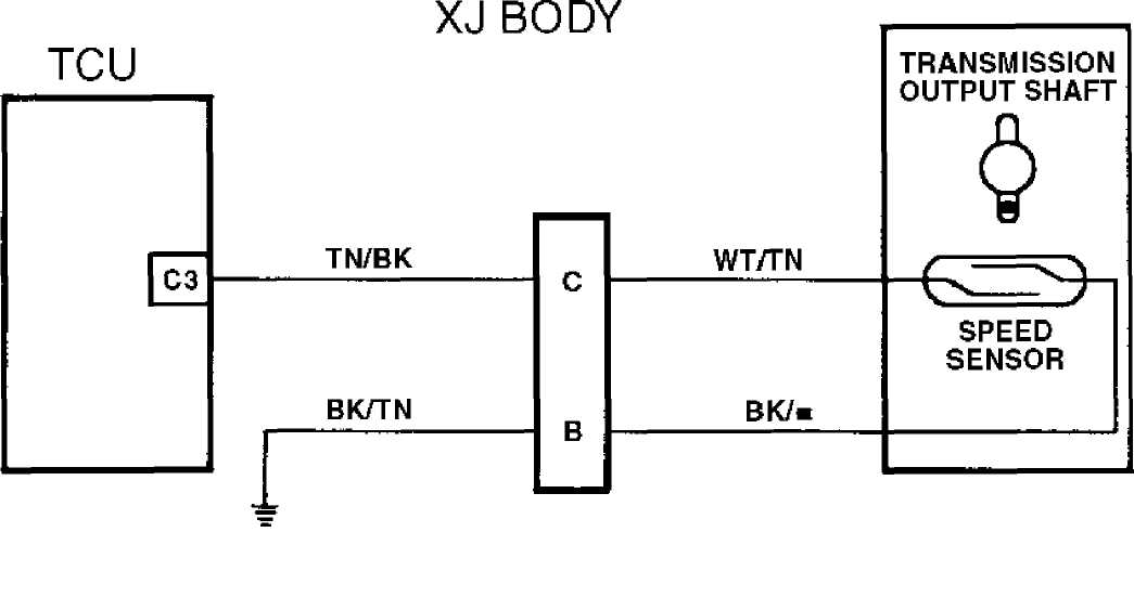
7-WAY
94D38433 CONNECTOR
Fig. 44: Test 5A - Code 702, Speed Sensor Schematic (Cherokee)
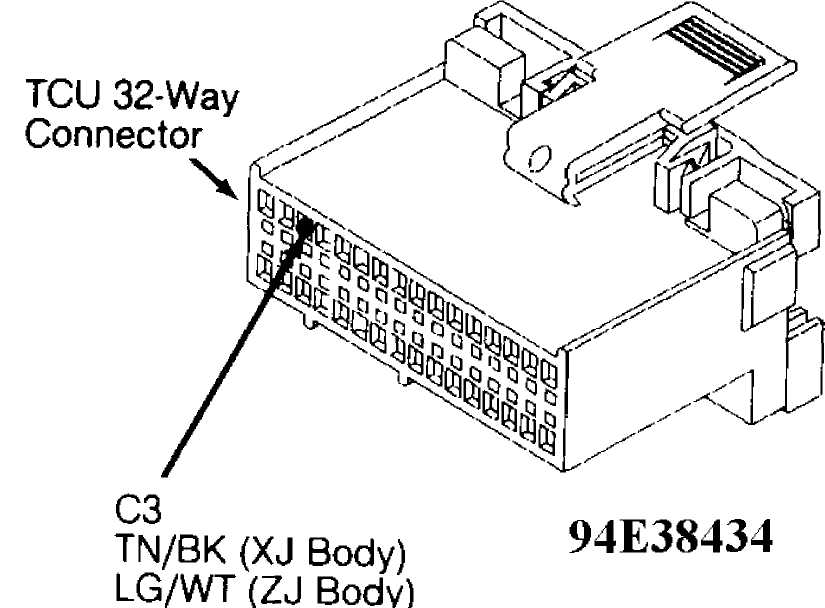
Fig. 45: Test 5A - Code 702, TCU 32-Way Connector (Cavity 3)
 92F13594
Fig. 46: Test 5A - Code 702, Location of 7-Way Connector
NOTE: See TEST 5A (1 OF 2) for wiring diagram.
94F3B435
Fig. 47: Test 5A - Code 702, Flow Chart (2 of 2)
7-WAY
94D38433 CONNECTOR
 Fig. 48: Test 5A - Code 702, Speed Sensor Schematic (Cherokee)
Transmission
Lt. Grey
7-Way Connector
Fig. 49: Test 5A - Transmission 7-Way Connector (Male Side)
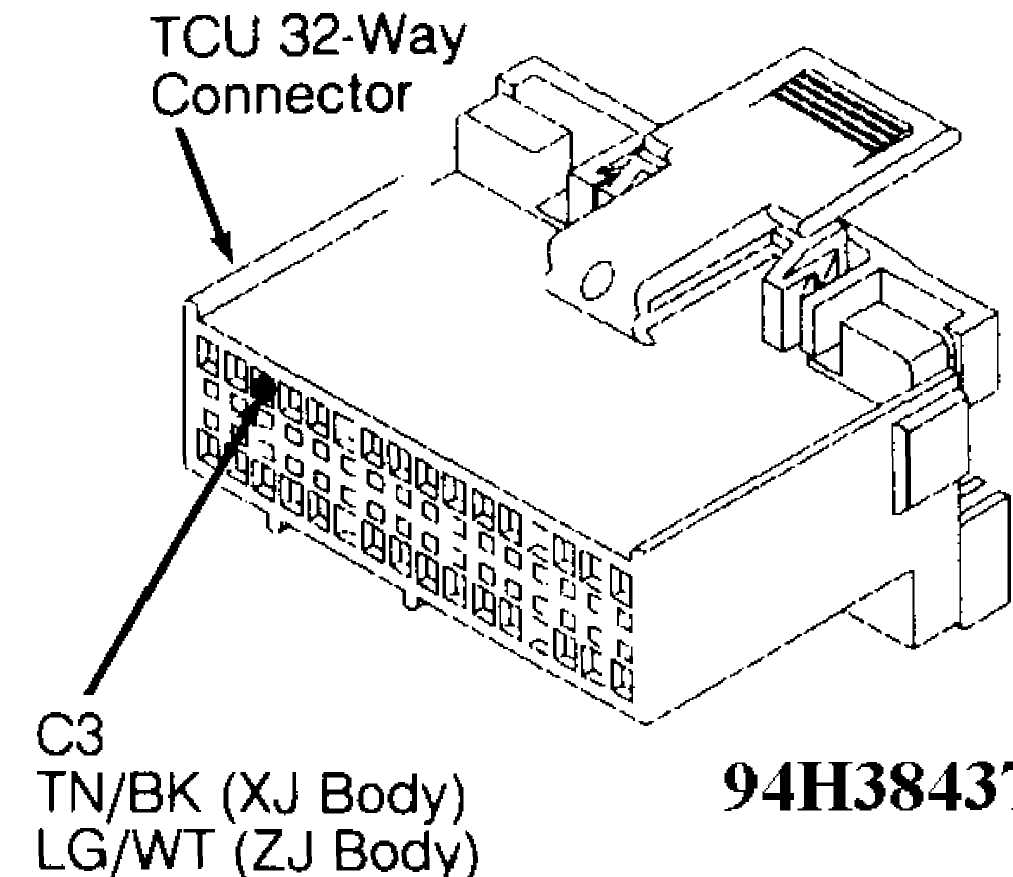
Fig. 50: Test 5A - Code 702, TCU 32-Way Connector (Cavity 3)
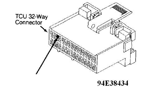 Fig. 51:
C3
TN/BK (XJ Body)
LG/WT (ZJ Body)
Test 5A - Code 702, TCU 32-Way Connector (Cavity 3)
92H14255
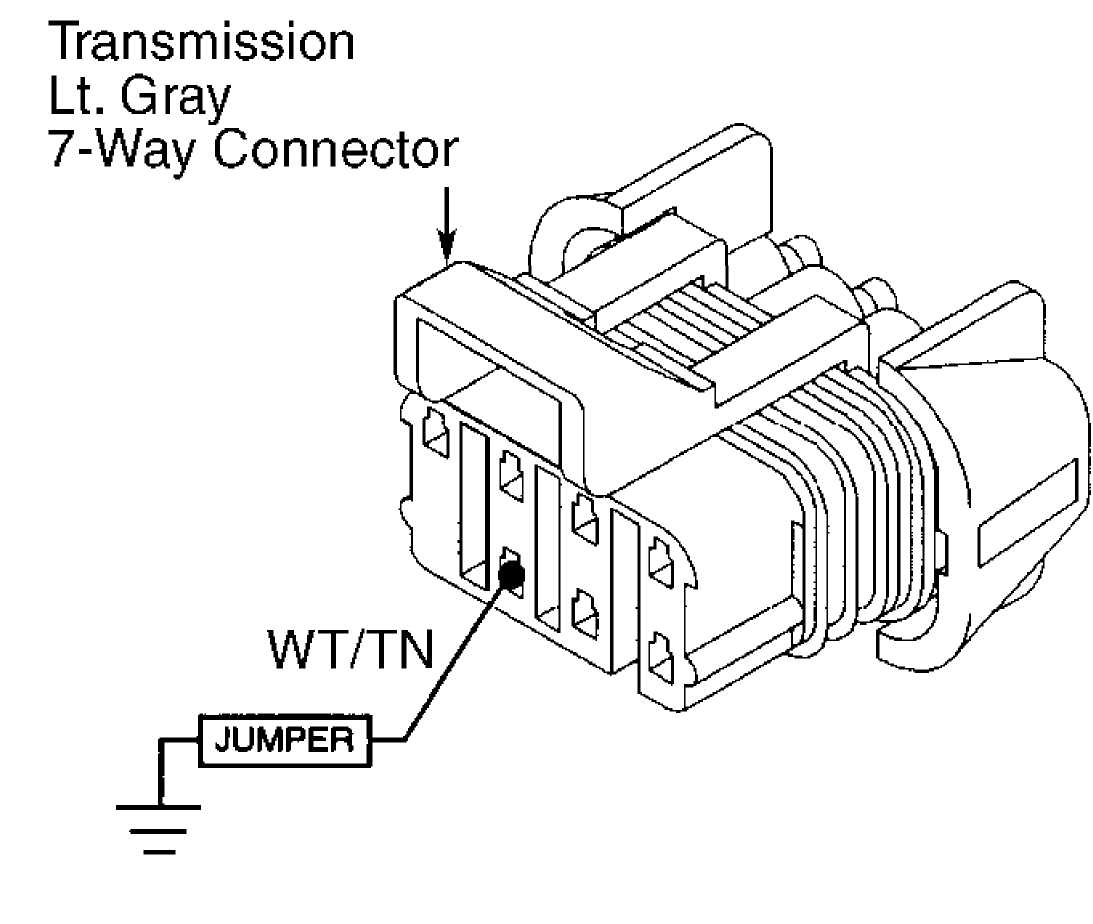
Fig. 52: Test 5A - Transmission 7-Way Connector (Female Side)

WT/TN
92114256
Fig. 53: Test 5A - Code 702, View of Speed Sensor Connector
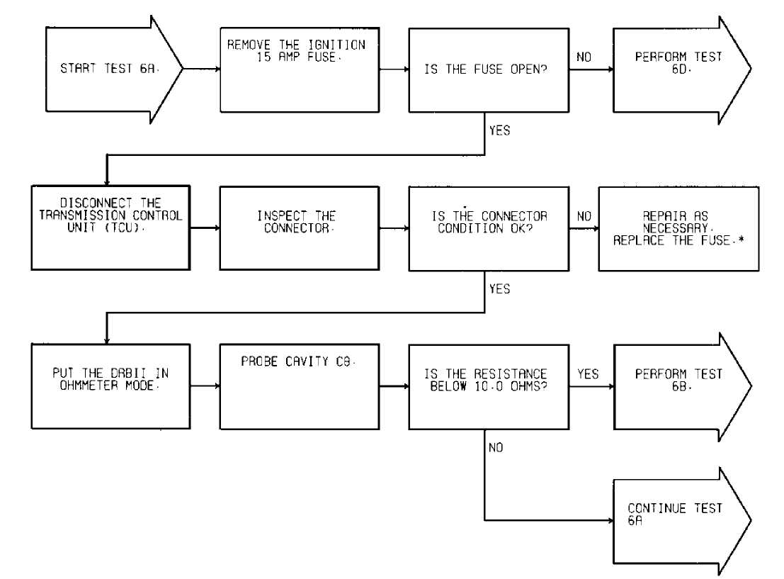
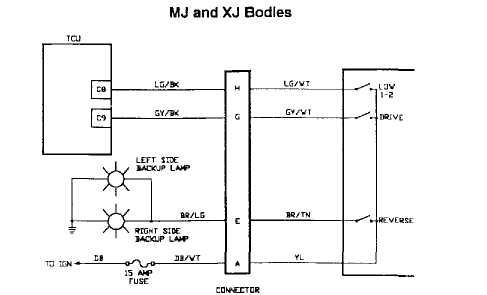
TEST 6A - CODE 703 - GEAR SELECT SWITCH CIRCUIT
Perform TEST 1A before proceeding.
 92 ąø 4257 "-PERFORM VERIFICATION TEST 2A.
Fig. 54: Test 6A - Code 703, Flow Chart (1 of 2) MJ and XJ Bodies
FUSE fl-U*Y GEAR SELECT
92ąö14258 ąĪą¤ą¢ąĪąóą¤!
Fig. 55: Test 6A - Gear Select Switch Schematic (Cherokee)
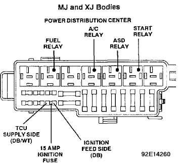
Fig. 56: Test 6A - Location of Gear Select Switch Fuse (Cherokee)
ZJ Body: I_G 92G14262
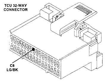
Fig. 57: Test 6A - TCU 32-Way Connector (Cavity 8)
92H14263
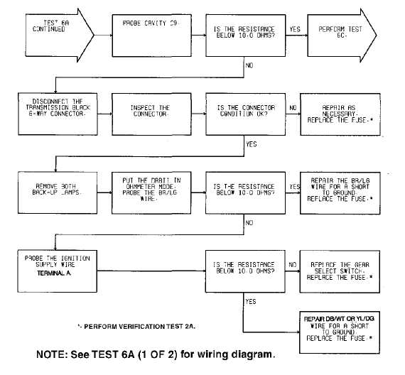
Fig. 58: Test 6A - Code 703, Flow Chart (2 of 2)
MJ and XJ Bodies
B-U┬╗V GEAR SELLCT
92 A14258 ą┐ą╗ą╝ą│ą┐ąĖ
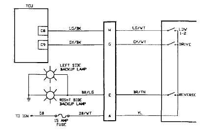
Fig. 59: Test 6A - Gear Select Switch Schematic (Cherokee)
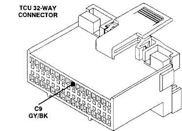
ZJ Body: DQ
Fig. 60: Test 6A
- Code 703, TCU 32-Way Connector (Cavity 9)
 Transmission
Lt. Gray
92F13594
7-Way Connector
Fig. 61: Test 6A - Code 703, Location of Gear Select Switch
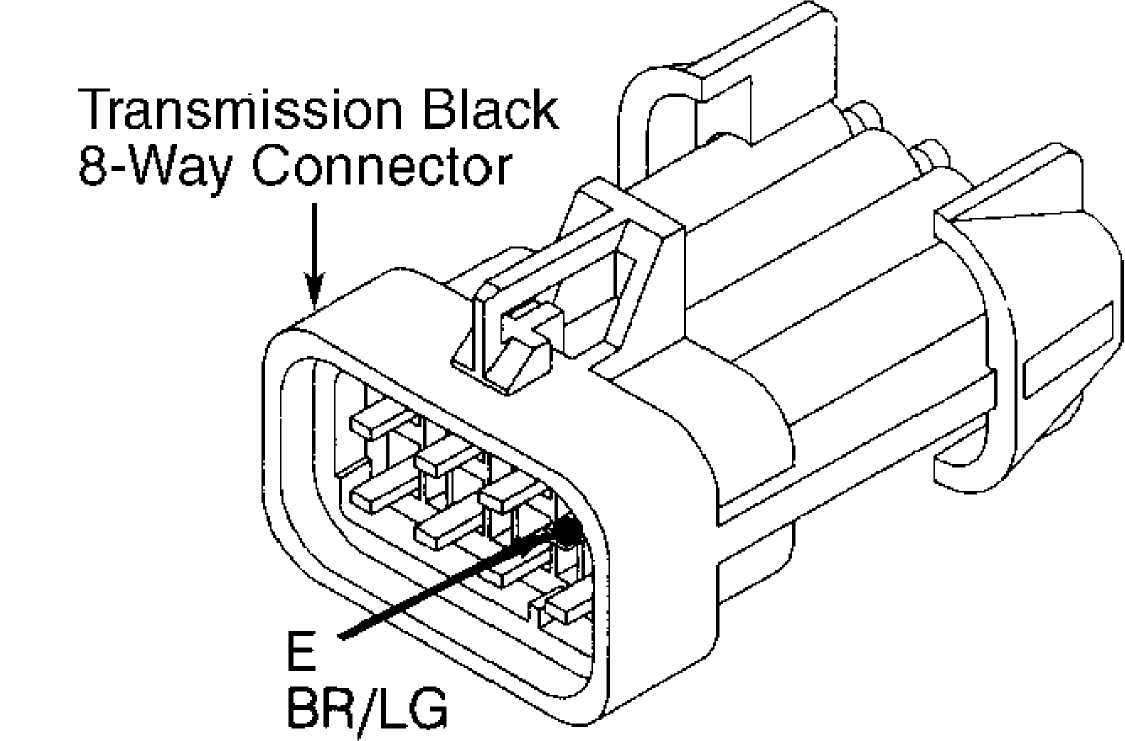
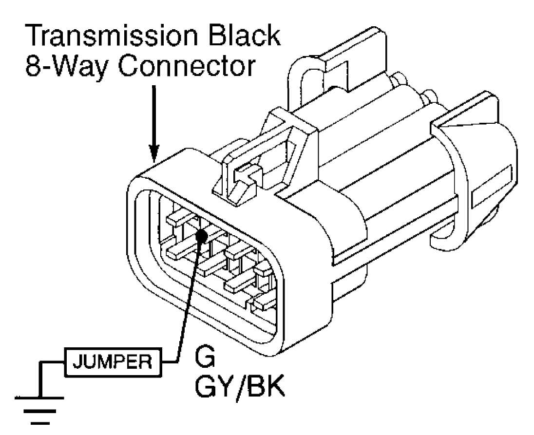
92J14265
Fig. 62: Test 6A - Code 703,
XJ BODY
8-Way Black Connector Cavity "E"
ąŁ2ąÉ14266
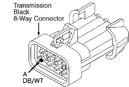
Fig. 63: Test 6A - 8-Way Black Connector Cavity "A" (Cherokee)
TEST 6B - CODE 703 - GEAR SELECT SWITCH CIRCUIT
NOTE: Perform TEST 6A - CODE 703 - GEAR SELECT SWITCH CIRCUIT
before proceeding.
Perform TEST 6A before proceeding.

ąŁ2ąĪ14268
Fig. 64: Test 6B - Code 703, Flow Chart
MJ and XJ Bodies
B-U┬╗V GEAR SELLCT
92 A14258 ą┐ą╗ą╝ą│ą┐ąĖ
Fig. 65: Test 6B - Gear Select Switch Schematic (Cherokee)

92F13594
Fig. 66: Test 6B - Code 703, Location of Gear Select Switch
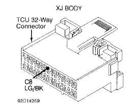
Fig. 67: Test 6B - TCU 32-Way Connector (Cavity 8, Cherokee)
TEST 6C - CODE 703 - GEAR SELECT SWITCH CIRCUIT
NOTE: Perform TEST 6A - CODE 703 - GEAR SELECT SWITCH CIRCUIT before proceeding.
Perform TEST 6A before proceeding.
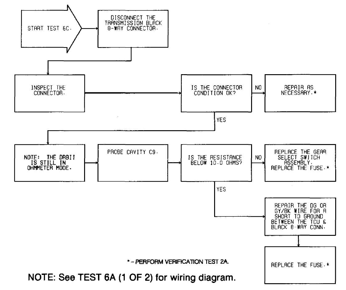
ąŁ2ąØ14271
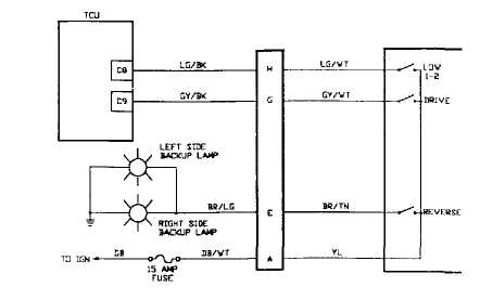
Fig. 68: Test 6C - Code 703, Flow Chart
MJ and XJ Bodies
|
LG/WT |
||
|
1-2 |
||
|
GV/VT |
-^ |
DRIVE |
|
ą▓čć/čéąĮ |
REVERSE |
|
B-U┬╗V GEAR SELLCT
92 A14258 ą┐ą╗ą╝ą│ą┐ąĖ
Fig. 69: Test 6C - Gear Select Switch Schematic (Cherokee)
92F13594
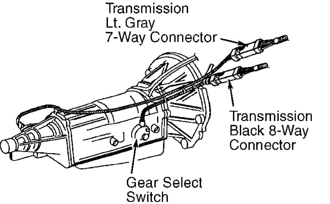
Fig. 70: Test 6C - Code 703, Location of Gear Select Switch
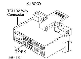
Fig. 71: Test 6C - TCU 32-Way Connector (Cavity 9, Cherokee)
TEST 6D - CODE 703 - GEAR SELECT SWITCH CIRCUIT
NOTE:
Perform TEST 6A - CODE 703 - GEAR SELECT SWITCH CIRCUIT before proceeding.
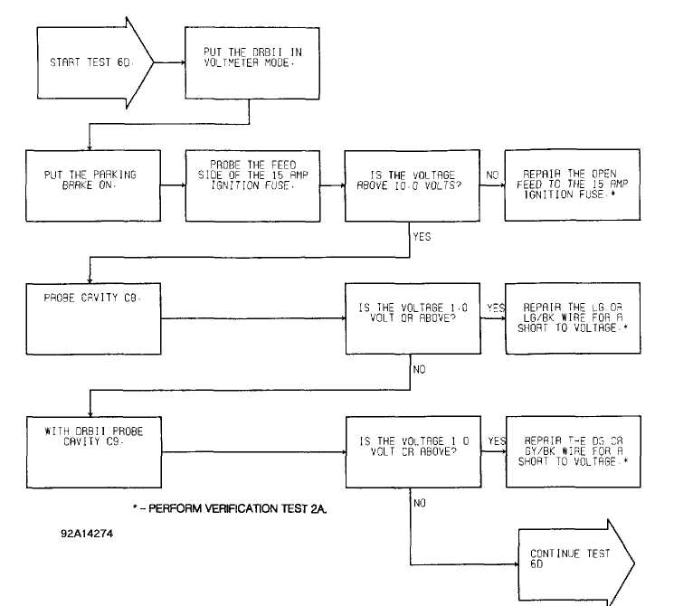
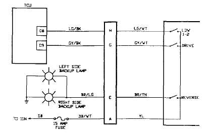
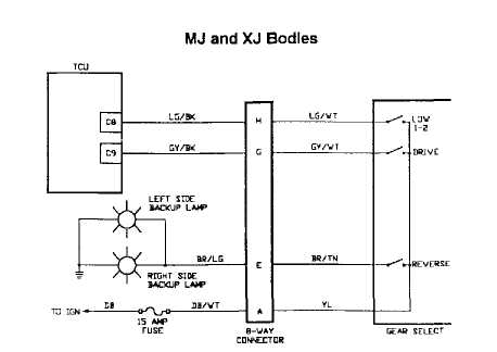
Fig. 72: Test 6D - Code 703, Flow Chart (1 of 3) MJ and XJ Bodies
B-W┬╗y GEAR SELLCT
92 A14258 ą┐ą╗ą╝ą│čéą░
Fig. 73: Test 6D - Gear Select Switch Schematic (Cherokee)
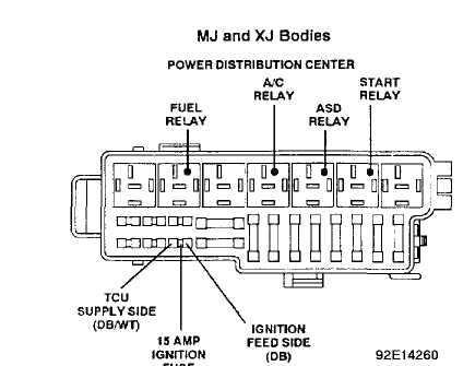
Fig. 74: Test 6D - Location of Gear Select Switch Fuse (Cherokee)
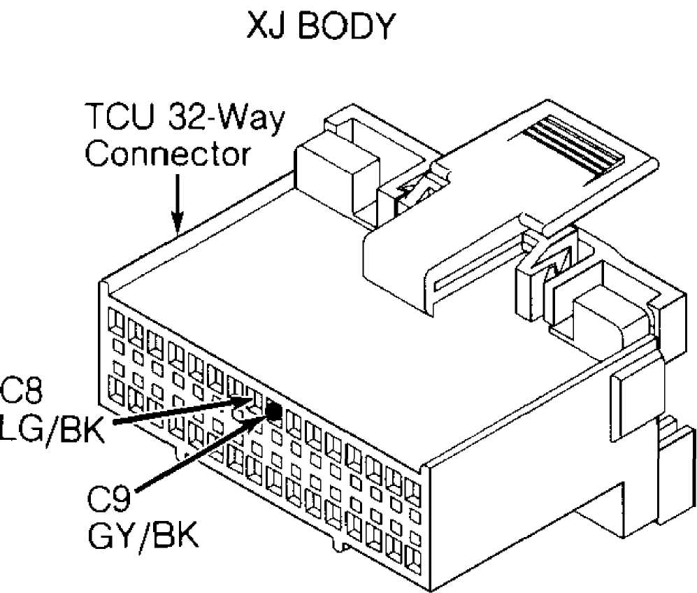
ąŁ2ąÆ14275
Fig. 75: Test 6D - TCU 32-Way Connector (Cavities 8 & 9, Cherokee)
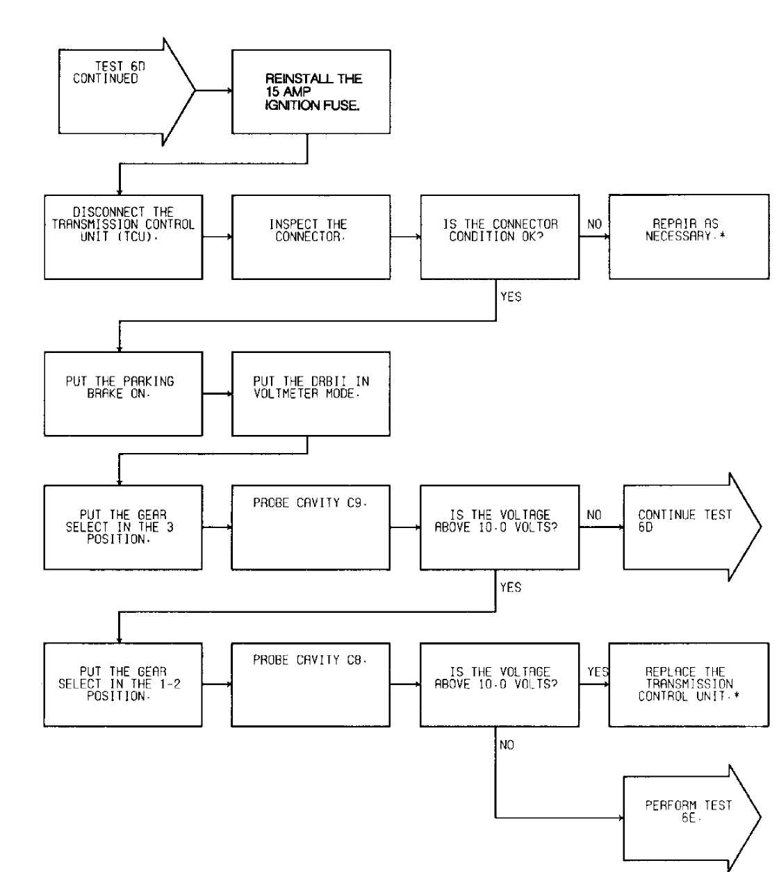
92D14277 *-PERFORM VERIFfCATlON TEST 2A.
Fig. 76: Test 6D - Code 703, Flow Chart (2 of 3)
92 A14258
Fig. 77: Test 6D - Gear Select Switch Schematic (Cherokee)
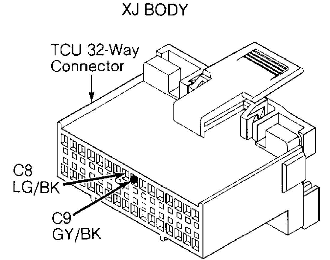
92B14275
Fig. 78: Test 6D - TCU 32-Way Connector (Cavities 8 & 9, Cherokee)
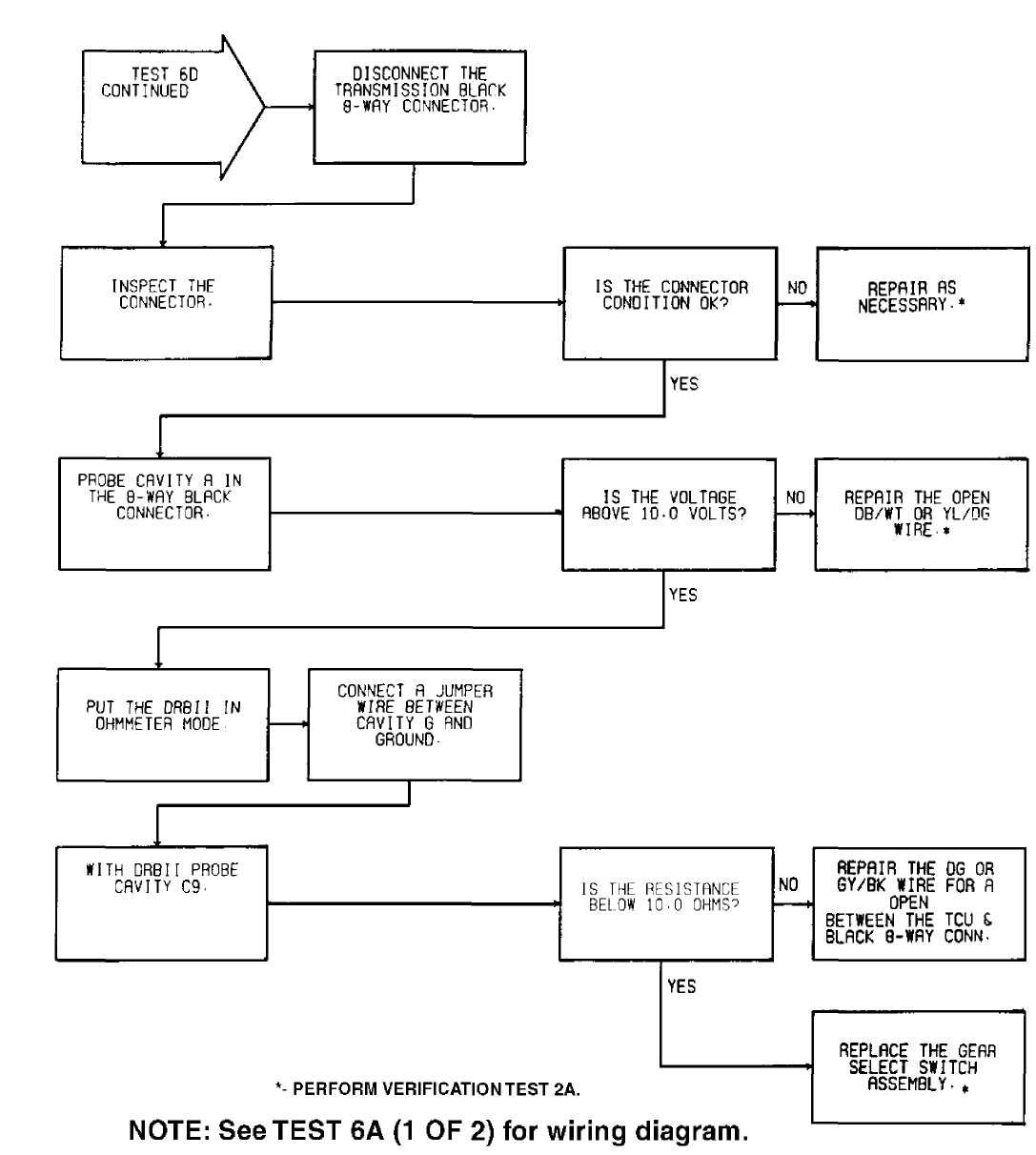
ąŁ2ąĢ14278
Fig. 79: Test 6D - Code 703, Flow Chart (3 of 3)
92 A14258
Fig. 80: Test 6D - Gear Select Switch Schematic (Cherokee)
92F13594
Fig. 81: Test 6D - Code 703, Location of Gear Select Switch

ąŁ2ąÉ14266
Fig. 82: Test 6D - 8-Way Black Connector Cavity "A" (Cherokee)
XJ BODY
92F14279
Fig. 83: Test 6D - 8-Way Black Connector Cavity "G" (Cherokee)
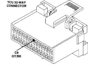
ZJ Body: DG 92114264
Fig. 84: Test 6D - Code 703, TCU 32-Way Connector (Cavity 9)
TEST 6E - CODE 703 - GEAR SELECT SWITCH CIRCUIT
NOTE: Perform TEST 6D - CODE 703 - GEAR SELECT SWITCH CIRCUIT before proceeding.
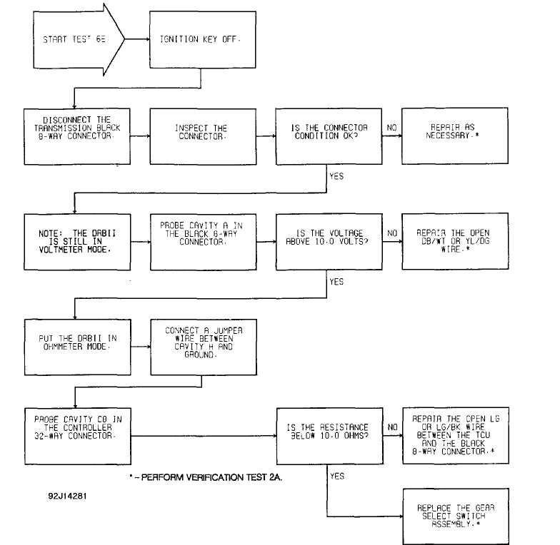
Fig. 85: Test 6E - Code 703, Flow Chart
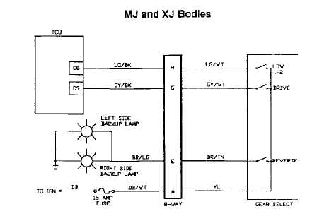
92 A14258 ą┐ą╗ą╝ą│ą┐ąĖ
Fig. 86: Test 6E - Gear Select Switch Schematic (Cherokee)
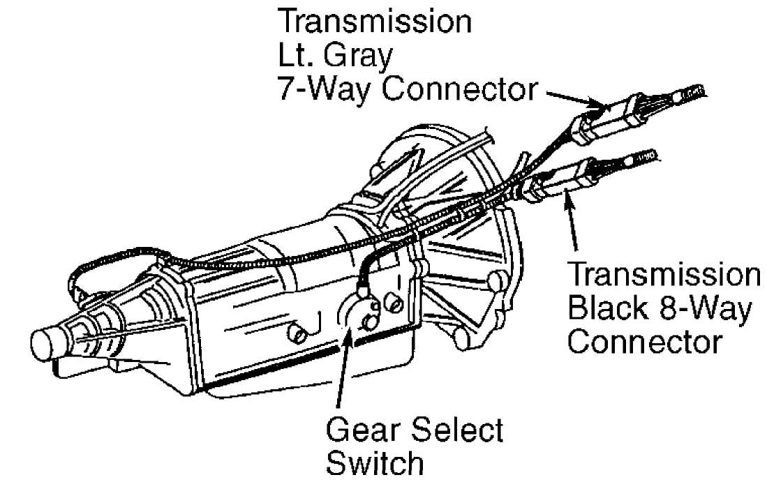
92F13594
Fig. 87: Test 6E - Code 703, Location of Gear Select Switch
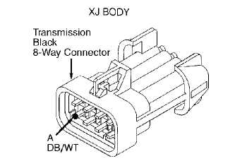
ąŁ2ąÉ14266
Fig. 88: Test 6E - 8-Way Black Connector Cavity "A" (Cherokee)
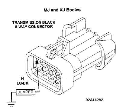 Fig.
Fig.
9: Test 6E - 8-Way Black Connector Cavity "H" (Cherokee)
ZJ Body: LG 92G14262
Fig. 90: Test 6E - TCU 32-Way Connector (Cavity
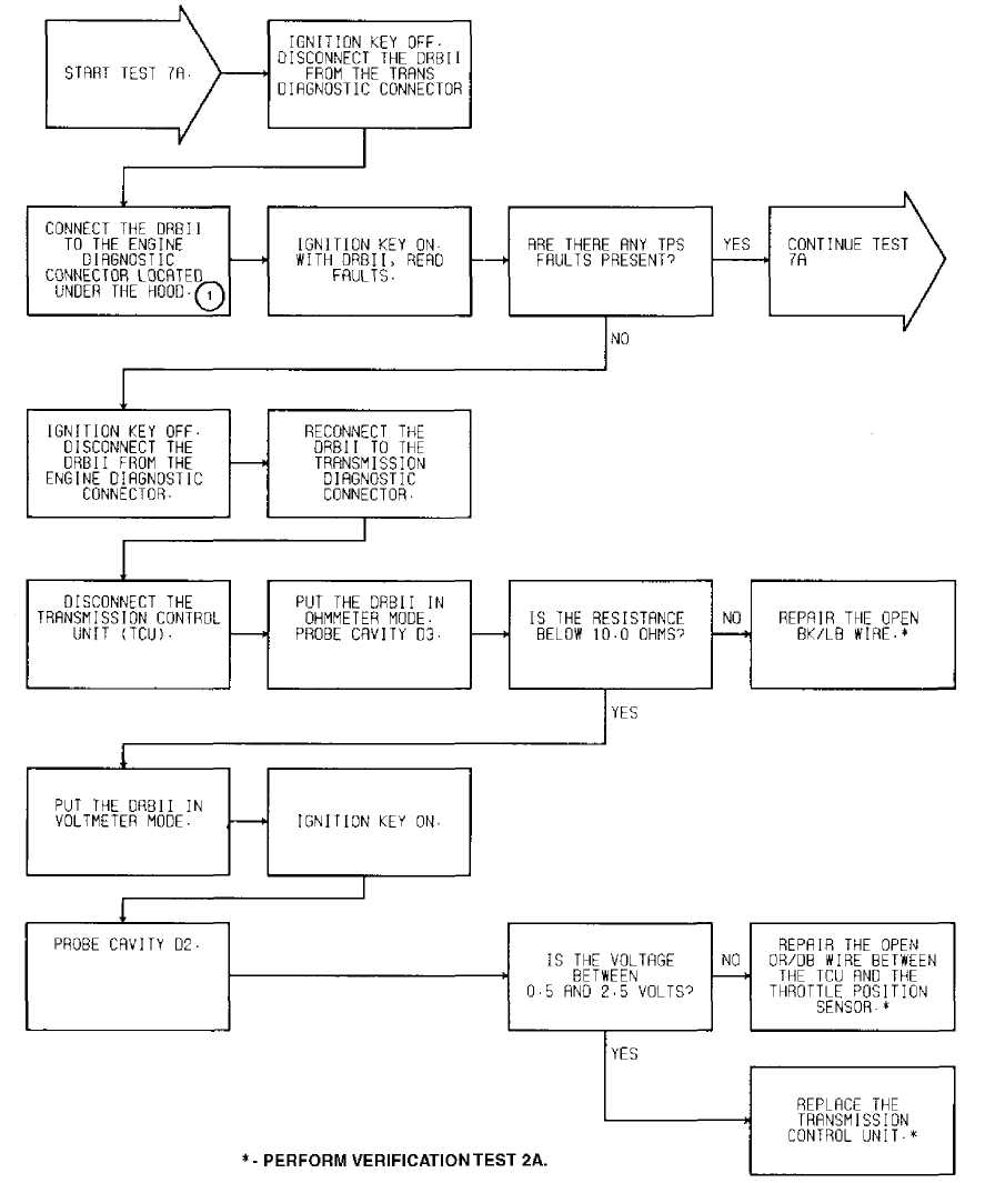
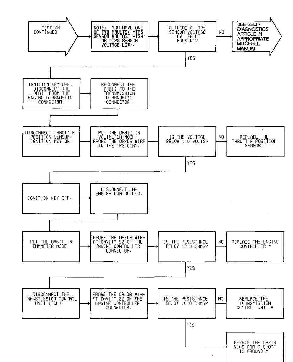
TEST 7A - CODE 705 - TPS CIRCUIT
NOTE: Perform TEST 1A - VERIFICATION OF THE COMPLAINT before proceeding.
NOTE: On Cherokee, engine diagnostic connector is located at left side of engine compartment, near engine controller. Engine diagnostic connector is a 6-terminal connector.
Perform TEST 6D before proceeding.
┬® - On XJ models, engine diagnostic connector is located at left side of engine compartment, near engine controller.
94138438
Fig. 91: Test 7A - Code 705, Flow Chart (1 of 2)
ENGINE CONTROLLER

Fig. 92: Test 7A - Code 705, Schematic
 92E142S6
Fig. 93: Test 7A - TCU 32-Way Connector (Cavities D2 & D3)
 ŌĆó - PERFORM VERIFICATION TEST 2A.
NOTE: See TEST 7A {1 OF 2) for wiring diagram.
92F14287
Fig. 94: Test 7A - Code 705, Flow Chart (2 of 2)
ENGINE CONTROLLER
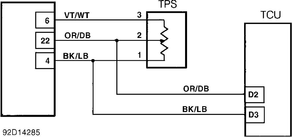
Fig. 95: Test 7A - Code 705, Schematic
AIS Motor
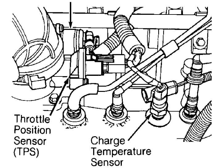
92G14288
Fig. 96: Test 7A - Location of Throttle Position Sensor (TPS)
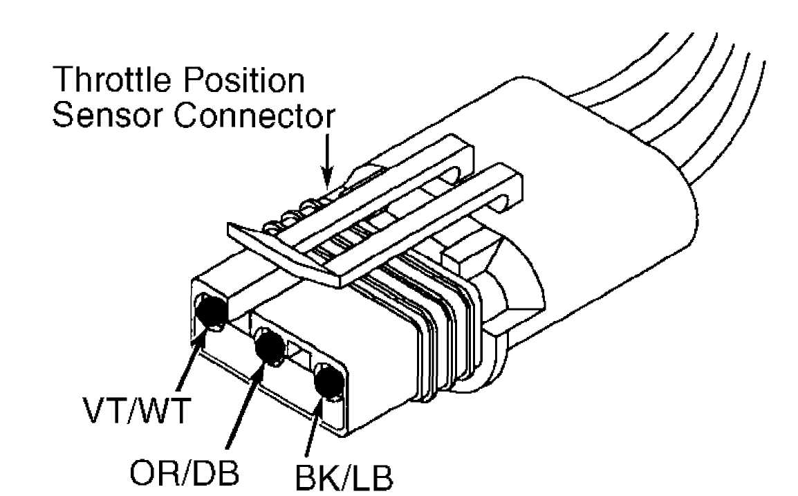
92H14289
Fig. 97: Test 7A - Code 705, View of TPS Connector
92A14290
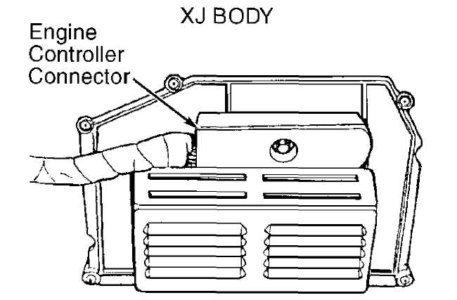
Fig. 98: Test 7A - Location of Engine Control Connector (Cherokee)
Engine
Controller
Connector
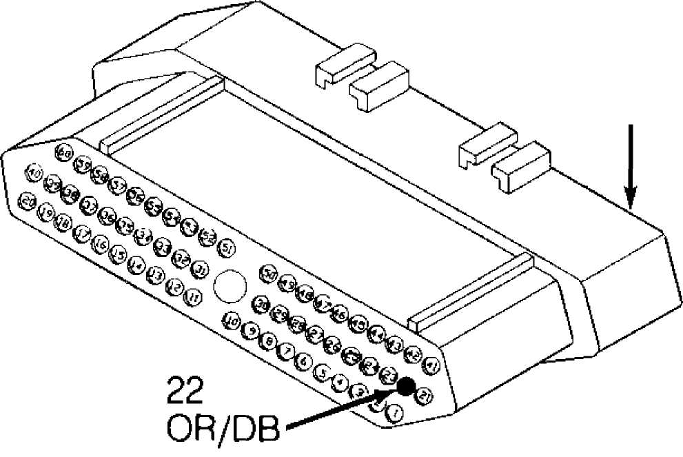
92C14292
Fig. 99: Test 7A - View of Engine Control Connector (Cavity 22)
TEST 8A - CODE 706 - BRAKE SWITCH CIRCUIT
NOTE: Perform TEST 1A - VERIFICATION OF THE COMPLAINT before proceeding.
Perform TEST 1A before proceeding.
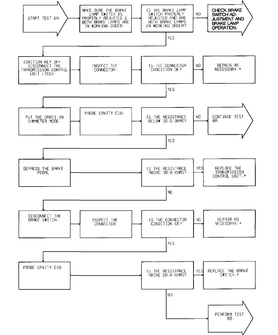
92D14293 *" PERF0RM VERIFICATION TEST 2A.
Fig. 100: Test 8A - Code 706, Flow Chart
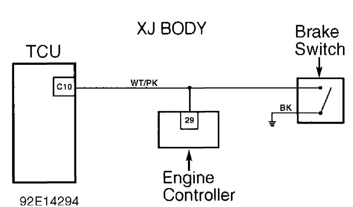
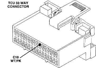
Fig. 101: Test 8A - Code 706, Schematic (Cherokee)
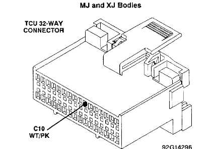
Fig. 102: Test 8A - TCU 32-Way Connector (Cavity 10, Cherokee)
 ąŁ2ąĪ13583
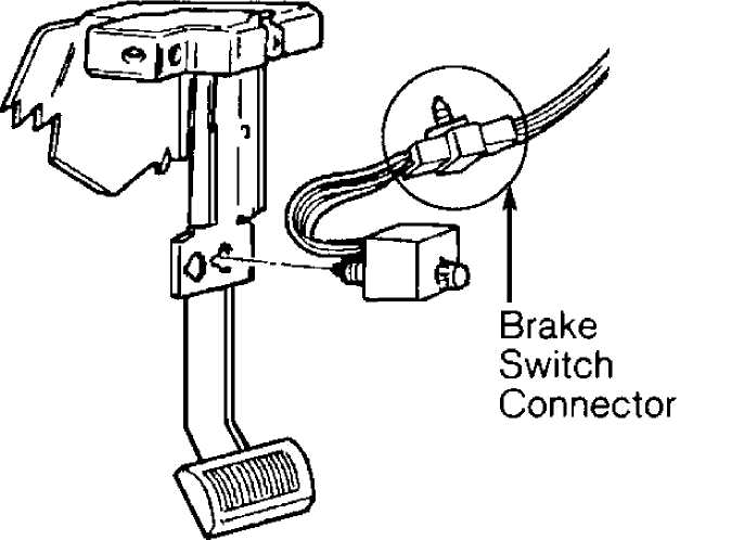
Fig. 103: Test 8A
- Location of Brake Switch Connector
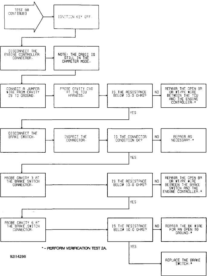
Fig. 104: Test 8A - Code 706, Flow Chart

XJ BODY TCU
92E14294
Fig. 105: Test 8A
Engine Controller
Code 706, Schematic (Cherokee)
MJ and XJ Bodies ENGINE CONTROLLER CONNECTOR
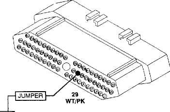
ZJ Body: BR
92J14299
Fig. 106: Test 8A - View of Engine Controller Connector (Cavity 29)
MJ and XJ Bodies
92G14296
Fig. 107: Test 8A - TCU 32-Way Connector (Cavity 10, Cherokee)
92C13583
Fig. 108: Test 8A - Location of Brake Switch Connector
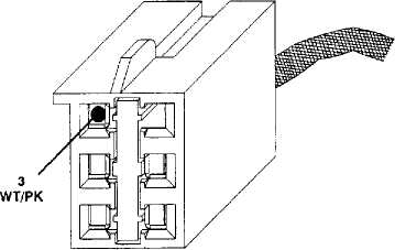
BRAKE SWITCH CONNECTOR
ZJBody: BR
Fig. 109: Test 8A - View of Brake Switch Connector (Cavity 3)
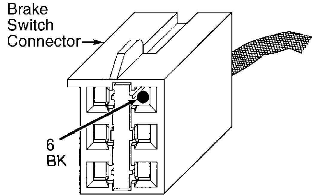
92D14301
Fig. 110: Test 8A - View of Brake Switch Connector (Cavity 6)
TEST 8B - CODE 706 - BRAKE SWITCH CIRCUIT
NOTE: Perform TEST 8A - CODE 706 - BRAKE SWITCH CIRCUIT before proceeding.
Perform TEST 8A before proceeding.