Ā
1993 Jeep Cherokee
1993 ACCESSORIES & EQUIPMENT Chrysler Corp. Instrument Panels
Jeep; Cherokee
DESCRIPTION
Instrument panel is supplied voltage through gauges fuse. A printed circuit on rear of instrument cluster distributes voltage to gauges and indicators.
Emission Maintenance Timer
Emission Maintenance Timer and Indicator Light activate when mileage reaches scheduled maintenance interval of 82,500 miles. Timer can be reset using DRB-II.
TESTING
GAUGE TESTING
Compare resistance values of malfunctioning gauge to specifications. See OIL PRESSURE GAUGE RESISTANCE, FUEL GAUGE RESISTANCE and TEMPERATURE GAUGE RESISTANCE tables.
OIL PRESSURE GAUGE RESISTANCE TABLE
Oil Pressure (psi) Ohms
0 1
40 46
80 87
FUEL GAUGE RESISTANCE TABLE
Application Ohms
Empty 105
1/2 Full 33
Full 5
TEMPERATURE GAUGE RESISTANCE TABLE
Application & Test Temperature Ohms
100F (38C) 1365.0
220F (104C) 93.5
260F (127C) 55.1
BRAKE INDICATOR INOPERATIVE
1) Turn ignition switch on with engine off. Apply parking brake, and unplug brake warning light switch connector. Connector is located below brake master cylinder at left rear of engine compartment. Jumper between brake warning light switch connector Gray/White wire and ground. If bulb is good and indicator lights,
repair open circuit to indicator.
2) With ignition switch off, measure resistance between brake warning switch connector Gray wire (changes to Gray/White wire at splice) and ground. If reading is zero ohms, check switch and/or brake system. If reading is not zero ohms, repair open circuit to parking brake switch ground.
COOLANT TEMPERATURE GAUGE INOPERATIVE
Turn ignition switch on with engine off. Disconnect coolant temperature sending unit connector (located at left rear of engine). If needle does not indicate at low end of scale, touch connector Violet/Yellow wire to ground. If needle indicates at high end of scale, replace sending unit. If needle does not indicate at high end of scale, repair open Violet/Yellow wire to gauge.
COOLANT TEMPERATURE INDICATOR LIGHT INOPERATIVE
Turn ignition switch on with engine off. Disconnect coolant temperature sender connector (located at left rear of engine). Touch connector Violet/Yellow wire to ground. If indicator lights, replace switch. If bulb is good and indicator light remains off, repair open Violet/Yellow wire to instrument cluster terminal.
FUEL GAUGE INOPERATIVE
With ignition on and engine off, disconnect fuel gauge sending unit connector. If needle goes to "E", replace sending unit. If needle does not go to "E", connect fuel gauge sending unit connector and disconnect instrument cluster connector terminal B1. Check resistance of sending unit. If resistance is 5-105 ohms, replace gauge. If resistance is not 5-105 ohms, repair open Dark Blue wire to sending unit.
GAUGES & INDICATORS INOPERATIVE
Check gauge fuses. Replace if blown. Test instrument cluster connector terminal A3 ground wire. See Figs. 1 and 2. If any resistance to ground is detected, repair open Black wire in ground circuit.
PANEL LIGHTS: ALL LIGHTS INOPERATIVE, PARKING LIGHTS WORKING
Check PARK fuse and instrument lights fuse. Replace if
necessary. Repair short to ground in 12-volt supply wire to blown
fuse.
Using voltmeter, probe battery side of instrument lights
fuse while turning headlight switch dimming rheostat from LO to HI. If
results are not zero volts for LO and battery voltage for HI, replace
headlight switch.
Using DVOM, check resistance at ground (bulb) side of
instrument lights fuse with parking lights off. If resistance to
ground is almost zero (allowing for bulb filaments), system is good.
If resistance is zero ohms, 12-volt supply wire from fuse is shorted
to ground. Repair short.
LOW FUEL WARNING LIGHT INOPERATIVE
Turn ignition on with engine off. Disconnect wire to terminal B1 of instrument cluster connector. See Figs. 1 and 2. Wait 10 seconds. If indicator light glows, system is good. Replace sending unit. If indicator light does not glow, replace low fuel warning
module (on back of instrument cluster). OIL PRESSURE GAUGE INOPERATIVE
Turn ignition on with engine off. Disconnect oil pressure
sender connector, located on right side of engine, next to
distributor. If needle goes to high indication, system is good.
If needle does not indicate at high end of scale, touch
oil pressure sending unit connector Gray wire to ground. If needle
indicates at low end of scale, replace sending unit. If needle does
not indicate at low end of scale, repair open in Gray wire circuit to
gauge (instrument cluster terminal B7). See Figs. 1 and 2.
OIL PRESSURE INDICATOR INOPERATIVE
Turn ignition on with engine off. Touch oil pressure switch connector Gray wire to ground. If light glows, replace switch. If light does not glow and bulb is good, repair open in Gray wire to instrument cluster connector terminal B7. See Figs. 1 and 2.
PART TIME OR 4WD INDICATOR INOPERATIVE
Apply parking brake. Start engine. Place 4WD selector
lever in 4WD LOCK or 4WD position. Unplug 4WD switch, and touch
harness connector Black/Yellow wire to ground. If indicator light
glows, wiring system is good. Check 4WD switch operation, and replace
switch if defective.
If indicator light does not glow and bulb is good, repair
open in Black/Yellow wire circuit to indicator light.
TACHOMETER INOPERATIVE
Tachometer input is from engine PCM pin No. 43. Check
Gray/Light Blue wire for short or open circuits. If wire is okay, see appropriate G - TESTS W/CODES article in the ENGINE PERFORMANCE Section.
VOLTMETER (GAUGE) INOPERATIVE
Turn ignition on with engine off. If voltmeter does not indicate battery voltage, check voltage at instrument cluster connector terminal A8. See Figs. 1 and 2. If battery voltage exists at terminal A8, replace voltmeter. If battery voltage does not exist at terminal A8, repair open White/Black wire circuit to gauges fuse.

|
NO. |
LAMP |
TERMINAL NAME |
|
1 |
A |
.OW WASHER |
|
2 |
ąÆ |
:heck engine |
|
ąÆ |
GN |
|
|
4 |
^ *" |
GN |
|
S |
^ |
GN |
|
6 |
ąĪ |
CHECK ANTILOCK |
|
7 |
D |
UP SHIFT |
|
┬╗ |
E |
MAKE |
|
9 |
F |
SECURITY |
|
10 |
F |
SAH |
|
11 |
G |
=ULL TIME |
|
12 |
H |
>ART TIME |
|
13 |
1 |
MAINT REQD |
|
14 |
1 |
GN |
|
15 |
J |
SEAT BELT |
|
16 |
^--^ |
3ND |
Fig. 1: Instrument Cluster Connector ID & Location Courtesy of Chrysler Corp.
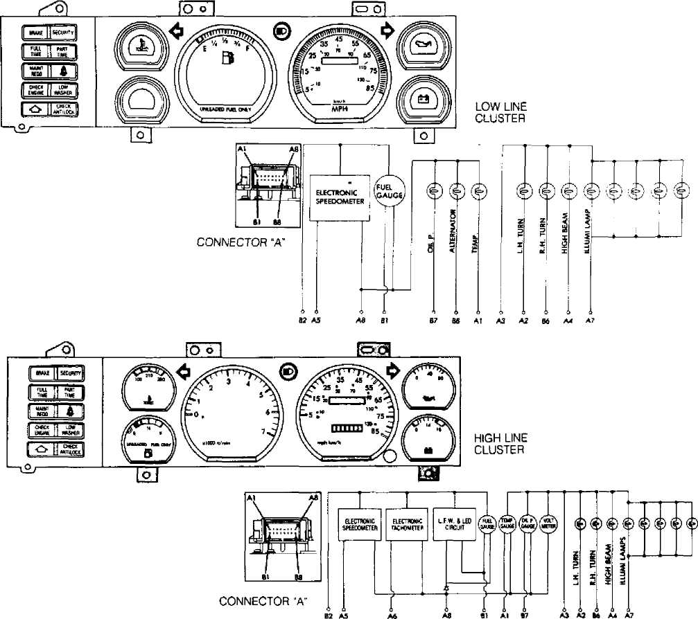
91C14466
Fig. 2: Instrument Cluster Connector Terminal ID Courtesy of Chrysler Corp.
REMOVAL & INSTALLATION
INSTRUMENT CLUSTER
Removal & Installation
Disconnect negative battery cable. Remove 4 instrument
cluster bezel attaching screws, and unsnap instrument cluster bezel.
See Fig. 3. Remove cigarette lighter housing attaching screw. Remove
switch housing attaching screws. See Fig. 4.
Remove instrument cluster attaching screws. Pull out
cluster assembly far enough to disconnect 2 multiple plugs, and remove
instrument cluster. See Figs. 5 and 6. To install, reverse removal
procedure.
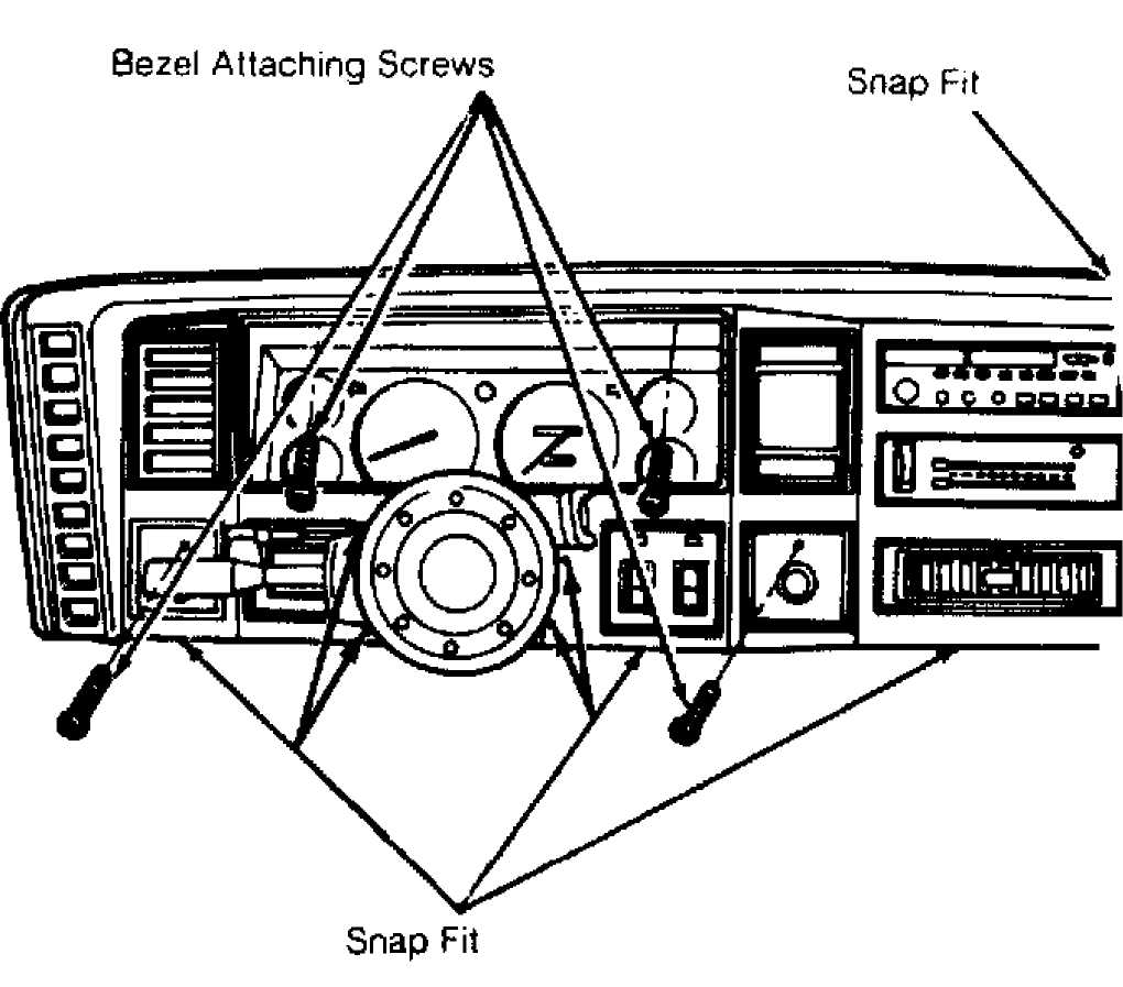
Fig. 3: Removing Instrument Cluster Bezel Courtesy of Chrysler Corp.
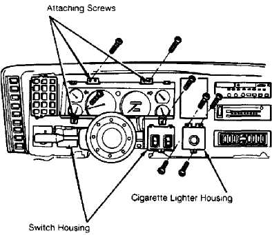
Fig. 4: Removing Instrument Cluster Courtesy of Chrysler Corp.
13
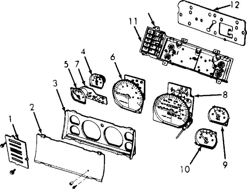
Tell-Tale Display
Lens
Gauge Bezel
Temperature Gauge
Fuel Gauge
Tachometer
Low Fuel Warning Module
Speedometer
Oil Pressure Gauge
Voltmeter
Mounting Bezel
Printed Circuit (Gauges)
Printed Circuit (Tell-Tale)
Fig. 5: Exploded View Of Instrument Cluster Courtesy of Chrysler Corp.
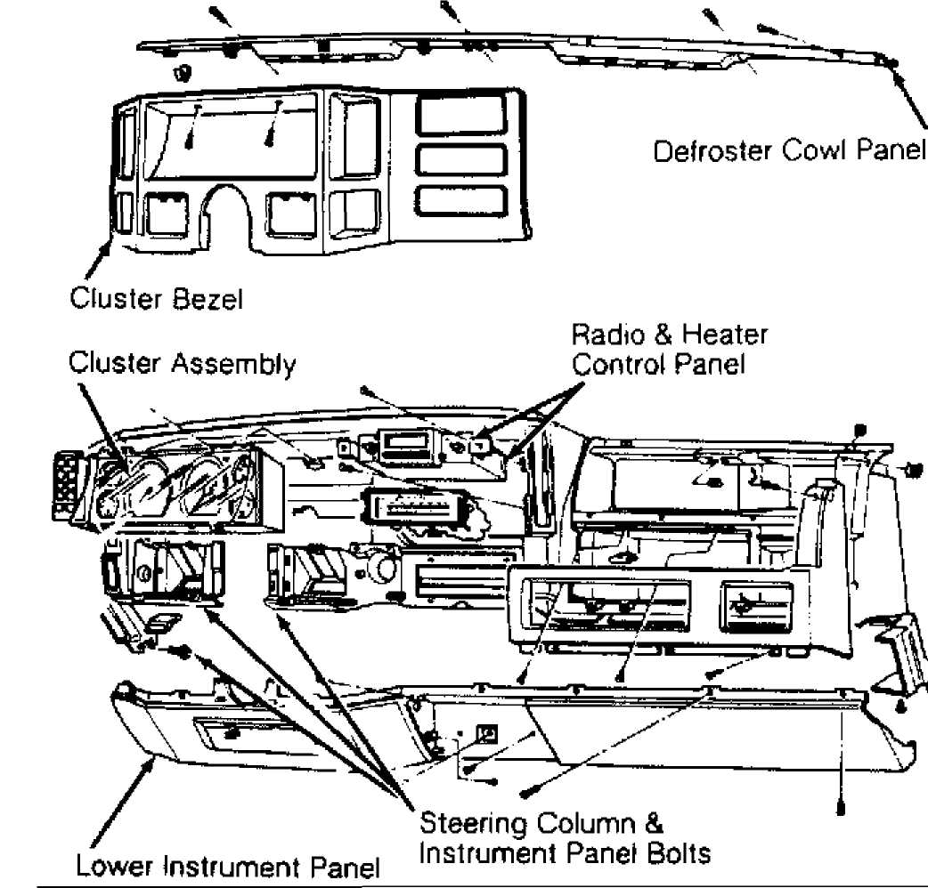
Fig. 6: Exploded View Of Instrument Panel Courtesy of Chrysler Corp.
WIRING DIAGRAMS
See appropriate chassis wiring diagram in WIRING DIAGRAMS.