Ā
1993 Jeep Cherokee
1993 BRAKES
Chrysler Corp. - Disc & Drum
Jeep; Cherokee, Grand Cherokee, Grand Wagoneer, Wrangler
DESCRIPTION
Floating caliper disc brake assembly uses a single piston caliper which floats on 2 bolts. As brake pedal is depressed, hydraulic pressure passes through a proportioning valve to brake caliper piston.
This force is transmitted to inboard brake pad, forcing it against braking surface of rotor. Pressure then moves outer caliper housing and pad inward on caliper mounting bolts, forcing outer pad against outer braking surface of rotor.
A combination proportioning valve/pressure differential switch is used on all models. Proportioning valve is not serviceable. Valve must be replaced if it malfunctions.
A pressure differential brake warning light switch is used to warn vehicle operator that one side of the hydraulic system has failed. When hydraulic pressure is equal in both front and rear systems, switch piston remains centered and does not contact terminal in switch. If one side of brake system fails, hydraulic pressure moves piston toward failed side. Shoulder of piston contacts switch terminal, grounding brake warning light.
Proportioning valve operates by restricting hydraulic pressure to rear brakes at a given ratio when system hydraulic pressure reaches a certain point. This improves front-to-rear brake balance during high speed braking, when a percentage of rear weight is transferred to front wheels. Valve reduces rear brake pressure and delays rear wheel skid. On light brake application, valve allows full hydraulic pressure to rear brakes.
BLEEDING BRAKE SYSTEM
NOTE: Brake bleeding procedures for models with anti-lock brakes are not covered in this article. See ANTI-LOCK BRAKE SYSTEM article for proper procedure.
BLEEDING SEQUENCE
Before bleeding system, exhaust all vacuum from power unit by depressing brake pedal several times. When bleeding disc brakes, air may tend to cling to caliper walls. To aid in removal of air, lightly tap caliper while bleeding.
Fill master cylinder with clean brake fluid. Fluid should meet DOT 3 specifications. Bleed master cylinder with bleeder valves (if equipped). Bleed wheel cylinders and calipers in sequence. See BRAKELINE BLEEDING SEQUENCE table.
BRAKELINE BLEEDING SEQUENCE TABLE
Application Sequence
All Models RR, LR, RF, LF
MASTER CYLINDER BLEEDING
Bench Bleeding
Master cylinder must be bled before installation to
prevent excessive amounts of air from entering hydraulic system,
creating poor brake operation.
Place master cylinder in soft-jawed vise. DO NOT tighten
vise enough to damage master cylinder. Install bleed tubes in both
outlets of master cylinder. See Fig. 1.
Fill master cylinder with clean brake fluid. Fluid should
meet DOT 3 specifications. Ensure end of bleed tubes are submerged in
brake fluid.
Using proper size rod, apply and release master cylinder
until no air bubbles exist in brake fluid flow. When all air bubbles
are gone from master cylinder, cap outlet ports. Install reservoir
cover and seal. Install master cylinder and bleed on vehicle.
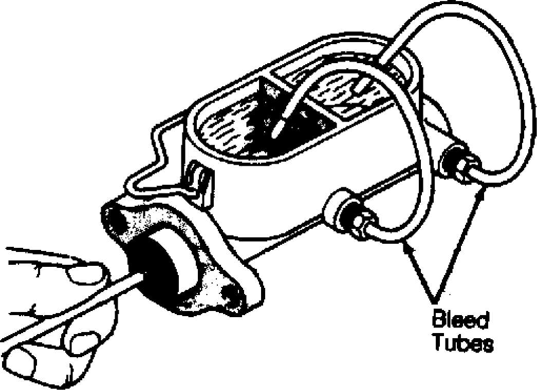
Fig. 1: Bleeding Master Cylinder (Typical) Courtesy of Chrysler Motors.
On-Vehicle Bleeding
Install master cylinder on vehicle after bench bleeding.
Remove bleeder lines and install brakelines. DO NOT tighten brakelines
yet.
Slowly force brake pedal to floor and hold in this
position. Tighten brakelines, and release brake pedal. Repeat
procedure until no air bubbles exist at brakelines. Tighten
brakelines. Check for leaks. PRESSURE BLEEDING
CAUTION: Front brake metering valve is located in front end of
combination valve. Valve stem MUST be pressed inward or held outward slightly to bleed front brakes.
Clean master cylinder cap and surrounding area. Remove
cap. With pressure tank at least 1/2 full, connect to master cylinder
with adapters. Attach bleed hose to first bleeder valve to be
serviced. See BRAKELINE BLEEDING SEQUENCE table under BLEEDING
SEQUENCE.
Place other end of hose in clean glass jar partially
filled with clean brake fluid so end of hose is submerged in fluid.
Open release valve on pressure bleeder. Follow equipment
manufacturerÆs pressure instructions or see PRESSURE BLEEDER SETTINGS
table. Open bleeder valve 3/4 turn, and note fluid flow.
Close bleeder screw when fluid is free of bubbles. Repeat
procedure on remaining wheels in proper sequence. Check brake pedal
operation after bleeding has been completed.
Remove pressure bleeding equipment and valve retainer from
hold-off valve. Ensure master cylinder is full of fluid. Check for
leaks.
PRESSURE BLEEDER SETTINGS TABLE
Application psi (kg/cm2)
All Models 15-20 (1.1-1.4)
MANUAL BLEEDING
NOTE: Some models are equipped with anti-lock brake system. See ANTI-LOCK BRAKE SYSTEM article for bleeding procedure.
Cherokee & Wrangler
Fill master cylinder with clean brake fluid. Fluid should
meet DOT 3 specifications. Open ALL bleed valves. Close bleeder valves
when fluid begins flowing from each valve. Refill master cylinder.
Install bleed hose to first bleeder valve to be serviced.
See BRAKELINE BLEEDING SEQUENCE table under BLEEDING SEQUENCE.
Submerge other end of hose in clean glass jar partially filled with
clean brake fluid. See Fig. 2.
NOTE: Ensure bleeder valve is closed when brake pedal is released. DO NOT allow master cylinder to run out of fluid.
3) Open bleeder valve 3/4 turn. Depress brake pedal slowly
through full travel. Close bleeder valve, and release pedal. Repeat
procedure until flow of fluid shows no signs of air bubbles.
 Container _ Partial┬╗ FiltedSw, BrikeFkia
Fig. 2: Bleeding Brakes (Manual Procedure) Courtesy of Chrysler Motors.
ADJUSTMENTS
BRAKE PEDAL
Brake pedal push rod length is preset by manufacturer. No adjustment is possible.
PARKING/EMERGENCY BRAKE
Cherokee & Wrangler
Adjust rear brakes. See REAR BRAKE SHOES under ADJUSTMENTS
. Check cable for binding, kinking or fraying. Replace cable as
required. Apply and release parking brake 5 times.
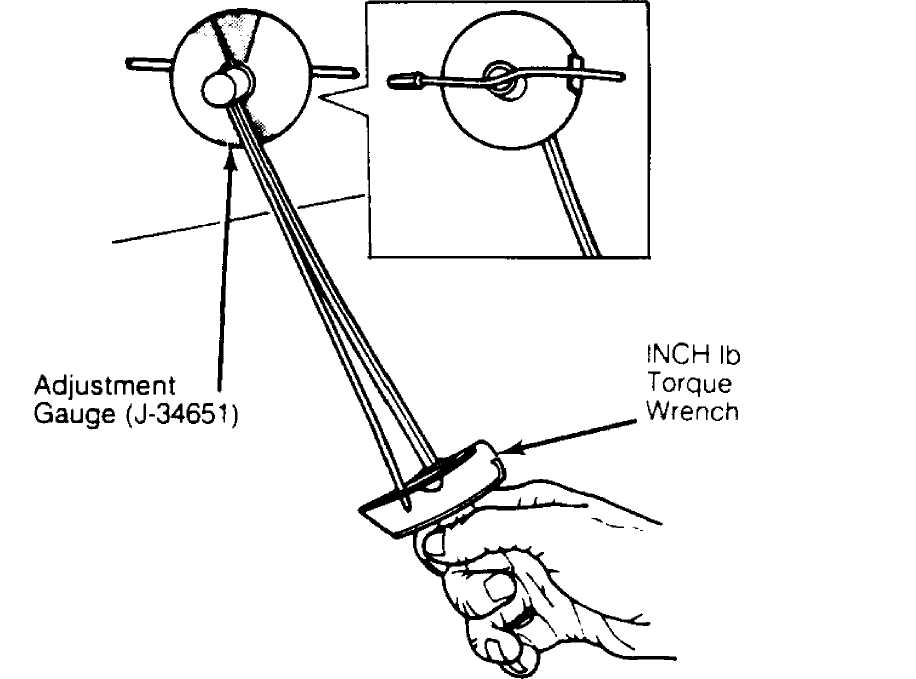
Place parking brake lever in fifth notch. Raise and
support vehicle. Position Adjustment Gauge (J-34651) on one of rear
parking brake cables. See Fig. 3. Apply and hold a torque of 50 INCH
lbs. (6 N.m) on adjustment gauge, and note position of gauge pointer.
If adjustment gauge pointer is not within okay band, turn
parking brake cable equalizer adjustment nut in or out until pointer
is within okay band. Remove tools, and lower vehicle. Ensure proper
parking brake operation.
30086
Fig. 3: Adjusting Parking Brake Courtesy of Chrysler Motors.
(Cherokee & Wrangler)
Grand Cherokee & Grand Wagoneer
1) Adjust rear brakes. See REAR BRAKE SHOES under ADJUSTMENTS
. Check cable for binding, kinking or fraying. Replace cable as required.
Fully apply parking brake. Raise and support vehicle. Mark
position of adjusting nut on threaded end of cable tensioner. Tighten
adjusting nut about 1/2" (13 mm). Replace tensioner if there are not
enough threads for proper adjustment.
Lower vehicle until wheels are about 6" off floor. Release
parking brake. Verify that rear wheels rotate freely and no drag is
felt. Lower vehicle, and ensure parking brake operates properly.
REAR BRAKE SHOES
NOTE: Brakes are self-adjusting. Under normal circumstances,
manual adjustment is only required if shoes are removed. Replace brake shoes when lining is 1/16" on bonded linings and 1/32" from rivet on riveted linings.
Raise and support vehicle. Remove wheels and brake drums.
Ensure right and left automatic adjuster lever and cable are properly
connected.
Insert Brake Shoe Adjustment Gauge (J-21177-01) in drum.
See Fig. 4. Expand gauge until inner legs contact drum braking
surface. Lock gauge in position.
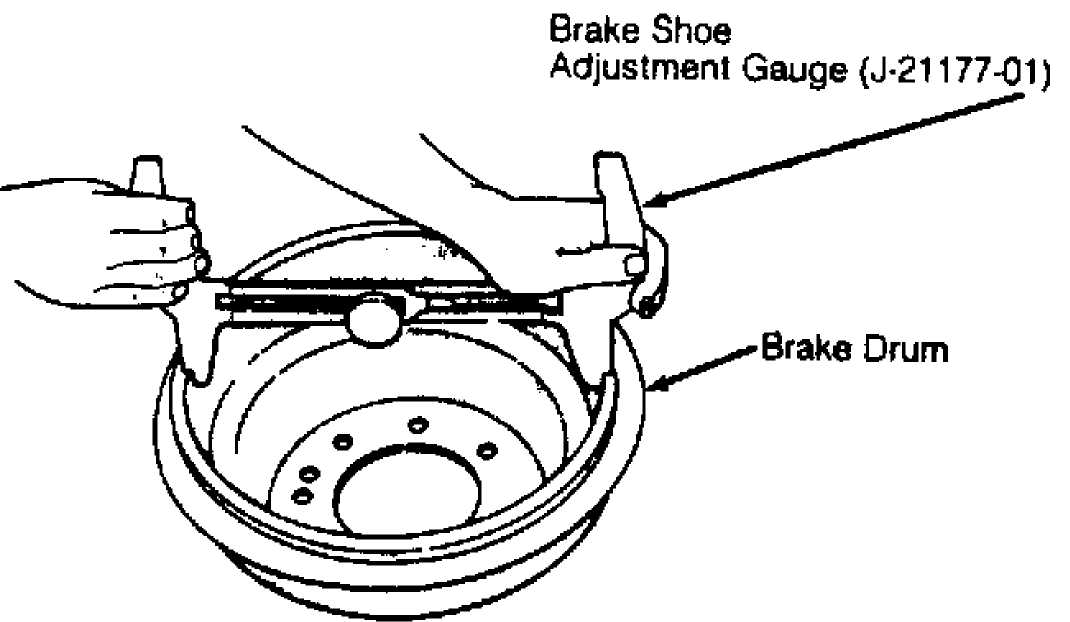
Fig. 4: Measuring Brake Drum Diameter Courtesy of Chrysler Motors.
Reverse brake shoe adjustment gauge, and install it on
brake shoes. See Fig. 5. Position gauge legs at shoe centers. If gauge
does not fit (too loose or too tight), adjust brake shoes accordingly.
Turn star adjuster wheel (by hand) to expand or retract
brake shoes. Continue adjustment until gauge outside legs have a
slight drag on shoes. Repeat procedure on opposite brake shoe
assembly.
5) Install brake drum and wheels. Lower vehicle. Make final adjustment by driving vehicle and making one forward stop (complete stop), followed by one reverse stop (complete stop). Repeat procedure 8-10 times to operate automatic adjusters and equalize adjustment.
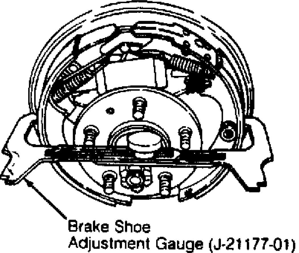
Fig. 5: Measuring Brake Shoe Diameter Courtesy of Chrysler Motors.
STOPLIGHT SWITCH
Move brake pedal forward by hand until free play is taken up. If clearance between stoplight switch plunger and brake pedal is 1/8" (3 mm) and stoplight functions properly, no adjustment is needed. If adjustment is necessary, press brake pedal forward by hand. Push stoplight switch forward in mounting bracket as far as possible. Grasp brake pedal and pull rearward to stop and release. Recheck clearance and stoplight operation.
TESTING
POWER BOOSTER
Master Cylinder/Power Booster
Start engine, and check power booster vacuum hose for
leaks. Repair as required. Stop engine, and place gear selector in
Neutral. Pump brake pedal until all vacuum reserve is depleted.
Press and hold brake pedal under light foot pressure. If
pedal does not hold firm and falls away, master cylinder is leaking
internally. Repair or replace as required. If brake pedal holds firm,
proceed to next step.
While holding light pressure on pedal, start engine, and
note pedal action. If no pedal action is noticeable, power booster or
vacuum check valve is faulty. Replace check valve, and repeat test. If
pedal falls away slightly then holds firm, proceed to next step.
Release brake pedal. Increase engine speed to 1500 RPM,
close throttle and immediately stop engine. Wait at least 90 seconds
and retest pedal action. Booster should provide 2 or more vacuum
assisted pedal applications. If pedal action is not as specified,
perform CHECK VALVE & POWER BOOSTER VACUUM test.
Check Valve & Power Booster Vacuum
Disconnect vacuum hose from check valve. Remove check
valve and seal from booster. Using a hand-held vacuum pump, apply 15-
20 in. Hg at large end of check valve. If gauge on pump indicates any
vacuum loss, valve is faulty and must be replaced. If gauge holds
steadily, proceed to next step.
Reinstall check valve and seal into power booster. Tee a
vacuum gauge into vacuum hose between power booster and vacuum source.
Start engine, and let idle one minute. Clamp hose shut between vacuum
source and power booster.
Stop engine, and observe vacuum gauge. If vacuum drops
more than one in. Hg within 15 seconds, booster diaphragm or check
valve is faulty. Replace as required.
BRAKE WARNING LIGHT SYSTEM
Electrical Circuit
Disconnect wire from switch terminal, and ground wire to chassis. Turn ignition on. Warning light should come on. If light does not operate, bulb or wiring circuit is defective. Replace bulb or repair wiring as necessary. If light illuminates, turn off ignition, and connect wire.
Warning Light Switch
Attach a bleeder hose to bleeder valve at either rear
brake. Immerse other end of hose in container with brake fluid. Turn
ignition on.
Open bleeder valve while pressure is being applied to
brake pedal. Warning light should activate. Close bleeder valve before
pressure is released from pedal.
Reapply brake pedal using moderate to heavy pressure.
Light should go out. Repeat test on front brake system. System should
function in same manner. Turn ignition off.
If light does not operate as specified for either system
but comes on when electrical circuit is tested, warning light switch
portion of valve is defective.
REMOVAL & INSTALLATION
FRONT BRAKE CALIPER & BRAKE PADS
NOTE: Replace brake pads when lining is 1/32" (.8 mm) from rivet heads.
Removal
Drain about half of brake fluid from master cylinder
reservoir. Raise and support vehicle. Remove front wheels.
Place "C" clamp on caliper. Solid end of clamp should
contact back of caliper. Screw end should contact metal part of
outboard pad. Tighten "C" clamp until piston is forced to bottom of
bore.
On 4WD models, do not allow "C" clamp screw to bear
directly on outboard shoe retainer spring. If necessary, use wood or
metal spacer between pad and "C" clamp screw.
On all models, remove caliper mounting pins. Lift caliper
off rotor and anchor plate. On 4WD models, brake pads will remain
attached to caliper. On 2WD models, brake pads will remain on caliper
support.
On 4WD models, remove outboard pad. Press one end of
outboard pad inward to disengage pad lug, and rotate shoe outward
until retainer spring clears caliper. Press opposite end of pad inward
to disengage opposite pad lug, and rotate pad up and out of caliper.
To remove inboard pad, grasp ends of pad, and tilt pad outward to
release springs from caliper piston. Remove pad from piston.
On 2WD models, hold lower anti-rattle clip against support
bracket and remove outboard brake pad from caliper support. Remove
inboard brake pad and both anti-rattle clips from caliper support.
On all models, disconnect brakeline at caliper, and cap
hole to prevent contamination while removing caliper from vehicle.
Installation
To install, reverse removal procedure. Apply a light coat
of multipurpose grease to caliper sliding surfaces. Lubricate caliper
mounting pins and bushings with silicone.
Torque caliper mounting pins to specification. See, at the
end of this article, TORQUE SPECIFICATIONS. Add brake fluid to
reservoir. Apply brakes until brake pedal is firm. Check brake fluid
level.
ROTOR
NOTE: DO NOT disconnect brake hose from caliper unless caliper is to be disassembled.
Removal (2WD)
Raise and support vehicle. Remove front wheels. Remove
caliper. See FRONT BRAKE CALIPER & BRAKE PADS under REMOVAL &
INSTALLATION. Suspend caliper from frame or suspension with wire.
Remove cap, cotter pin, nut retainer, adjusting nut and
front bearing from spindle. Remove rotor from spindle. Remove grease
seal and rear bearing from hub.
Installation (2WD)
Clean, inspect and repack wheel bearings. Replace grease
seal. Coat spindle, bearing races and rotor hub cavity with grease.
Clean rotor surface as required.
To install, reverse removal procedure. Tighten spindle nut
to specification while rotating rotor to seat bearings. See, at the
end of this article, TORQUE SPECIFICATIONS. Apply brakes until brake
pedal is firm. Check brake fluid level.
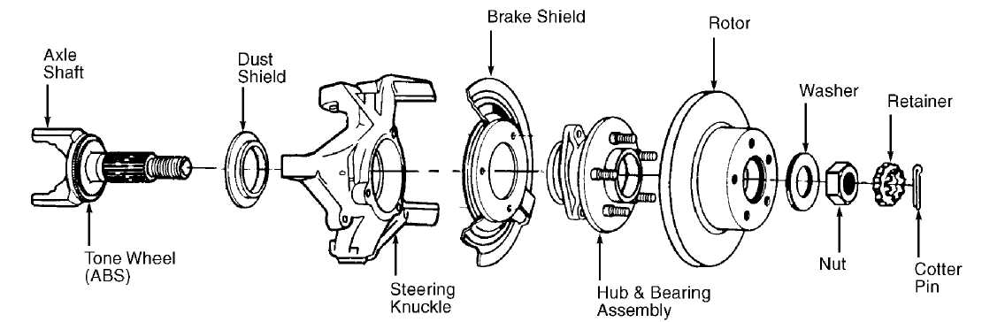
Removal & Installation (4WD)
Raise and support vehicle. Remove front wheels. Remove caliper. See, under REMOVAL & INSTALLATION, FRONT BRAKE CALIPER & BRAKE PADS. Suspend caliper from frame or suspension. Remove retainers securing rotor to hub. Remove rotor from hub. To install, reverse removal procedure. See Fig. 6.
92D21835
Fig. 6: Exploded View Of Rotor & Hub Assembly Courtesy of Chrysler Motors.
REAR BRAKE SHOES
Removal
Raise and support vehicle. Remove wheels and brake drum.
Remove "U" clip and washer from parking brake lever pivot pin. Place
Wheel Cylinder Clamp (J-8002) over wheel cylinder.
Remove primary and secondary shoe return springs, hold-
down spring and retainers and pins. See Fig. 7 or 8. Remove self-
adjuster lever, adjuster and adjuster spring from brake shoes.
Remove brake shoes. Disconnect parking brake cable from
parking brake lever, and remove lever.
Shoe Return Springs
Cable Guide
Adjuster Lever
Adjuster Cable
Hold-Down Spring & Retainers
Secondary Shoe
Wheel Cylinder-To-Backing
Plate Seal
Hold-Down Pins
9. Access Plug
10. Backing Plate
Cable Hole Plug
Parking Brake Strut & Spring
Self-Adjuster Assembly
Hold-Down Spring
& Retainers
Primary Shoe
Shoe Guide Plate
Pin
Shoe Spring
Parking Brake Lever
Fig. 7: Rear Drum Brake Assembly (Cherokee & Wrangler) Courtesy of Chrysler Motors.
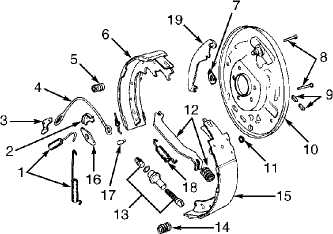
LEFT REAR BRAKE ASSEMBLY
 12
12
Primary Shoe
Hold-Down Pin
Anchor Pin
Backing Plate
Shoe Guide Plate
6. Parking Brake Lever
7 Secondary Shoe
8. Adjuster Cable
9. Cable Guide
Adjuster Lever
Shoe Spring
Spring Retainers
Hold-Down Spring
Adjuster Screw Assembly
Strut & Spring
Return Springs
Fig. 8: Rear Drum Brake Assembly (Grand Cherokee & Grand Wagoneer) Courtesy of Chrysler Motors.
Installation
Lubricate backing plate ledges, anchor pin, cable guide,
self-adjuster screw assembly, parking brake lever and lever pivot pin
with White lithium grease. See Fig. 7 or 8.
Connect parking brake lever to secondary brake shoe with
washer and "U" clip. Crimp ends of clip to secure clip on pivot.
Remove wheel cylinder clamp. Position brake shoes on brake support
plate, and install hold-down springs.
Install parking brake lever strut and spring. Install
cable guide plate and adjuster cable on anchor pin. Install primary
return spring. Install guide to secondary brake shoe. Install
secondary return spring.
Install adjuster screw, spring and lever. Connect lever to
cable. Using Brake Shoe Adjustment Gauge (J-21177-01), preset brake shoe adjustment. See REAR BRAKE SHOES under ADJUSTMENTS. Install brake drums. Install wheels, and lower vehicle. Check brake fluid. Road test vehicle.
OVERHAUL
NOTE: For overhaul, refer to appropriate illustration for exploded view of component. See Fig. 9 or 10.
CALIPER
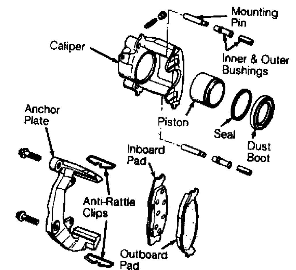
Fig. 9: Exploded View Of Caliper Assembly Courtesy of Chrysler Motors.
MASTER CYLINDER
NOTE:
On vehicles with Anti-Lock Brake System (ABS), manufacturer does not recommend overhaul of master cylinder. If defective, replace master cylinder and power brake booster as an assembly.
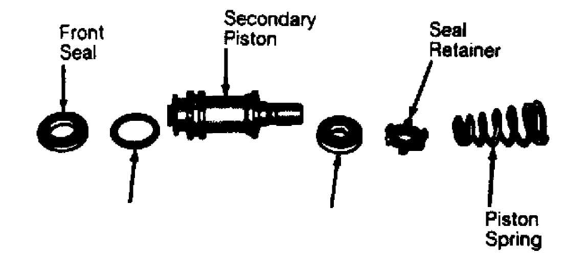 "0" RingRear
Seal
Fig. 10: Exp. View Of 2ndary Piston Components (Exc. Vehicles W/ ABS) Courtesy of Chrysler Motors.
TORQUE SPECIFICATIONS
TORQUE SPECIFICATIONS TABLE
Application Ft. Lbs. (N.m)
Backing Plate Bolt 32 (43)
Brake Hose-To-Caliper 23 (31)
Brakeline-To-Master Cylinder 15 (21)
Brakeline-To-Wheel Cylinder 13 (18)
Caliper Mounting Pins
2WD 25-35 (34-47)
4WD 7-15 (10-20)
Master Cylinder-To-Power Booster Nuts 15 (21)
Wheel Bearing (1) 17-25 (23-34)
Wheel Lug Nuts
Cherokee & Wrangler 75 (102)
Grand Cherokee & Grand Wagoneer 88 (120)
INCH Lbs. (N.m)
Wheel Cylinder Bolts 72-156 (8-18)
(1) - Tighten bearing nut while rotating wheel. Loosen nut 1/2 turn, and retighten to 19 INCH lbs. (2 N.m).
DISC BRAKE SPECIFICATIONS
DISC BRAKE ROTOR SPECIFICATIONS TABLE
Application In. (mm)
Disc Diameter 11.02 (279.9)
Lateral Runout
Cherokee & Wrangler 003 (.08)
Grand Cherokee & Grand Wagoneer 005 (. 13)
Parallelism 0005 (.013)
Original Thickness (1)
Minimum Refinish Thickness
Cherokee
2WD 86 (22)
4WD 89 (23)
All Others 89 (23)
(1) - Information is not available.
DRUM BRAKE SPECIFICATIONS
DRUM BRAKE SPECIFICATIONS TABLE
Application In. (mm)
Drum Diameter
Cherokee & Wrangler 9.00 (228.6)
Grand Cherokee & Grand Wagoneer (1)
Drum Width ( 1)
Maximum Drum Refinish Diameter
Cherokee & Wrangler 9.050 (230.00)
Grand Cherokee & Grand Wagoneer (1)
Wheel Cylinder Diameter (1)
Master Cylinder Diameter (1)
(1) - Information is not available.