Ā
1993 Jeep Cherokee
1993 ELECTRICAL
Chrysler Corp. Starters - Bosch & Mitsubishi
Jeep; Cherokee, Grand Cherokee, Wrangler
DESCRIPTION
Both Bosch and Mitsubishi starters are permanent-magnet type. A planetary gear train transmits power between starter motor and pinion shaft. Both starters are 12-volt units with solenoid mounted on starter housing.
TROUBLE SHOOTING
STARTER MOTOR NOISE
STARTER TROUBLE SHOOTING CHART
|
CONDITION |
POSSIBLE CAUSE |
CORRECTION |
|
Very high frequency whine before engine starts; engine starts ok |
Excessive distance between pinion gear and flywheel/drive plate gear. |
Shim starter motor toward flywheel/ drive plate. |
|
Very high frequency whine after engine starts with ignition key released, engine starts okay. |
Insufficient distance between starter motor pinion gear & flywheel/ drive plate runout can cause noise to be intermittent. |
Shim starter away from flywheel/drive plate. Check flywheel drive plate for bent, unusual wear, and excess runout. Replace flywheel/ drive plate as needed. |
|
A loud "whoop" after engine starts while starter motor is engaged. |
Most probably cause is defective overrun clutch. Overrun clutch replacement normally corrects this condition. |
Replace overrun clutch or drive assembly. |
|
A "Rumble, " "Growl," or "Knock" as starter motor coasts to stop after engine starts. |
Most probably cause is, bent or unbalanced starter motor armature. Armature replacement normally corrects this condition. |
Replace starter motor armature. |
TESTING (ON-VEHICLE)
COLD CRANKING TEST
NOTE: Ensure battery is fully charged. A cold engine increases starter draw amperage.
1) Connect battery load/charging system tester to battery,
and connect remote starter switch to starter relay. Set voltmeter selector to 18-volt position. Adjust ammeter reading to zero.
2) Disconnect coil wire from distributor cap. Attach coil wire to ground to prevent engine from starting. Crank engine, and note cranking voltage and amperage. Replace or repair starter if it is not to specifications. See appropriate STARTER SPECIFICATIONS.
STARTER RELAY TEST
Remove starter relay from Power Distribution Center (PDC).
Using an ohmmeter, check for continuity between terminals No. 30 and
87A. If no continuity exists, replace relay. See Fig. 1.
Check resistance between terminals No. 85 and 86. If
resistance is not 70-80 ohms, replace starter relay.
Connect battery to terminals No. 85 and 86. Check for
continuity between terminals No. 30 and 87. If no continuity exists,
replace starter relay.

93C76101
Fig. 1: Identifying Starter Relay Terminals Courtesy of Chrysler Corp.
SOLENOID TEST
Continuity Test
Disconnect wire from solenoid field coil terminal (large
terminal connected to starter body). Using an ohmmeter, test for
continuity between field terminal and solenoid terminal (small
terminal). Continuity should exist.
Test for continuity between solenoid terminal and solenoid
housing. Continuity should exist. If continuity does not exist in
either test, solenoid has open circuit. Replace solenoid.
Functional Test
With a fully-charged battery, connect a heavy gauge jumper
wire between battery terminal and solenoid terminal wire connector at
starter relay. If engine cranks, solenoid is okay.
If engine does not crank, check battery cable for voltage
to starter solenoid BAT terminal. Jump starter relay terminals as in
step 1), checking for voltage at solenoid terminal No. 50. Repair as
necessary. If engine still does not crank, repair or replace starter.
BENCH TESTING
ARMATURE TEST
Short Circuit
Place armature in a growler. While rotating armature slowly, hold growlerÆs blade parallel to and touching armature core. Blade vibrates if armature is shorted. Replace shorted armature.
Ground
Fig. 2: Testing Starter Armature For Ground Courtesy of Chrysler Corp.
DRIVE CLUTCH CHECK
Using growler or a self-powered test light, touch one lead to armature shaft and other lead to each commutator bar. See Fig. 2. If light glows at any point during procedure, armature is grounded. Replace grounded armature.

While holding drive clutch housing, rotate pinion. Drive pinion should rotate smoothly in only one direction (pinion should engage and lock in opposite direction). If drive unit does not operate properly or if pinion is worn or burred, replace drive clutch.
REMOVAL & INSTALLATION
STARTER
Removal & Installation (2.5L)
Disconnect negative battery cable. Remove exhaust pipe
clamp from bracket. See Fig. 3. On Cherokee with automatic
transmission, remove nut and bolt from forward end of brace rod.
Remove brace rod and bracket.
On vehicles with manual transmission, remove nut, bolt and
bracket from bellhousing. On all models, disconnect battery cable and
solenoid feed wire from starter solenoid. To install, reverse removal
procedure.
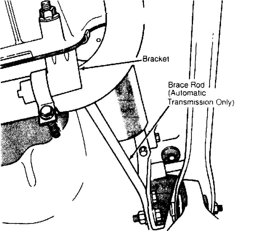
Fig. 3: Removing Engine Exhaust Clamp & Brace (2.5L) Courtesy of Chrysler Corp.
Removal & Installation (4.0L)
Disconnect negative battery cable. Raise and support vehicle.
Disconnect starter battery cable and solenoid feed wire. Remove starter from flywheel housing. To install, reverse removal procedure.
OVERHAUL
NOTE: For exploded views of starters, see Figs. 4 and 5.
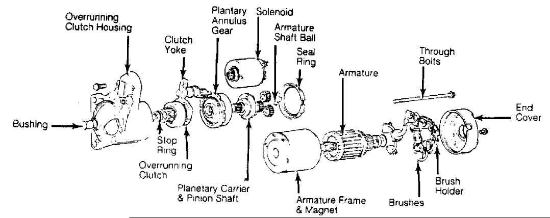
Fig. 4: Exploded View Of Mitsubishi Starter (4.0L) Courtesy of Chrysler Corp.
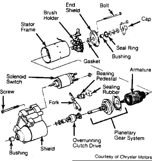
Fig. 5: Exploded View Of Bosch Starter (2.5L) Courtesy of Chrysler Corp.
STARTER SPECIFICATIONS
BOSCH
BOSCH STARTER SPECIFICATIONS TABLE
Application Specification
Carbon Brush Minimum Length 314" (8.0 mm)
Commutator
Diameter 1.23-1.27" (31.2-32.3 mm)
Runout 0004" (.01mm)
Armature
Core Runout 002" (.05 mm)
End Play 002" (.05 mm)
Cranking Test
Test Voltage 12.5 Volts
Minimum Voltage 9.6 Volts
Amps 160 Amps
No-Load Test @ 11.5 Volts
Maximum Amps 7 5 Amps
Minimum RPM 2900 RPM
Solenoid Hold-In Test Winding Voltage 2-2 Volts
Solenoid Pull-In Test Winding Voltage 6-7.3 Volts
MITSUBISHI
MITSUBISHI STARTER SPECIFICATIONS TABLE
Application Specification
Carbon Brush Minimum Length 354" (9 mm)
Commutator
Diameter 1.118-1.161" (28.4-29.5 mm)
Runout 001" (.03 mm)
Armature
Core Runout 003" (.08 mm)
End Play 023" ( .58 mm)
Cranking Test
Test Voltage 12.5 Volts
Minimum Voltage 9.6 Volts
Amps 130
No-Load Test @ 11.5 Volts
Maximum Amps 80 Amps
Minimum RPM 2500 RPM
Solenoid Hold-In Test Winding Voltage ... 3.5 Volts (Min.)
Solenoid Pull-In Test Winding Voltage ... 7.8 Volts (Max.)
TORQUE SPECIFICATIONS
TORQUE SPECIFICATIONS TABLE
Application Ft. Lbs. (N.m)
Starter-To-Block Bolts 33 (45)