A/C-HEATER SYSTEM - MANUAL
1993 Jeep Cherokee
1993 AIR CONDITIONING & HEAT
Chrysler Motors Manual A/C-Heater Systems
Jeep; Cherokee & Wrangler A/C SYSTEMS SPECIFICATIONS
SPECIFICATIONS TABLE
Application Specification
Compressor Type Sanden SD-709 7-Cyl.
Compressor Belt Tension
Serpentine Belt
New 180-200 lbs. (82-91 kg)
Used 140-160 lbs. (64-73 kg)
System Oil Capacity 4.6 ozs.
Refrigerant (R-12) Capacity
Cherokee 38.0 ozs.
Wrangler 32.0 ozs.
System Operating Pressures
High Side 160-235 psi (11.2-16.5 kg/cm)
Low Side 30-35 psi (2.1-2.5 kg/cm)
DESCRIPTION & OPERATION
A/C-HEATER SYSTEM
Cherokee
The A/C clutch relay controls voltage supply to the
compressor clutch. Electronic Control Unit (ECU) energizes the A/C clutch relay. ECU will not energize relay if evaporator temperature is too low, or if the refrigerant system pressure is too low.
ECU monitors evaporator temperature based upon the voltage reference it receives from the A/C sensor (evaporator thermistor) in the evaporator housing. ECU monitors refrigerant pressure through low pressure switch on receiver-drier. If refrigerant pressure is less than 28 psi (2.0 kg/cm), the low pressure switch contacts open. ECU then stops compressor operation to prevent damaging the compressor.
NOTE: ECU may delay compressor clutch engagement for as many as 30 seconds.
Wrangler
The A/C clutch relay controls voltage supply to the
compressor clutch. Electronic Control Unit (ECU) energizes the A/C clutch relay. ECU will not energize relay if evaporator temperature is too low, or if the refrigerant system pressure is too low.
If the switch contacts in the A/C thermostat are open
(indicating evaporator temperature is too low), or if the low pressure switch contacts are open (indicating refrigerant system pressure is too low), the ECU will not energize the A/C clutch relay. A/C thermostat (temperature control thermostat) is in evaporator housing. Low pressure switch is on receiver-drier. System uses a 3-speed blower motor instead of a blower resistor.
CONTROL PANEL
Cherokee
The mode control lever (upper lever) operates a vacuum switch on the back of the control panel. The vacuum switch controls vacuum to defroster, floor, panel and fresh/recirculated air vacuum motors, as well as a vacuum-actuated heater control valve (water valve). The heater control valve closes when vacuum is applied to it.
The A/C switch is closed when the lever is in any of the A/C modes (MAX, NORM or BI-LEVEL). The temperature control lever (lower lever) moves a cable that controls the position of the blend-air door in the heater case.
Wrangler
The mode control lever (upper lever) moves 2 cables, one for the vent doors and one for the defrost/floor duct door. Lever also operates a vacuum switch on back of control panel.
The vacuum switch allows or denies vacuum to the fresh air door vacuum motor. The temperature control lever (lower lever) moves a cable that controls the position of the blend-air door in the heater case.
NOTE: System does not use a heater control valve (water valve). Coolant always flows through the heater core.
TROUBLE SHOOTING
INSUFFICIENT OR NO COOL AIR
Check
blower motor operation. If blower motor operates, go
to next
step. If blower motor does not operate, check fuse. If fuse
is
blown, replace fuse. If fuse is
okay, apply battery voltage directly
to blower motor. If blower
motor does not operate, replace blower
motor. If blower motor
operates, replace blower switch or repair wire
harness.
Ensure
airflow is correct. If airflow is not correct,
check
for correct operation of air distribution doors and for
obstructions
in vent channels. If airflow is correct, ensure
compressor clutch
is operating and drive belt is tightened to
specification.
Go to step 4).
If
compressor clutch does not operate, check for battery
voltage at
compressor clutch connector. If voltage is present, replace
the
clutch. If voltage is not present, perform COMPRESSOR CLUTCH
CIRCUIT
test under TESTING.
Check
refrigerant system for proper charge. Evacuate and
charge system
if necessary. Check pressure switch and replace if
necessary.
Check A/C sensor (Cherokee) or A/C thermostat (Wrangler)
and
replace if necessary. Check expansion valve and replace
if
necessary.
TESTING
A/C CLUTCH RELAY
Cherokee
A/C clutch
relay is in engine compartment, in power
distribution center.
With engine at idle and MAX or NORM position
selected, check
voltage at Dark Blue/White wire of relay connector.
If voltage
is not present, check for open Dark Blue/White
wire or blown fuse
F6 in power distribution center. If voltage is
present, ground
the Dark Blue/Orange wire at relay. If clutch engages,
relay is
okay. If clutch does not engage, replace relay.
BLOWER MOTOR
Using an
ohmmeter, check resistance between blower motor
housing and
chassis ground. Zero ohms should be present. If resistance
is
zero, go to next step. If resistance is more than zero ohms,
repair
ground connection.
Disconnect
blower motor connector. Apply battery voltage
to blower motor
connector. Replace motor if it does not operate
smoothly at high
speed.
BLOWER MOTOR CIRCUIT
Wrangler
Turn
ignition on. Check voltage at ignition switch side of
fuse
No. 12. If no voltage is present, repair
open in Black/Orange
wire between fuse No. 12 and
ignition switch. If battery voltage is
present, check voltage on
other side of fuse.
If
battery voltage is not present, replace fuse. If
battery voltage
is present, check voltage at White wire terminal of
blower
switch. If battery voltage is present, go to next step. If
battery
voltage is not present, repair open White wire circuit between
fuse
No. 12 and blower switch.
With
blower switch in LO position, check voltage at Dark
Blue wire
terminal of blower switch connector. If battery voltage is
not
present, replace blower switch. If battery voltage is present, go
to
next step.
With
blower switch in MED position, check voltage at Green
wire
terminal. If battery voltage is not present, replace blower
switch.
If battery voltage is present, go to next step.
With
blower switch in HI position, check voltage at Orange
wire
terminal. If battery voltage is not present, replace blower
switch.
If battery voltage is present, go to next step.
Turn
ignition off. Check resistance between blower motor
housing and
chassis ground. If resistance is not zero ohms, repair
ground
wire between blower motor and ground. If resistance is zero
ohms,
go to next step.
Turn
ignition on. With blower switch in LO position, check
voltage at
Dark Blue wire terminal of blower motor connector. If
battery
voltage is present, go to next step. If battery voltage is
not
present, repair Dark Blue wire between blower switch and
blower motor.
With
blower switch in MED position, check voltage at Green
wire
terminal. If battery voltage is present, go to next step. If
battery
voltage is not present, repair Green wire between blower
switch
and blower motor.
With
blower switch in HI position, check voltage at Orange
wire
terminal. If battery voltage is present, blower motor circuit
is
okay. If battery voltage is not present, repair Orange wire
between
blower switch and blower motor.
NOTE: If blower motor fails to operate, and battery voltage was present at Dark Blue, Green and Orange wires, replace blower motor.
COMPRESSOR CLUTCH CIRCUIT
Cherokee
Apply
battery voltage to compressor clutch connector
terminal. If
clutch engages, go to next step. If clutch does not
engage,
connect a jumper wire between clutch coil frame and chassis
ground.
If clutch engages, repair clutch coil ground circuit. If
clutch
does not engage, replace clutch coil.
Turn ignition and blower switch on. Set control lever to
MAX or NORM position. Check voltage at Light Green wire terminal of low pressure switch connector. If battery voltage is not present, repair circuit between low pressure switch and control panel.
If battery
voltage is present, check voltage at Dark
Blue/Orange wire
terminal of low pressure switch connector. If battery
voltage is
present, go to next step. If battery voltage is not
present,
check refrigerant system charge. Recharge system if
undercharged.
If refrigerant system charge is okay, replace low
pressure
switch.
Start
engine. Check voltage at Dark Blue/Black wire
terminal
of A/C clutch relay connector. If battery voltage is not
present,
check fuse No. 6 in engine compartment
fuse block. Replace
fuse if blown. If battery voltage is present,
connect a jumper wire
between ground
and Dark Blue/Orange wire terminal of A/C clutch relay
connector.
If clutch does not engage, check wiring to ECU.
Wrangler
Apply
battery voltage to compressor clutch connector
terminal. If
clutch engages, go to next step. If clutch does not
engage,
connect a jumper wire between clutch coil frame and chassis
ground.
If clutch engages, repair clutch coil ground circuit. If
clutch
does not engage, replace clutch coil.
Turn
ignition and blower switch on. Set control lever to
MAX position.
Check voltage at Light Blue/Black wire terminal of low
pressure
switch connector. If battery voltage is not present, go to
step
4). If battery voltage is present, check
continuity between low
pressure switch
terminals.
If there
is continuity, repair open Light Blue/Red wire
circuit between
low pressure switch and ECU. If there is no
continuity, check
refrigerant system charge. Recharge system if
undercharged. If
system charge is okay, replace low pressure switch.
NOTE: Both wire terminals at the A/C thermostat connector are
Light Blue. It will be necessary to determine which wire is the circuit from the blower switch.
Check
voltage at Light Blue wire terminal of A/C
thermostat connector
(wire that leads to A/C blower switch). See
WIRING
DIAGRAMS. If battery voltage is not present, repair open Light
Blue
wire circuit between A/C thermostat and blower switch.
If
battery voltage is present, check voltage at other
Light
Blue wire of A/C thermostat. If battery voltage is not
present,
replace A/C thermostat. If
battery voltage is present, repair open
Light Blue/Black wire
circuit between low pressure switch and A/C
thermostat.
REMOVAL & INSTALLATION
A/C SENSOR
Removal & Installation (Cherokee)
Disconnect negative battery cable. Remove center console (if equipped). Remove lower instrument panel. Disconnect A/C sensor connector. See Fig. 1. Carefully remove A/C sensor and capillary tube from hole in housing. Avoid bending capillary tube. To install, reverse removal procedure.
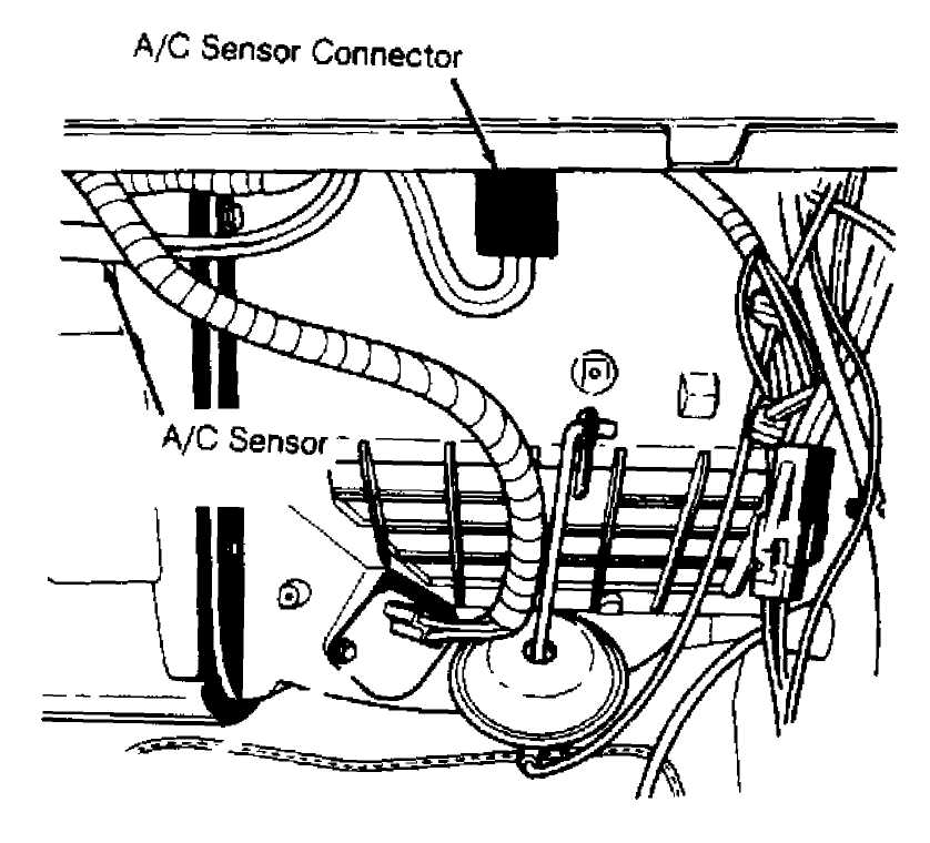
Fig. 1: Locating A/C Sensor (Cherokee) Courtesy of Chrysler Corp.
A/C THERMOSTAT
Removal (Wrangler)
═╧╥7╬╥.╥„ Remove evaporator housing. See EVAPORATOR & EVAPORATOR HOUSING under REMOVAL & INSTALLATION. Remove screws holding top and A/C ?hermostSt S°usi??: Separate housing halves. Carefully remove A/C thermostat and capillary tube. Avoid bending capillary tube.
Installation
Insert capillary tube into evaporator core at least 2" (51 mm), and about 2.5" (64 mm) from top of evaporator. See Fig. 2 116™0^^ T° complete installation, reverse removal F
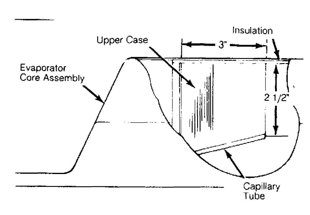
Fig. 2: Positioning Capillary Tube In Evaporator (Wrangler) (Cross-Sectional View Shown) Courtesy of Chrysler Corp.
COMPRESSOR
NOTE: System charge can be retained by isolating compressor from rest of system. This eliminates the need to evacuate and recharge system after installation. To isolate compressor, begin removal procedure at step 1). If fully discharging system, begin at step 3).
Removal
Connect
service gauges. Close both valves on gauge. Set
both service
valves to mid-position. Start engine. Turn on A/C. Slowly
turn
low-side service valve clockwise toward front-seated position.
When
low-side pressure is zero, stop the engine, turn off
the A/C and
quickly front-seat the low-side service valve. Front-seat
the
high-side service valve. Loosen the oil level check plug on
the
compressor to release any pressure in the compressor.
Disconnect
negative battery cable. Disconnect clutch
connector.
Discharge A/C system using approved refrigerant
recovery/recycling
equipment (if compressor was not isolated).
With hoses
attached to service valves, remove service
valves from
compressor. Remove drive belt. Remove compressor bolts
and
compressor.
Installation
To
install, reverse removal procedure. If system was fully
discharged,
evacuate and charge system. If compressor was isolated
before
removal, air must be purged from compressor after service valve
and
hose assemblies are reconnected to compressor.
To purge
air, cap the service gauge ports on both service
valves. Turn
low-side service valve counterclockwise until it stops
(back-seated). This allows refrigerant to enter compressor. Set high-side service valve to mid-position.
3) Loosen
gauge port cap on high-side service valve to allow
refrigerant to
purge air from the compressor. Back-seat high-side
service
valve, and then tighten gauge port cap. Air is now purged
from
compressor.
CONDENSER
Removal (Cherokee - 2.5L)
Drain
coolant from radiator. Disconnect fan shroud and
radiator hoses.
Disconnect automatic transmission cooler lines (if
equipped).
Discharge A/C system using approved
refrigerant
recovery/recycling
equipment.
Disconnect
refrigerant hoses from condenser. Disconnect
low pressure switch
connector from switch on receiver-drier. Remove
radiator,
condenser and receiver-drier as an assembly. Separate
condenser
from radiator. Remove receiver-drier from condenser.
Installation
To install, reverse removal procedure. Add one ounce of refrigerant oil to system if replacing condenser. Fill cooling system. Evacuate and charge system.
Removal & Installation (Cherokee - 4.0L)
Remove
cooling fan shroud and cooling fan. Remove upper
crossmember and
bracket. Discharge A/C system using approved
refrigerant
recovery/recycling equipment. Disconnect A/C hoses from
condenser
and plug openings. Disconnect and separate condenser from
radiator.
Remove condenser.
To
install, reverse removal procedure. Add one ounce of
refrigerant
oil to system if replacing condenser. Fill cooling system.
Evacuate
and charge system.
Removal & Installation (Wrangler)
1) Discharge A/C system using approved refrigerant
recovery/recycling equipment. Drain cooling system. Remove cooling fan shroud and radiator. Disconnect liquid line from condenser. Remove condenser screws. Tilt bottom of condenser toward engine.
2) From
under vehicle, disconnect evaporator to receiver-
drier
hose from receiver-drier. Remove receiver-drier and condenser as
an
assembly. Remove receiver-drier from condenser. To install,
reverse
removal procedure. Fill cooling
system. Evacuate and charge system.
CONTROL PANEL
Removal & Installation
Disconnect
negative battery cable. Remove screws from
instrument panel
bezel. Remove bezel. Remove radio (if equipped).
Remove
control panel screws. Pull out control panel and
disconnect
vacuum hoses, wires and cables. Note locations for
installation
reference. Remove control panel. To install, reverse
removal
procedure.
RECEIVER-DRIER
Removal & Installation (Cherokee)
On 2.5L, remove condenser and receiver-drier as an assembly. See CONDENSER under REMOVAL & INSTALLATION. On 4.0L, discharge A/C system using approved refrigerant recovery/recycling equipment. Disconnect low pressure switch connector. Remove receiver-drier. To install, reverse removal procedure. Evacuate and charge system.
Removal & Installation (Wrangler) Discharge A/C system using approved refrigerant
recovery/recycling equipment. Disconnect refrigerant lines from receiver-drier. Remove receiver-drier. To install, reverse removal procedure. Evacuate and charge system.
EVAPORATOR & EVAPORATOR HOUSING
Removal & Installation (Cherokee)
Disconnect
negative battery cable. Discharge A/C system
using approved
refrigerant recovery/recycling equipment. Disconnect
blower motor
connector and vent tube.
Remove
console (if equipped). Remove lower
instrument
panel. Disconnect electrical connectors from blower
motor resistor and
A/C sensor. Disconnect vacuum hose at vacuum
motor. Cut plastic strap
holding evaporator housing to heater
core housing.
Disconnect
blend-air door control cable. Detach clip at
rear of blower
housing flange, and remove housing screws. Remove
housing nuts
from studs on engine compartment side of firewall. Remove
evaporator
drain tube.
Remove
right kick panel. Remove instrument panel support
bolt. Gently
pull on right side of instrument panel, then rotate
housing
downward and toward rear of vehicle to disengage housing studs
from
firewall.
Remove
evaporator housing. Disassemble evaporator housing
and remove
evaporator. To install, reverse removal procedure. Evacuate
and
charge system.
Removal & Installation (Wrangler)
1) Discharge A/C system using approved refrigerant
recovery/recycling equipment. Disconnect low-side refrigerant hose from compressor. Disconnect high-side refrigerant hose from receiver-drier.
2) Remove
evaporator housing-to-instrument panel screws and
bracket. Lower
evaporator housing, and pull hoses and grommet through
opening.
See Fig. 3. Disassemble evaporator housing
and remove
evaporator. To install,
reverse removal procedure. Evacuate and charge
system.

Fig. 3: Exploded View Of Evaporator Housing (Wrangler) Courtesy of Chrysler Corp.
EXPANSION VALVE
Removal & Installation (Cherokee) Discharge A/C system using approved refrigerant
recovery/recycling equipment. Remove coolant reservoir and bracket. Disconnect refrigerant hoses from expansion valve. Disconnect expansion valve from evaporator tubes. Remove expansion valve. To install, reverse removal procedure. Evacuate and charge system.
Removal & Installation (Wrangler) Discharge A/C system using approved refrigerant
recovery/recycling equipment. Remove evaporator housing. Remove insulation from expansion valve. See Fig. 3. Mark location of capillary tube on evaporator tubing. Disconnect refrigerant hose from expansion valve. Remove expansion valve. To install, reverse removal procedure. Evacuate and charge system.
TORQUE SPECIFICATIONS
TORQUE SPECIFICATIONS TABLE
Application Ft. Lbs. (N.m)
A/C Compressor Bolt 20 (27)
Refrigerant Hoses
Evaporator To Receiver-Drier 10 (14)
Expansion Valve To Evaporator 18 (24)
"O" Ring Fitting Type 24 (33)
Service Valve (Compressor Fitting) (1) 25 (34)
Steering Column Nut 20 (27)
(1) - Lubricate threads and "O" ring with compressor oil.
WIRING DIAGRAMS
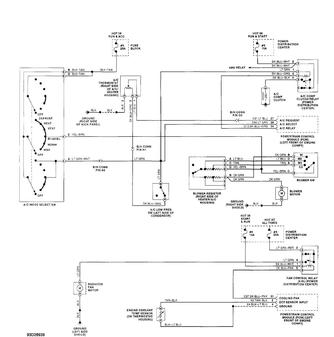
Fig. 4: Manual A/C-Heater System Wiring Diagram (Cherokee)
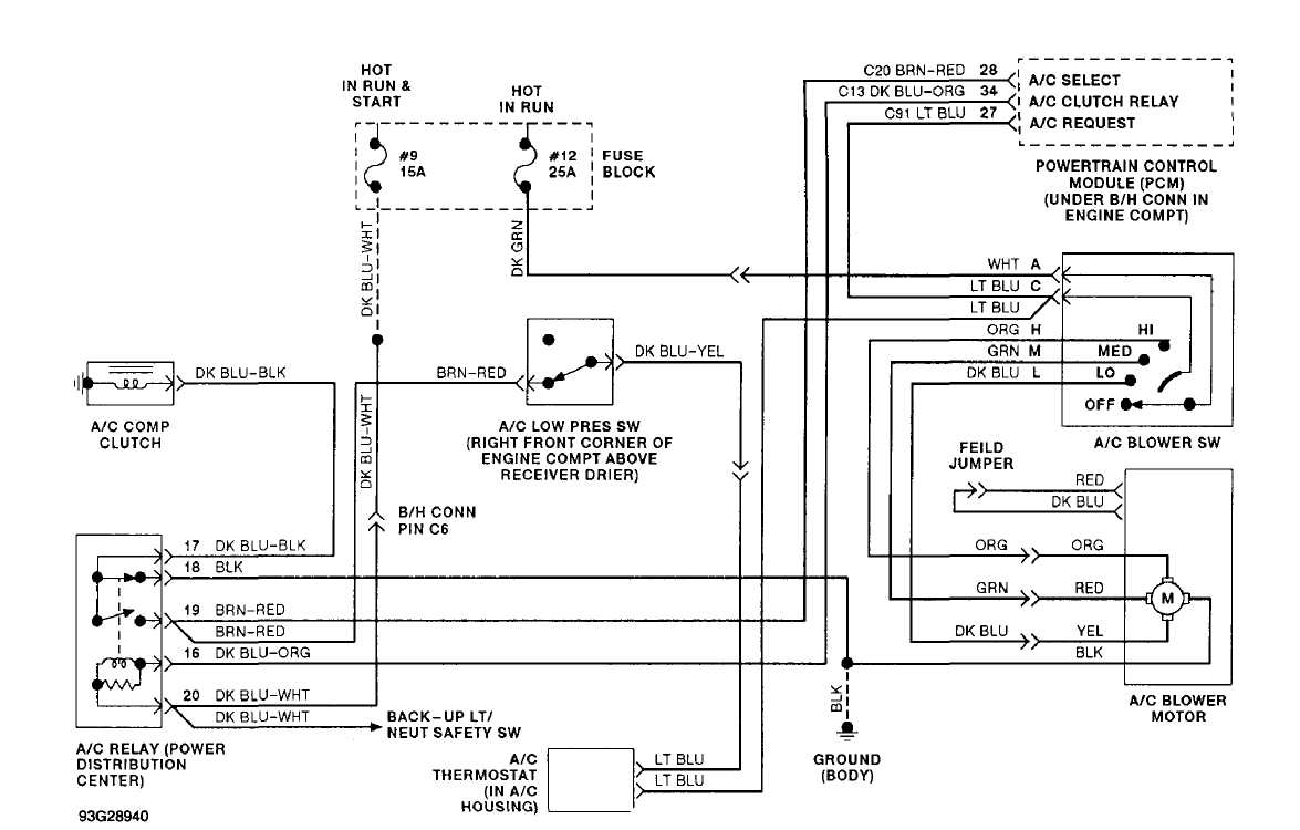
Fig. 5: Manual A/C-Heater System Wiring Diagram (Wrangler)