1993 Jeep Cherokee
1993 ACCESSORIES & EQUIPMENT Chrysler Corp. Wiper/Washer Systems
Jeep; Cherokee, Grand Cherokee, Grand Wagoneer, Wrangler
DESCRIPTION & OPERATION
All models use a standard wiper system with a 2-speed motor and electric washers. An optional system provides an intermittent cycle. Optional rear wiper/washer system is available.
ADJUSTMENTS
WIPER ARM ADJUSTMENT
Cherokee, Grand Cherokee & Grand Wagoneer
Ensure wiper shafts are in park position. Install driver-side wiper arm onto pivot shafts so that end of wiper arm is .9-2" (23-52 mm) above lower windshield reveal molding. Install passenger-side wiper arm so that its end is 1.3-2.4" (33-62 mm) above reveal molding. Blades should be parallel to lower reveal molding after installation. Install rear wiper arm (if equipped) so that midpoint of blade is .6-1.4" (15-35 mm) above lower window seal.
Wrangler
Ensure wiper shafts are in park position. Install both wiper arms onto pivot shafts so that end of wiper arms are 4 1/4-5 1/8" (108-130 mm) above lower windshield reveal molding. Blades should be parallel to each other after installation.
TESTING
FRONT WIPER MOTOR TEST
Cherokee, Grand Cherokee & Grand Wagoneer
Measure resistance between motor connector terminal No. 4
(Black wire) and ground. Resistance should be zero ohms. If resistance
is not as specified, repair open in Black wire.
Turn ignition switch to ACCY position. Set wiper switch in
any position. Using a voltmeter, measure voltage at motor connector
terminal No. 1 (Light Green/Black wire). If battery voltage exists but
motor is inoperative, replace motor. If battery voltage does not exit,
repair open in Light Green/Black wire. Recheck motor operation.
Set wiper switch in LO position. Check voltage at motor
connector terminal No. 2 (Tan/Red wire). If battery voltage exists but
motor is inoperative, replace motor. If battery voltage does not exit,
repair open in Tan/Red wire. Recheck motor operation.
Set wiper switch in HI position. Check voltage at motor
connector terminal No. 2 (Tan/Red wire). If battery voltage exists but
motor is inoperative, replace motor. If battery voltage does not
exist, repair open in Tan/Red wire. Recheck motor operation.
NOTE: On Cherokee, Brown/White wire at motor connector terminal No. 5 will change to Brown/Tan wire at splice between harness connector and motor connector.
5) Check voltage at motor connector terminal No. 5
(Brown/White wire). Turn wiper switch to OFF position while observing
voltmeter. Battery voltage should exist until wipers park. Voltage should then drop to zero volts. If voltage is as specified, but motor is inoperative, replace motor. If battery voltage is not as specified, repair open in Brown/White wire. Recheck motor operation.
Wrangler
Unplug wiper motor connector. Check for continuity between
harness connector terminal "E" (Black wire) and ground. If no
continuity exists, repair open circuit in Black wire to ground.
Reconnect wiring to motor.
Turn ignition switch to accessory position. With wiper
switch in any position, check for battery voltage at harness connector
terminal "B" (Dark Blue wire). If battery voltage is not present,
repair open circuit in Dark Blue wire from circuit breaker.
Set wiper switch to LO. Check for battery voltage at
harness connector terminal "A" (Brown/White wire). If battery voltage
is present, replace wiper motor. If battery voltage is not present,
repair open circuit in Brown/White wire to wiper switch.
Set wiper switch to HI. Check for battery voltage at
harness connector terminal "H" (Red/Yellow wire). If battery voltage
is present, replace wiper motor. If battery voltage is not present,
repair open circuit in Red/Yellow wire to wiper switch.
Check for battery voltage at harness connector terminal
"D" (Dark Green/Yellow wire). Set wiper switch to OFF. Battery voltage
should be present until wipers park, then drop to zero volts. If
voltage is as specified, replace motor. If voltage is not as
specified, repair open circuit in Dark Green/Yellow wire to wiper
switch.
FRONT WIPER SWITCH TEST
NOTE: All terminals specified in this test are on wiper switch connector for vehicles with standard wipers. For vehicles with intermittent wipers, specified terminals are on switch side connector of intermittent module. Module is on lower instrument panel cover, near steering column.
Cherokee & Wrangler
Turn ignition on. Check for battery voltage on terminal
"D" (White wire). If no voltage exists, repair open circuit in White
wire from circuit breaker.
Set wiper switch to LO. Measure voltage at terminal "E"
(Gray wire). If meter does not indicate battery voltage, replace
switch.
Set wiper switch to HI. Measure voltage at terminal "C"
(Purple wire). If meter does not indicate battery voltage, replace
switch.
Measure voltage at terminal "F" (Yellow wire). Meter
should indicate battery voltage. Set wiper switch to OFF. Meter should
indicate battery voltage until wipers park, then drop to zero volts.
If voltage is not as specified, replace switch.
For models with intermittent wipers, disconnect switch
side connector from module. With an ohmmeter, measure resistance
between terminals "A" (Dark Green wire) and "D" (White wire) while
rotating switch from minimum to maximum delay. If resistance does not
vary smoothly between 0-500,000 ohms, replace switch.
For models with intermittent wipers, disconnect switch
side connector from module. With an ohmmeter, measure resistance
between terminals "A" (Dark Green wire) and "G" (Brown wire) while
rotating switch from minimum to maximum delay. If resistance does not
vary smoothly between 0-500,000 ohms, replace switch.
Grand Cherokee & Grand Wagoneer
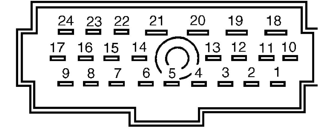
Disconnect multifunction switch harness connector. See FRONT WIPER SWITCH under REMOVAL & INSTALLATION. Using ohmmeter, check for continuity in wiper/washer terminals of multifunction switch with turned to listed wiper/washer positions. See Fig. 1. See WIPER SWITCH CONTINUITY (Grand Cherokee) table. If continuity is not as specified, multifunction switch must be replaced as an assembly.
93B76324
Fig. 1: Multifunction Switch Pin ID (Grand Cherokee & Grand Wagoneer) Courtesy of Chrysler Corp.
WIPER SWITCH CONTINUITY TABLE (GRAND CHEROKEE & GRAND WAGONEER)
Switch Position
Continuity Between Pins
Off 6 & 7
Delay (1) (2) 1&2, 1&4, 2&4, 4&9
Low 4 & 6
High 4 & 5
Wash 3 & 4
(1) - Resistance at maximum delay position should be
270,000-330,000 ohms.
(2) - Resistance at minimum delay position is zero ohms
with ohmmeter set on high ohm scale.
INTERMITTENT WIPER MODULE TEST
NOTE: DO NOT move switch to intermittent mode during following test. Damage to switch rheostat will result.
Test operation of all wiper functions. If any malfunction
is found, remove intermittent wiper module. Connect harness connectors
together. This will remove intermittent feature from system, for test
purposes. Turn ignition switch to ACCY position.
Move wiper switch through all positions EXCEPT
intermittent. If wiper system functions normally, replace intermittent wiper module. Retest wiper system. If wiper system does not function properly, see FRONT WIPER MOTOR TEST and/or FRONT WIPER SWITCH TEST.
FRONT WASHER MOTOR TEST
Unplug washer pump connector, under washer reservoir in
engine compartment. Check for continuity between harness connector
terminal "B" (Black wire) and ground. See Fig. 2. If no continuity
exists, repair open circuit in Black wire to ground.
Connect a jumper wire between terminal "B" on washer pump
and a known good ground. Using jumper wire with 15-amp in-line fuse,
supply battery voltage to washer pump terminal "A" (Brown wire on
Cherokee and Wrangler; Brown/Tan wire on Grand Cherokee and Grand
Wagoneer). Replace pump if it does not operate.
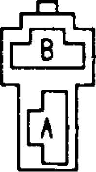
Fig. 2: Identifying Windshield Washer Pump Terminals (Typical) Courtesy of Chrysler Corp.
REAR WIPER MOTOR TEST
On Cherokee, Grand Cherokee and Grand Wagoneer, disconnect wiper/washer harness at tailgate connector. On Wrangler, disconnect harness connector to lift-off top. Connect jumper wire from Black wire to good ground on motor harness connector. Using jumper wire with in┬Łline 15-amp fuse, apply battery voltage to power feed terminal (Black/White wire on Cherokee; Brown/Light Green wire on Grand Cherokee, Grand Wagoneer and Wrangler). Wiper motor should operate.
Replace motor if inoperative. REAR WIPER SWITCH TEST
Cherokee
Turn ignition on. Check for battery voltage at terminal
"B" (Light Blue/Red wire) at rear wiper switch harness connector. If
no voltage exists, repair open circuit in Light Blue/Red wire to fuse
panel.
With rear wiper switch in any position, check for battery
voltage at terminal "D" (White wire). If no voltage is indicated at
terminal "D" (White wire), replace switch.
With switch in WASH position, check for battery voltage at
terminal "C" (Brown/Red wire). Repeat test with switch in WIPE
position. If no voltage is indicated in each position, replace switch.
With switch in WASH position, check for battery voltage at
terminal "A" (Black/White wire). If no voltage is indicated, replace
switch.
Grand Cherokee & Grand Wagoneer
1) Disconnect rear wiper switch and reconnect below dash
where terminals can be tested with voltmeter. See REAR WIPER SWITCH
under REMOVAL & INSTALLATION. Turn ignition switch to ON position.
Check for battery voltage at switch connector terminal No. 1
(Brown/Pink wire). If no voltage exists, check 30-amp fuse No. 9 in fuse box. Replace fuse, if necessary.
With switch in WASH position, check for battery voltage at
switch connector terminal No. 4 (Black/White wire). Replace switch if
battery voltage is not present.
With switch in ON position, check for battery voltage at
switch connector terminal No. 3 (Brown/Light Green wire). Replace
switch if battery voltage is not present.
With switch in DELAY position, check for battery voltage
at switch connector terminal No. 2 (Brown/Orange wire). Replace switch
if battery voltage is not present.
Wrangler
Unplug harness connector at rear wiper switch. Check for
continuity between terminal "C" (Black wire) at harness connector and
ground. If no continuity exists, repair open circuit in Black wire to
ground.
Turn wiper switch off. Check for continuity between
terminal "B" (Brown/Light Green wire) and terminal "C" (Black wire) at switch connector. If no continuity exists, replace switch. Reconnect wiring to switch.
Turn ignition on. Check for battery voltage at terminal
"P" (Brown/Yellow wire) at harness connector. If no voltage exists,
replace fuse or repair open circuit in Brown/Yellow wire to fuse
panel.
With switch in WASH position, check for battery voltage at
terminal "B" (Brown/Light Green wire) at harness connector. Repeat
test with switch in WIPER position. If no voltage exists, replace
switch.
With switch in WASH position, check for battery voltage at
terminal "A" (Brown/White wire) at harness connector. If no voltage
exists, replace switch.
REAR WASHER MOTOR TEST
1) Unplug washer pump connector, under washer reservoir in engine compartment. Check for continuity between harness connector terminal "A" (Black wire) and ground. If no continuity exists, repair open circuit in Black wire to ground.
2) Connect a jumper wire between terminal "A" on washer pump and a good ground. Supply battery voltage to washer pump terminal "B", using a jumper wire with a 15-amp in-line fuse. See Fig. 2. Pump should operate. If pump is inoperative, replace pump.
REMOVAL & INSTALLATION
FRONT WIPER MOTOR
Removal & Installation (Except Wrangler)
Remove wiper arms. Remove cowl trim. Disconnect washer hose. Remove cowl mounting bracket nuts and pivot pin screws. Disconnect wiring. Remove wiper motor. To install, reverse removal procedure. Adjust wiper blades. See WIPER ARM ADJUSTMENT under ADJUSTMENTS.
Removal & Installation (Wrangler)
Remove top, if installed. Remove windshield hold-down
bolts from lower corners of instrument panel. Remove wiper motor
mounting screws. Disconnect wiper linkage drive arm. Remove wiper
motor wire harness retaining clip. Pull motor and drive arm out
through access hole.
Pry drive arm from motor pivot. DO NOT remove pivot
attaching nut. Remove intermittent module bracket screws. Reach behind instrument panel to disconnect wiper motor harness. Remove wiper motor. To install, reverse removal procedure. Adjust wiper blades. See WIPER ARM ADJUSTMENT under ADJUSTMENTS.
FRONT WIPER SWITCH
Removal (Cherokee & Wrangler)
Disconnect negative battery cable. For vehicles with
optional steering wheel, push and turn horn button to remove it.
Remove retaining screws, bushing, receiver, flexplate and insulator.
On all models, remove 3 retaining screws and steering wheel cover.
Disconnect horn wiring. Remove grounding pin by pulling it
out gently. Remove steering wheel retaining nut and vibration damper.
Mark steering shaft and steering wheel for reassembly reference. Using
steering wheel puller, remove steering wheel.
CAUTION: Lock plate is retained by a high pressure spring. DO NOT remove snap ring without using a compressor tool.
Remove lock plate cover. Compress lock plate with Lock
Plate Compressor (C-4156). Remove lock plate retaining ring, lock
plate, canceling cam and spring. On vehicles with optional steering
wheel, remove horn button components from canceling cam. Discard lock
plate retaining ring.
Remove hazard warning switch knob, dimmer switch actuating
arm screw and turn signal switch attaching screws. On Cherokee, remove
lower instrument panel trim panel. On Wrangler, remove steering column
shroud screws. Slide shroud toward steering wheel. On all models,
apply pressure upward to shroud and downward to instrument panel to
free holding tabs.
Remove cover under steering column. Remove PRNDL clip (if
equipped). Remove 2 nuts and 4 bolts from steering column bracket.
Loosen steering column brace nut at kick panel. Ease steering column
downward.
Unplug wiper switch connector. Tape wires to wiper
connector to ease harness removal. Remove wiring harness cover from
column. Pull turn signal switch out from column far enough for access
to retaining screws.
Turn ignition switch on. Insert paper clip below key
warning buzzer retainer to flatten retainer. Remove key warning buzzer and retaining clip as an assembly. DO NOT try to remove warning buzzer and retaining clip separately; clip could fall into column jacket. 8) Remove ignition lock cylinder retaining screw and lock cylinder. Remove attaching screws, housing and shroud. Ensure dimmer switch rod, lock pin and lock rack do not fall out. Remove turn signal/wiper switch lever from housing. Remove wiper switch cover from rear of housing. Remove pivot screw and wiper switch.
Installation (Cherokee & Wrangler)
Install NEW switch. Push dimmer switch rod to ensure it is
connected. Position housing to column. Ensure nylon spring retainer is
forward of lock rack retaining slot. Position first tooth of gear so
that it engages with first tooth of lock rack.
Install housing attaching screws and key lock cylinder.
Carefully tighten screws while mating housing to column. Turn key to
ensure lock pin extends fully when ignition switch is locked.
To complete installation, reverse removal procedure.
Install NEW lock plate retaining ring. Ensure wires are flat against
inside column. Ensure PRNDL cable clip is installed so that pointer
aligns properly. Reinstall steering wheel and tighten nut to 25 ft.
lbs. (34 N.m).
Removal & Installation (Grand Cherokee & Grand Wagoneer)
Disconnect negative battery cable. Remove tilt lever (if
equipped). Remove upper and lower steering column trim covers. Remover
knee blocker. Remove steering column mounting nuts.
Lower steering column to gain access to rear of
multifunction switch. Using Remover (TTXR20B2), remove tamper-proof mounting screws. Gently pull multifunction switch away from steering column. Loosen connector screw sufficiently to remove connector. Screw will remain in connector. Remove connector. To install, reverse removal procedure. Install NEW tamper-proof switch mounting screws. Tighten multifunction switch mounting screws to 17 INCH lbs. (2 N.m).
FRONT WASHER MOTOR
Removal & Installation
Remove reservoir mounting screws and reservoir. Disconnect hose from pump. Drain reservoir. Remove filter nuts from inside reservoir. Remove washer pump motor. To install, reverse removal procedure.
REAR WIPER MOTOR
Removal & Installation (Except Wrangler)
Remove wiper arm. Slide clip along hose to remove it from hose mounting. Disconnect hose. Remove pivot pin retaining nut. Remove liftgate trim panel. Disconnect wiring harness. Remove hinge nut securing motor to top. Remove wiper motor. To install, reverse removal procedure.
Removal & Installation (Wrangler)
Remove wiper arm. Remove pivot shaft retaining nut and trim cover. Unplug electrical connector. Remove mounting screws and wiper motor. To install, reverse removal procedure.
REAR WIPER SWITCH
Removal & Installation (Cherokee)
Disconnect negative battery cable. Remove 4 instrument bezel retaining screws. Pull bezel away from snap attachments. Remove switch housing panel. Unplug switch connector. Press mounting tabs and remove
switch. To install, reverse removal procedure.
Removal & Installation (Grand Cherokee & Grand Wagoneer)
Disconnect negative battery cable. Remove ash tray. Remove
screws securing center cluster bezel. Remove cluster center bezel.
Remove dash pad retaining screws behind top of center bezel. Gently
pry defroster grille out of dash pad. Unplug sensors from grille (if
equipped). Set defroster grille aside.
Remove screws holding defroster duct, instrument cluster
and glove box to dash pad. Pulling up and out to unsnap end clips,
remove dash pad. With driverÆs door open, remove left side trim cover,
steering column cover and knee bolster. Remove steering column
retaining nuts.
Remove screws securing bottom of end bezel and switch pod
bezel. Remove screws retaining top of end bezel and switch pod bezel.
Remove end bezel. Starting on the left side, remove remaining switch
pod bezel retaining screws. Pull switch pod bezel out sufficiently to
disconnect switch connectors.
Disconnect switch connectors. Remove switch pod bezel.
Remove switch retaining screws. Remove switch. To install, reverse
removal procedure.
Removal & Installation (Wrangler)
Disconnect negative battery cable. Remove 6 instrument panel shroud screws. Slide shroud toward steering wheel. Pull bulb socket from bulb retainer. Press shroud upward and indicator panel downward to release holding tabs. Place shroud under steering column. Remove switch housing panel. Press switch mounting tabs and remove switch. To install, reverse removal procedure.
REAR WASHER MOTOR
Removal & Installation
Rear washer pump is located next to front washer pump. See FRONT WASHER MOTOR.
WIRING DIAGRAMS
See appropriate chassis wiring diagram in WIRING DIAGRAMS.