ANTI-LOCK BRAKE SYSTEM
1993 Jeep Cherokee
1993 BRAKES
Chrysler Corp. Anti-Lock - Teves
Jeep; Cherokee, Grand Cherokee, Grand Wagoneer, Wrangler DESCRIPTION
The Teves Mark IV Anti-Lock Brake System (ABS) consists of acceleration switch, Controller Anti-Lock Brake (CAB), ANTI-LOCK warning light, Hydraulic Control Unit (HCU), main relay, master cylinder, pedal travel sensor, pump motor relay, pump motor sensor, vacuum booster, 4 wheel speed sensors and axle shaft tone (pulse) rings.
During ABS operation, front wheels are controlled
individually and rear wheels are controlled together. ABS modulates brake fluid pressure during high pedal pressure and high vehicle deceleration to prevent wheel lock-up.
NOTE: For more information on brake system, see BRAKE SYSTEM article in this section.
OPERATION
The Teves Mark IV Anti-Lock Brake System (ABS) is activated during hard braking to prevent wheel lock-up. Wheel lock-up does not mean wheel has stopped, but wheel is turning slower than vehicle speed. When ignition is on, before vehicle is moved, Controller Anti-Lock Brake (CAB) performs a static system initialization. When vehicle speed reaches approximately 6 MPH, CAB briefly cycles pump to verify operation. Hydraulic Control Unit (HCU) solenoids are checked continuously.
When ABS is activated, vibrations and pulsations may be felt in brake pedal and solenoid valves clicking and pump motor running may be heard. Some wheel slip is required for best braking performance. This wheel slip may be heard as tire chirping. Do not confuse tire chirping with tire skidding. When vehicle is braked heavily, wheels will lock-up below 3 MPH. When braking on rough road surfaces, ABS may activate, detecting wheel lock-up tendencies from wheel hop.
CAUTION: See ANTI-LOCK BRAKE SAFETY PRECAUTIONS article in GENERAL INFORMATION.
BLEEDING BRAKE SYSTEM
NOTE: Use only DOT 3 brake fluid from a sealed container. DO NOT use DOT 5 silicone brake fluid.
Ensure
ignition is off. Clean master cylinder reservoir
cover and
surrounding area. Ensure reservoir is full. Bleeding
sequence is
master cylinder, Hydraulic Control Unit (HCU) valve body
(at
fluid lines), right rear wheel, left rear wheel, right front
wheel
and left front wheel.
After
bleeding master cylinder, position shop towel below
4
hydraulic control unit brakelines. Using flare
wrench, slightly open
hydraulic control unit brakeline fittings
individually.
DO NOT
allow brake fluid to contact paint or electrical
connectors.
Slowly depress brake pedal. Close hydraulic control unit
brake
pipe fitting and release brake pedal. Repeat process until no
air escapes from brake pipe fitting. Repeat procedure for remaining 3 brakelines.
4) Ensure
master cylinder reservoir is full. Raise and
support
vehicle. Bleed all 4 wheel calipers. Attach
a clear hose to
right rear caliper
bleeder valve and submerge other end of hose in
container
of brake fluid.
NOTE: DO NOT pump brake pedal while bleeding brakes. Pumping brake pedal compresses air into tiny bubbles throughout system making bleeding more difficult.
Open
bleeder valve. Slowly depress brake pedal. Close
bleeder
valve and release brake pedal. Wait 5 seconds.
Repeat process
until no air bubbles are
seen from hose. Tap lightly on
cylinder/caliper
housing to free trapped air. Close bleeder valve.
Repeat
process until no air bubbles are seen from hose. Repeat
procedure
on left rear, right front and left front bleeder valves.
Ensure
reservoir is full.
Using
DRB-II, follow prompts and perform BLEED BRAKES
procedure. After
performing BLEED BRAKES procedure using DRB-II,
repeat steps
1)-5). Ensure master cylinder reservoir is
full.
ADJUSTMENTS
REAR WHEEL SPEED SENSOR
See REAR WHEEL SPEED SENSOR under REMOVAL & INSTALLATION.
REMOVAL & INSTALLATION
ABS MAIN SYSTEM RELAY
Removal & Installation
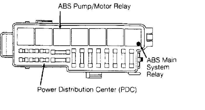
ABS main system relay is located on right side of engine compartment in Power Distribution Center (PDC). Turn ignition off. Remove cover from PDC. Locate and remove ABS main system relay from PDC. See Fig. 1. To install, reverse removal procedure.
92E22G3G
Fig. 1: Locating ABS System Relays Courtesy of Chrysler Corp.
ABS PUMP/MOTOR RELAY
Removal & Installation
ABS pump/motor relay is located on right side of engine compartment in Power Distribution Center (PDC). Turn ignition off. Remove cover from PDC. Locate and remove ABS pump/motor relay from PDC. See Fig. 1. To install, reverse removal procedure.
CONTROLLER ANTI-LOCK BRAKE (CAB)
Removal & Installation (Cherokee)
Turn ignition off. CAB is located under instrument panel to right of steering column. Remove screws attaching CAB mounting bracket to vehicle. Disconnect CAB electrical connector. Disconnect security alarm module electrical connector. Security alarm module is mounted on opposite side of mounting bracket. Remove CAB and mounting bracket. See Fig. 2. To install, reverse removal procedure. If installing a new CAB, transfer mounting bracket to new CAB.
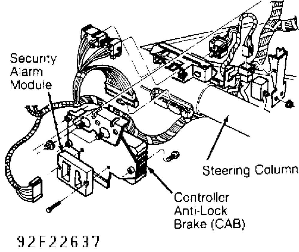
Fig. 2: Locating Controller Anti-Lock Brake (CAB) Courtesy of Chrysler Corp.
CAUTION: DO NOT force CAB electrical connector onto CAB. CAB pins are easily damaged.
Removal & Installation (Grand Cherokee & Grand Wagoneer) Turn ignition off. Disconnect negative battery cable. CAB is located on driver-side inner fender panel. Remove screws attaching CAB to fender panel bracket. Remove CAB from bracket for access to CAB electrical connector. Release strap securing harness connector to CAB. Tilt CAB electrical connector upward to disengage. Slide CAB electrical connector from retaining tangs. Remove CAB from vehicle. To install, reverse removal procedure.
Removal & Installation (Wrangler)
Turn
ignition off. Disconnect negative battery cable. CAB
is located
above heater/air conditioning plenum housing in line with
the
glove box. Remove bolts and nuts securing CAB to dash panel.
Bolts
and nuts are accessible from the engine compartment and are
located to
the right of the battery.
On models
with air conditioning, remove air conditioning
fascia panel and
ducts to access CAB harness connector. Release strap
securing
harness connector to CAB. Tilt CAB electrical connector
outward
to disengage. Slide CAB electrical connector from retaining
tangs.
Remove CAB from vehicle. To install, reverse removal procedure.
FRONT WHEEL SPEED SENSOR
Removal & Installation
Turn
ignition off. Raise and support vehicle. Remove wheel
and tire
assembly. Clean area surrounding wheel speed sensor prior
to
removal. Remove bolt attaching wheel speed sensor to steering
knuckle.
Unseat
grommet retaining wheel speed sensor wire in wheel
well panel.
Disconnect wheel speed sensor electrical connector in
engine
compartment. Disconnect wheel speed sensor wire harness from
clips
on body, chassis, and steering knuckle. Remove wheel speed
sensor
from vehicle.
To
install, reverse removal procedure. Remove all kinks
and twists
from wheel speed sensor wire harness. Ensure wheel speed
sensor
wire harness is installed in clips on body, chassis and
steering
knuckle. Use Loctite on wheel speed sensor mounting bolt.
Tighten
wheel speed sensor bolt to specification. See
TORQUE
SPECIFICATIONS table. Air gap is not adjustable. Air gap should
be
.040" (1.3 mm). If
air gap is not to specification, replacement of
wheel speed
sensor and/or tone wheel may be necessary.
"G" SWITCH
Removal & Installation (Except Wrangler)
Turn ignition off. Disconnect negative battery cable. Tilt rear seat assembly forward to access "G" switch. Disconnect "G" switch electrical connector. Remove "G" switch mounting bolts. Remove "G" switch. See Fig. 3. To install, reverse removal procedure. Ensure arrow on top of "G" switch is facing toward front of vehicle.
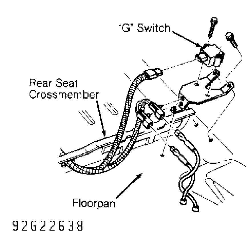
Fig. 3: Locating "G" Switch (Typical Except Wrangler) Courtesy of Chrysler Corp.
Removal & Installation (Wrangler)
Turn ignition off. Disconnect negative battery cable. Move driver’s seat assembly forward or rearward to access "G" switch. Disconnect "G" switch electrical connector. Remove "G" switch mounting bracket-to-floorpan screws. Remove "G" switch from mounting bracket. See Fig. 4. To install, reverse removal procedure. Ensure arrow on top of "G" switch is facing toward front of vehicle.
CCD Connector
"G- Switch
ition
Fig. 4: Locating "G" Switch & CCD Connector (Wrangler) Courtesy of Chrysler Corp.
HYDRAULIC CONTROL UNIT (HCU)
Removal & Installation
Turn
ignition off. Disconnect negative battery cable.
Disconnect pedal
travel sensor electrical connector. Remove air
cleaner and hoses.
On Grand Cherokee and Grand Wagoneer,
remove
windshield washer reservoir. On all models, position a
small drain
container under master cylinder reservoir hoses.
Disconnect master
cylinder reservoir
hoses at HCU and drain fluid into container. See
Fig.
5. Discard fluid. Disconnect HCU
electrical connectors.
On
Grand Cherokee and Grand Wagoneer, remove combination
valve. On
all models, identify HCU brakelines for reassembly
reference.
Disconnect brakelines from HCU. Remove bolt and nuts
attaching
HCU mounting bracket to inner fender panel. Remove
HCU from
vehicle. To install, reverse
removal procedure. Bleed brake system.
See
BLEEDING BRAKE SYSTEM.
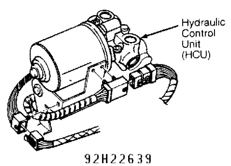
Fig. 5: Locating Hydraulic Control Unit (HCU) Courtesy of Chrysler Corp.
PEDAL TRAVEL SENSOR
Removal & Installation
Turn ignition off. Disconnect pedal travel sensor electrical connector. Pump brake pedal to exhaust all vacuum from vacuum booster. Unseat pedal travel sensor retaining ring. Remove pedal travel sensor from vacuum booster. See Fig. 6. To install, reverse removal procedure. Ensure color dot on face of vacuum booster matches color of plunger tip. If colors are different, replace plunger tip to match color dot on vacuum booster.
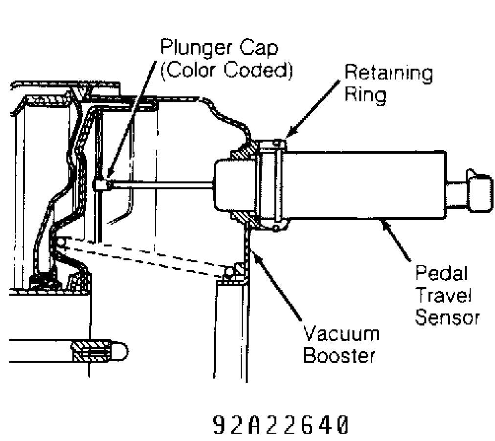
Fig. 6: Locating Pedal Travel Sensor Courtesy of Chrysler Corp.
REAR WHEEL SPEED SENSOR
Removal
Turn
ignition off. Raise and fold rear seat to access rear
wheel speed
sensor connectors. Disconnect rear wheel speed sensor
electrical
connector. Push rear wheel speed sensor grommet and wire
harness
through floorpan on vehicle.
Raise and
support vehicle. Remove wheel and brake drum.
Remove clips
attaching rear wheel speed sensor wire harness to
brakelines.
Unseat rear wheel speed sensor grommet from brake backing
plate.
Remove rear wheel speed sensor mounting bolt. Push rear wheel
speed
sensor through grommet opening in backing plate. Remove rear
wheel
speed sensor from vehicle.
Installation
If
original wheel speed sensor is being installed, go to
step
3). If a NEW wheel speed sensor is being
installed, position
wheel speed sensor until cardboard spacer
contacts tone wheel.
Use
Loctite on the wheel speed sensor mounting bolt.
Tighten wheel
speed sensor mounting bolt to specification. Refer to
TORQUE SPECIFICATIONS. Spin rear axle by hand until cardboard spacer is peeled from sensor face. Air gap adjustment should be correct. Using a brass feeler gauge, check air gap adjustment. Air gap should be .043" (1.1 mm). If air gap is not correct, adjust as necessary. Go to step 4).
Remove
any remaining pieces of cardboard from sensor face.
Install
wheel speed sensor. Using a brass feeler gauge, adjust air
gap.
Air gap should be .043" (1.1 mm).
Use Loctite on wheel speed
sensor mounting
bolt. Tighten wheel speed sensor mounting bolt to
specification.
See TORQUE SPECIFICATIONS.
Remove
all kinks and twists from wheel speed sensor wire
harness.
Ensure wheel speed sensor wire harness is installed in clips
on
brakelines. To complete installation,
reverse removal procedure.
DIAGNOSIS & TESTING
NOTE: DRB-II and appropriate cartridge are necessary for
diagnosing ABS.
WARNING LIGHTS
Amber ABS Warning Light
After engine start-up, ABS warning light glows as part of a self-check feature. ABS warning light normally will light for 2-3 seconds and then go out. If ABS warning light remains illuminated after engine start-up, diagnosis will be necessary to determine which component or circuit is malfunctioning.
Red BRAKE Warning Light
With ignition on, Red BRAKE warning light will glow when low brake fluid level is detected or parking brake switch is closed. BRAKE warning light normally indicates a hydraulic or mechanical failure is present.
PRE-DIAGNOSTIC INSPECTION
Check
master cylinder reservoir for correct fluid level.
Inspect
Hydraulic Control Unit (HCU) for leakage and wiring damage.
Check
caliper piston for activation and release. Check all brakes
to
verify no drag exists.
Check
speed sensors for correct mounting and alignment.
Inspect wire
harness for correct routing. Ensure connectors are not
damaged
and have good contact.
Verify
all wheel bearings are not worn or causing wheel
wobble.
Ensure all tires are in good condition and properly inflated.
After
performing pre-diagnostic inspection, perform TEST-1A
under
SELF-DIAGNOSTIC TESTS using
DRB-II. See Figs. 4, 7 and 8.
 T
T
CCD Connector Location
92B22G41
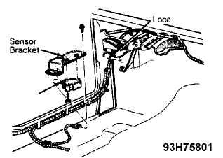
Fig. 7: Locating CCD Connector (Cherokee) Courtesy of Chrysler Corp.
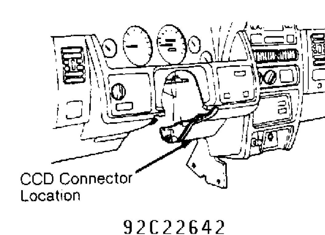
Fig. 8: Locating CCD Connector (Grand Cherokee & Grand Wagoneer) Courtesy of Chrysler Corp.
INTERMITTENTS
Most intermittent problems are caused by faulty electrical
connections
or wiring; however, a sticking relay or solenoid can cause
a
failure.
When intermittent failure is encountered, check for fault
messages stored in CAB. If fault messages are found, inspect related
components
and circuitry for poor connections. If no trouble codes are
found,
inspect suspect circuits as follows:
Check
for poor mating of connector halves, or terminals not
fully
seated in connector body (backed-out).
Check for
improperly formed or damaged terminals. Carefully
reform all
connector terminals of problem circuit to increase
contact
tension.
Check for poor terminal-to-wire connection.
Check for hydraulic system leaks.
CLEARING FAULT MESSAGES
DRB-II
Using DRB-II, select ADJUSTMENTS. Press "1" (ERASE FAULTS key). Press ENTER key. DRB-II will display ERASE FAULTS ARE YOU SURE? (ENTER TO ERASE). Press ENTER key. DRB-II will display ERASE FAULTS TURN KEY OFF. Turn ignition off. Turn ignition on. DRB-II will display
ERASE FAULTS FAULTS ERASED. Faults are now erased.
Ignition Cycle Default
If no fault codes occur for 50 driving cycles, any existing fault messages will be cleared from CAB memory. A drive cycle occurs when ignition is turned on and vehicle is driven faster than 10 MPH.
CONNECTOR IDENTIFICATION
CONNECTOR IDENTIFICATION DIRECTORY TABLE
Connector
Figure
ABS Disconnect Connector 9
ABS Main System Relay Socket Connector 10
ABS Pump/Motor Relay Socket Connector 11
Controller Anti-Lock Brake (CAB) Connector 12
"G" Switch Connector 13
Hydraulic Control Unit (HCU) Connector 14
Pump/Motor Connector 15
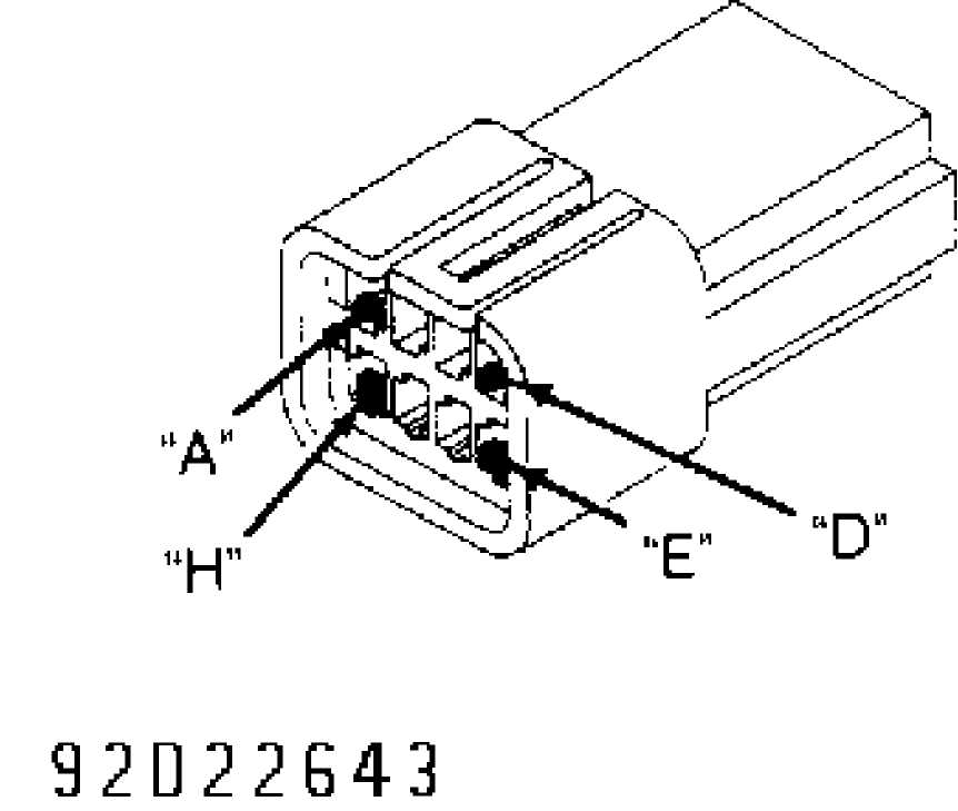
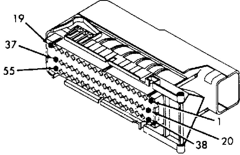
Fig. 9: Identifying ABS Disconnect Connector Terminals Courtesy of Chrysler Corp.
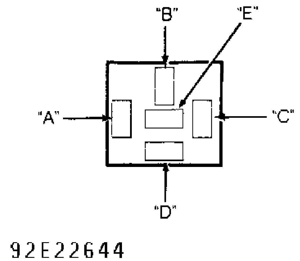
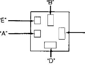
Fig. 10: Identifying ABS Main System Relay Connector Terminals Courtesy of Chrysler Corp.
92F22G45
Fig. 11: Identifying ABS Pump/Motor Relay Connector Terminals Courtesy of Chrysler Corp.
92G22G4G
Fig. 12: Controller Anti-Lock Brake (CAB) Connector Terminal ID Courtesy of Chrysler Corp.
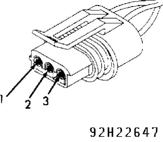
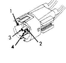
Fig. 13: Identifying "G" Switch Connector Terminals Courtesy of Chrysler Corp.
 92
122648
92
122648
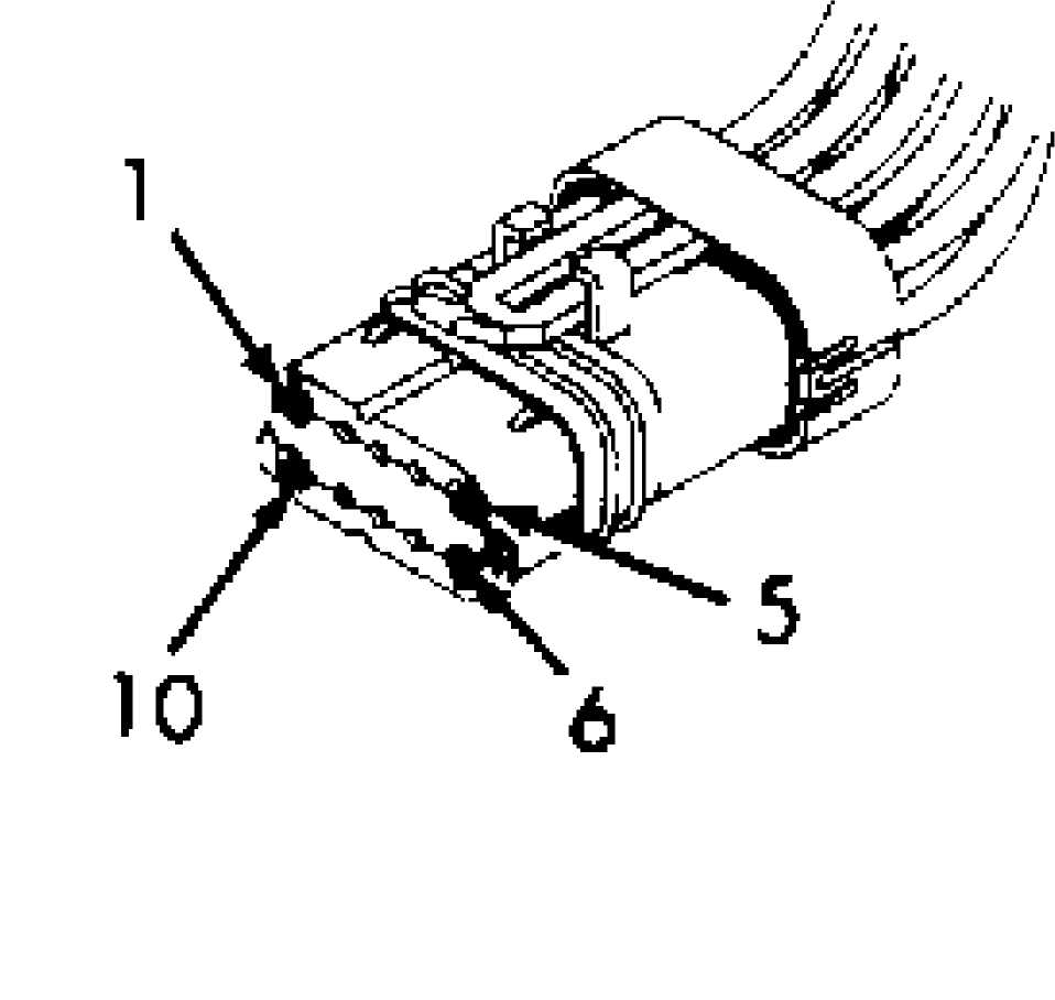
Fig. 14: Hydraulic Control Unit (HCU) Connector Terminal ID Courtesy of Chrysler Corp.
92J22G49
Fig. 15: Identifying Pump/Motor Connector Terminals Courtesy of Chrysler Corp.
SELF-DIAGNOSTIC TESTS
NOTE: Connector and terminal identification illustrations in following tests are provided courtesy of Chrysler Corp.
NOTE: For connector terminal identification in following tests,
see CONNECTOR IDENTIFICATION under DIAGNOSIS & TESTING. For wire color and terminal identification, see WIRING DIAGRAMS.
TEST 1A
READING FAULT MESSAGES
Using DRB-II, read fault messages and perform appropriate test listed in FAULT MESSAGES table. If DRB-II displays NO RESPONSE message, perform TEST 23A. If other DRB-II related communication problems exist, see VEHICLE COMMUNICATIONS article in ENGINE PERFORMANCE. If multiple fault messages are present, fault repairs must be performed in order in which they are displayed. If no fault messages are present, perform VERIFICATION TEST VER-1A.
FAULT MESSAGES TABLE
Fault Message Perform Test
CONTROLLER FAILURE 2A
"G" SWITCH NOT PROCESSABLE 3A
HYDRAULIC FAILURE 4A
LEFT FRONT INLET VALVE 5A
LEFT FRONT OUTLET VALVE 6A
LEFT FRONT SENSOR CIRCUIT FAILURE 7A
LEFT FRONT SENSOR CONTINUITYK25 MPH 7A
LEFT FRONT SENSOR CONTINUITYJ25 MPH 7A
LEFT FRONT SENSOR SIGNAL MISSING 7A
LEFT FRONT WHEEL SPEED COMPARISON 7A
REAR INLET VALVE 9A
REAR OUTLET VALVE 10A
LEFT REAR SENSOR CIRCUIT FAILURE 11A
LEFT REAR SENSOR CONTINUITYK25 MPH 11A
LEFT REAR SENSOR CONTINUITYJ25 MPH 11A
LEFT REAR SENSOR SIGNAL MISSING 11A
LEFT REAR WHEEL SPEED COMPARISON 11A
MAIN RELAY/POWER CIRCUIT FAILURE 13A
PEDAL TRAVEL SENSOR CIRCUIT 14A
PUMP MOTOR CIRCUIT NOT WORKING PROPERLY 15A
RIGHT FRONT INLET VALVE 16A
RIGHT FRONT OUTLET VALVE 17A
RIGHT FRONT CIRCUIT FAILURE 18A
RIGHT FRONT SENSOR CONTINUITYK25 MPH 18A
RIGHT FRONT SENSOR CONTINUITYJ25 MPH 18A
RIGHT FRONT REAR SENSOR SIGNAL MISSING 18A
RIGHT FRONT WHEEL SPEED COMPARISON 18A
RIGHT REAR SENSOR CIRCUIT FAILURE 20A
RIGHT REAR SENSOR CONTINUITYK25 MPH 20A
RIGHT REAR SENSOR CONTINUITYJ25 MPH 20A
RIGHT REAR SENSOR SIGNAL MISSING 20A
RIGHT REAR WHEEL SPEED COMPARISON 2 0A
ABS WARNING LAMP ILLUMINATION PROBLEM 22A
NO RESPONSE 23A
TEST 2A
CONTROLLER FAILURE
If DRB-II displays CONTROLLER FAILURE, replace Controller Anti-Lock Brake (CAB). Perform VERIFICATION TEST VER-1A.
TEST 3A
"G" SWITCH NOT PROCESSABLE
Ensure "G"
switch sensor assembly is properly installed.
If not properly
installed, repair as necessary and perform
VERIFICATION TEST
VER-1A. If "G" switch is properly installed, turn
ignition
off. Disconnect and inspect CAB 55-pin connector and "G"
switch
sensor 3-pin connector. Repair connectors as necessary.
Turn
ignition on. With DRB-II in voltmeter mode, probe "G"
switch
connector terminals individually. If voltage is present,
repair
short to voltage in that "G" switch circuit.
Perform VERIFICATION TEST
VER-1A. If voltage is not present at
any terminals, go to next step.
Turn
ignition off. With DRB-II in ohmmeter mode, probe "G"
switch
connector terminals individually with remaining lead connected
to
chassis ground. If resistance at any terminal is less than 5
ohms,
repair short
to ground in that circuit. Perform VERIFICATION TEST VER-
1A.
If
resistance at each terminal is more than 5 ohms,
connect
jumper wire between ground and "G" switch terminals No.
1-3.
Check for continuity to ground on
CAB terminals No. 25, 26 and 43.
If
continuity to
ground does not exist, repair open in that circuit.
Perform
VERIFICATION TEST VER-1A. If continuity to ground exists,
replace
CAB. Perform VERIFICATION TEST VER-1A.
TEST 4A
HYDRAULIC FAILURE
Inspect
brake system for hydraulic leaks, and repair as
necessary. If
brake system is okay, using DRB-II, read fault messages.
If
DRB-II displays PUMP/MOTOR NOT WORKING PROPERLY, perform TEST
15A.
If DRB-II displays PEDAL TRAVEL SENSOR CIRCUIT, perform TEST
14A. If
DRB-II does not display PUMP/MOTOR NOT WORKING PROPERLY
or PEDAL
TRAVEL SENSOR CIRCUIT, using DRB-II, erase fault
messages.
Using
DRB-II, monitor read faults display for 4 minutes.
If
any fault messages are displayed, perform TEST 1A. If no
fault
messages are displayed, depress brake pedal and hold down
until
instructed to release it. Using
DRB-II, actuate hydraulic valve test.
Release
brake pedal.
If
brake pedal came back up, perform TEST 14A. If brake
pedal
dropped all the way to the floor or there were not 3
slight
drops in the brake pedal, perform TEST
4B. If the brake pedal did not
come
back up at end of test, replace pump/motor assembly. If the
brake
pedal did come back up at end of test, replace CAB. If CAB
has already
been replaced, replace HCU.
Perform VERIFICATION TEST VER-1A.
TEST 4B
HYDRAULIC FAILURE
Disconnect and inspect CAB 55-pin connector. Repair connector as necessary. Disconnect and inspect hydraulic unit 10-pin connector. Repair connector as necessary. If terminals of both connectors are not
pushed out, damaged or improperly wired, replace hydraulic control unit. Perform VERIFICATION TEST VER-1A.
TEST 5A
LEFT FRONT INLET VALVE
Disconnect
and inspect hydraulic unit 10-pin connector.
Repair connector as
necessary. Turn ignition on. With DRB-II in
voltmeter mode, probe
terminal No. 4 (White/Light Green wire)
of
hydraulic unit connector. If voltage is present, repair short
to
voltage in White/Light Green wire.
Perform VERIFICATION TEST VER-1A.
If
voltage is not present, turn ignition off. Disconnect
and inspect
CAB 55-pin connector. Repair connector as necessary. With
DRB-II
in ohmmeter mode, probe terminal No. 4 (White/Light
Green wire)
of hydraulic unit connector. If resistance is less
than 5 ohms, repair
short to ground in
White/Light Green wire.
If
resistance is more than 5 ohms, check
resistance of
White/Light Green wire
between terminals No. 20 of CAB connector
and
No. 4 of
hydraulic unit connector using an external ohmmeter. If
resistance
is more than 5 ohms, repair open in
White/Light Green wire.
Perform VERIFICATION TEST VER-1A.
If
resistance is less than 5 ohms, measure
resistance of
left front inlet valve.
If resistance is 5-8 ohms, replace
CAB.
Perform VERIFICATION TEST VER-1A. If resistance is not 5-8
ohms,
replace hydraulic control unit. Perform
VERIFICATION TEST VER-1A.
TEST 6A
LEFT FRONT OUTLET VALVE
Disconnect
and inspect hydraulic unit 10-pin connector.
Repair
connector as necessary. Turn ignition on. With DRB-II in
voltmeter
mode, probe terminal No. 9 (Dark
Green/Black wire) of
hydraulic unit connector. If voltage is
present, repair short to
voltage in
Dark Green/Black wire. Perform VERIFICATION TEST VER-1A.
If
voltage is not present, turn ignition off. Disconnect
and inspect
CAB 55-pin connector. Repair connector as necessary. With
DRB-II
in ohmmeter mode, probe terminal No. 9 (Dark
Green/Black wire)
of hydraulic unit
connector. If resistance is less than 5 ohms,
repair
short to ground in Dark Green/Black wire.
If
resistance is more than 5 ohms, check
resistance of
Dark Green/Black wire
between terminals No. 2 of CAB connector
and No.
9 of hydraulic unit connector
using an external ohmmeter. If
resistance is more than 5
ohms, repair open in Dark Green/Black
wire.
Perform VERIFICATION TEST VER-1A.
If
resistance is less than 5 ohms, measure
resistance of
left front outlet valve. If resistance is not 3-5
ohms, replace
hydraulic control unit. Perform
VERIFICATION TEST VER-1A. If
resistance
is 3-5 ohms, replace CAB. Perform
VERIFICATION TEST VER-1A.
TEST 7A
LEFT FRONT SENSOR CIRCUIT FAILURE
1) Using DRB-II, read and record all speed sensor fault messages. If DRB-II does not display LEFT FRONT SENSOR CIRCUIT FAILURE, perform TEST 8A. If DRB-II displays LEFT FRONT SENSOR CIRCUIT FAILURE, inspect left front wheel speed sensor for damage. If sensor is damaged, repair or replace sensor as necessary. Perform
VERIFICATION TEST VER-1A. If sensor is okay, turn ignition off.
Disconnect
and inspect CAB 55-pin connector. Repair
connector as necessary.
Turn ignition on. With DRB-II in voltmeter
mode,
probe terminal No. 48 (Red wire) of CAB
connector. If voltage is
present,
repair short to battery in Red wire. Perform VERIFICATION
TEST
VER-1A.
If
voltage is not present, turn ignition off. With DRB-II
in
ohmmeter mode, probe terminal No. 48 (Red
wire) of CAB connector.
If resistance
is less than 5 ohms, repair short to
ground in Red wire.
Perform
VERIFICATION TEST VER-1A. If resistance is more than 5
ohms,
go to next
step.
Using
an external ohmmeter, check resistance between
terminal
No. 48 (Red wire) and No. 30
(Red/Dark Blue wire) of CAB
connector.
If resistance is 900-1300 ohms, replace
CAB. Perform
VERIFICATION TEST VER-1A. If resistance is not
900-1300 ohms,
disconnect and inspect
left front wheel speed sensor connector.
Using
an external ohmmeter, check resistance between left
wheel speed
sensor connector terminals. If resistance is not 900-1300
ohms,
replace wheel speed sensor. Perform VERIFICATION TEST VER-1A.
If
resistance is 900-1300 ohms,
check resistance of Red wire between
terminal No. 48 of
CAB connector and No. 1 of left front
wheel speed
sensor connector using an
external ohmmeter.
If
resistance is more than 5 ohms, repair
open Red wire.
Perform VERIFICATION TEST VER-1A. If resistance is
less than 5 ohms,
repair
open Red/Dark Blue wire. Perform VERIFICATION TEST VER-1A.
TEST 8A
LEFT FRONT SENSOR
Inspect
left front wheel speed sensor for damage. Repair
or replace
sensor as necessary. Perform VERIFICATION TEST VER-1A. If
sensor
is okay, check left front sensor tone (pulse) ring for
damage.
Repair or replace tone ring as necessary. Perform
VERIFICATION TEST
VER-1A. If tone ring is okay, inspect left
front wheel speed sensor
wiring harness for damage.
Repair or replace wiring as necessary. Perform
VERIFICATION TEST VER-1A. If wiring harness is okay, disconnect and inspect left front wheel speed sensor connector. Repair connector as necessary. Using an external ohmmeter, check resistance between left front wheel speed sensor connector terminals.
3) If
resistance is not 900-1300 ohms, replace
wheel speed
sensor. Perform VERIFICATION TEST VER-1A. If
resistance is 900-1300
ohms, replace
CAB. Perform VERIFICATION TEST VER-1A.
NOTE: If excessive axle deflection occurs on extremely bumpy
surfaces or during off road use, it is possible for a wheel speed sensor to set a code.
TEST 9A
REAR INLET VALVE
Disconnect
and inspect hydraulic unit 10-pin connector.
Repair connector as
necessary. Turn ignition on. With DRB-II in
voltmeter mode, probe
terminal No. 4 (White/Black wire on
Cherokee and
Wrangler or White/Red wire on Grand Cherokee and
Grand Wagoneer) of
hydraulic unit connector. If voltage is
present, repair short to
voltage in White/Black or White/Red
wire. Perform VERIFICATION TEST
VER-1A.
If voltage is not present, turn ignition off. Disconnect
and inspect CAB 55-pin connector. Repair connector as necessary. With DRB-II in ohmmeter mode, probe terminal No. 4 of hydraulic unit connector. If resistance is less than 5 ohms, repair short to ground in White/Black or White/Red wire. Perform VERIFICATION TEST VER-1A.
If
resistance is less than 5 ohms, check
resistance of
between terminal No. 54
of CAB connector and No. 4 of
hydraulic unit
connector using an
external ohmmeter. If resistance is more than 5
ohms,
repair open in White/Black or White/Red wire. Perform
VERIFICATION
TEST VER-1A.
Using
an external ohmmeter, check resistance between
terminals
No. 4 and 5 of
hydraulic control unit pigtail connector. If
resistance
is not 5-8 ohms, replace hydraulic control
unit. Perform
VERIFICATION TEST VER-1A.
If resistance is 5-8 ohms, replace
CAB.
Perform VERIFICATION TEST VER-1A.
TEST10A
REAR OUTLET VALVE
Disconnect
and inspect hydraulic unit 10-pin connector.
Repair
connector as necessary. Turn ignition on. With DRB-II in
voltmeter
mode, probe terminal No. 7 (Dark
Green/Orange wire) of
hydraulic unit connector. If voltage is
present, repair short to
voltage in
Dark Green/Orange wire. Perform VERIFICATION TEST VER-1A.
If
voltage is not present, turn ignition off. Disconnect
and
inspect CAB 55-pin connector. Repair connector as necessary.
With
DRB-II in ohmmeter mode, probe
terminal No. 7 (Dark Green/Orange wire)
of
hydraulic unit connector. If resistance is less than 5 ohms,
repair
short to ground in Dark Green/Orange wire.
If
resistance is more than 5 ohms, check
resistance of
Dark Green/Orange wire between terminal No. 36
of CAB connector and
No. 7 of
hydraulic unit connector using an external ohmmeter. If
resistance
is more than 5 ohms, repair open Dark
Green/Orange wire.
Perform VERIFICATION
TEST VER-1A. If resistance is less than 5 ohms,
go
to next step.
Using
an external ohmmeter, check resistance between
terminals No. 7
and 10 of hydraulic
control unit connector. If
resistance
is not 3-5 ohms, replace hydraulic control
unit. Perform
VERIFICATION TEST VER-1A. If resistance is 3-5
ohms, replace CAB.
Perform
VERIFICATION TEST VER-1A.
TEST 11A
LEFT REAR SENSOR CIRCUIT FAILURE
1) Using DRB-II, read and record all speed sensor fault
messages. If DRB-II does not display LEFT REAR SENSOR CIRCUIT FAILURE, perform TEST 12A. If DRB-II displays LEFT REAR SENSOR CIRCUIT FAILURE, inspect left rear wheel speed sensor for damage. If sensor is damaged, repair or replace sensor as necessary. Perform VERIFICATION TEST VER-1A. If sensor is okay, turn ignition off.
Disconnect
and inspect CAB 55-pin connector. Repair
connector as necessary.
Turn ignition on. With DRB-II in voltmeter
mode,
probe terminal No. 46 (Light Green wire)
of CAB connector. If
voltage is present, perform TEST 11B.
If
voltage is not present, turn ignition off. With DRB-II
in
ohmmeter mode, probe terminal No. 46 (Light
Green wire) of CAB
connector. If resistance is less than 5
ohms, perform TEST 11C. If
resistance is more
than 5 ohms, using an external ohmmeter,
check
resistance between terminal No.
46 (Light Green wire) and No. 28
(Light
Green/Dark Blue wire) of CAB connector.
If
resistance is 900-1300 ohms, replace CAB.
Perform
VERIFICATION TEST VER-1A. If
resistance is not 900-1300 ohms,
disconnect
and inspect left rear wheel speed sensor connector. Using
an
external ohmmeter, check resistance between left rear wheel
speed
sensor connector terminals. If resistance is not 900-1300
ohms,
replace wheel speed sensor. Perform
VERIFICATION TEST VER-1A.
If
resistance is 900-1300 ohms, connect a
jumper wire
between terminal No. 46
(Light Green wire) of CAB connector and
ground.
With DRB-II in ohmmeter mode, probe Light Green wire of left
rear
wheel speed sensor connector. If resistance is more than 5
ohms,
perform TEST
11D. If resistance is less than 5 ohms,
perform TEST 11E.
TEST11B
LEFT REAR SENSOR CIRCUIT FAILURE
On
Cherokee and Wrangler, repair short to battery voltage
in Light
Green wire. Perform VERIFICATION TEST VER-1A. On Grand
Cherokee
and Grand Wagoneer, disconnect and inspect Black ABS
8-pin
disconnect connector. Connector is located behind left side
kick
panel. Repair connector as necessary. With DRB-II in
voltmeter mode,
probe Light Green wire of ABS disconnect
connector.
If voltage
is not present, repair short to battery voltage
in Light Green
wire between wheel speed sensor and CAB disconnect
connector.
Perform VERIFICATION TEST VER-1A. If voltage is present,
repair
short to battery voltage in Light Green wire between ABS
disconnect
connector and CAB 55-pin connector. Perform VERIFICATION
TEST
VER-1A.
TEST 11C
LEFT REAR SENSOR CIRCUIT FAILURE
On
Cherokee and Wrangler, repair short to ground in Light
Green
wire. Perform VERIFICATION TEST VER-1A. On Grand Cherokee and
Grand
Wagoneer, disconnect and inspect Black CAB 8-pin
disconnect
connector. Connector is located behind left side kick
panel. Repair
connector as necessary. With DRB-II in ohmmeter
mode, probe Light
Green wire of ABS disconnect connector.
If
resistance is more than 5 ohms, repair
short to ground
in Light Green wire between wheel speed sensor
and ABS disconnect
connector. Perform
VERIFICATION TEST VER-1A. If resistance is less
than 5
ohms, repair short to ground in Light Green wire
between ABS
disconnect connector and CAB 55-pin connector.
Perform VERIFICATION
TEST VER-1A.
TEST11D
LEFT REAR SENSOR CIRCUIT FAILURE
On
Cherokee and Wrangler, repair open in Light Green wire.
Perform
VERIFICATION TEST VER-1A. On Grand Cherokee and Grand
Wagoneer,
disconnect and inspect Black CAB 8-pin disconnect
connector.
Connector is located behind left side kick panel.
Repair connector as
necessary. With DRB-II in ohmmeter mode,
probe Light Green wire of ABS
disconnect connector.
If
resistance is less than 5 ohms, repair
open in Light
Green wire between wheel speed sensor and ABS
disconnect connector.
Perform VERIFICATION TEST VER-1A. If
resistance is more than 5 ohms,
repair
open in Light Green wire between ABS disconnect connector and
CAB 55-pin connector. Perform VERIFICATION TEST VER-1A.
TEST11E
LEFT REAR SENSOR CIRCUIT FAILURE
On
Cherokee and Wrangler, repair open in Light Green/Dark
Blue
wire. Perform VERIFICATION TEST VER-1A. On Grand Cherokee and
Grand
Wagoneer, disconnect and inspect Black ABS 8-pin
disconnect
connector. Connector is located behind left side kick
panel. Repair
connector as necessary.
Connect a jumper wire between terminal No. 28
(Light
Green/Dark Blue wire) of CAB connector and ground. With DRB-II
in
ohmmeter mode, probe Light Green/Dark Blue wire of ABS
disconnect
connector.
If
resistance is less than 5 ohms, repair
open in Light
Green/Dark Blue wire
between wheel speed sensor and ABS disconnect
connector. Perform
VERIFICATION TEST VER-1A. If resistance is more
than 5
ohms, repair open in Light Green/Dark Blue wire
between ABS
disconnect connector and
CAB 55-pin connector. Perform VERIFICATION
TEST
VER-1A.
TEST12A
LEFT REAR SENSOR
Inspect
left rear wheel speed sensor. If speed sensor is
damaged,
contaminated or loose, repair or replace speed sensor as
necessary.
Perform VERIFICATION TEST VER-1A. If speed sensor is okay,
inspect
left rear tone (pulse) ring for damaged teeth or excessive
runout.
Runout should not exceed .003" (.08 mm).
Repair or replace
tone ring as necessary.
Perform VERIFICATION TEST VER-1A.
If
tone ring is okay, using a feeler gauge, check left
rear wheel
sensor-to-tone ring clearance. If clearance is not .036-.
050"
(.91-1.27 mm), repair as necessary. If clearance
is .036-.050" (.
91-1.27 mm),
inspect left rear wheel speed sensor inspect left front
wheel
speed sensor wiring harness for damage.
Repair
or replace wiring as necessary. If wiring harness
is okay,
disconnect and inspect left rear wheel speed sensor
connector.
Repair connector as necessary. Using an external ohmmeter,
check
resistance between left rear wheel speed sensor connector
terminals.
If
resistance is not 900-1300 ohms, replace
wheel speed
sensor. Perform VERIFICATION TEST VER-1A. If
resistance is 900-1300
ohms, replace
CAB. Perform VERIFICATION TEST VER-1A.
NOTE: If excessive axle deflection occurs on extremely bumpy
surfaces or during off road use, it is possible for a wheel speed sensor to set a code.
TEST 13A
MAIN RELAY/POWER CIRCUIT FAILURE
Check
ABS system fuse in Power Distribution Center (PDC).
If
fuse is not okay, perform TEST 13B. If fuse is okay, go to
next
step.
Check if
charging system is overcharging. If charging
system is operating
properly, go to next step. If charging system is
not operating
properly, repair as necessary. Perform VERIFICATION TEST
VER-1A.
Temporarily
replace ABS main relay with another 5-terminal
relay from PDC.
Using DRB-II, erase ABS fault messages. Cycle ignition
off and
on. Using DRB-II, read ABS fault messages. If MAIN
RELAY/POWER
CIRCUIT FAILURE message is displayed, go to next
step. If fault is not
displayed, replace ABS main relay. Perform
VERIFICATION TEST VER-1A.
Install
replacement 5-terminal relay back into PDC,
leaving
ABS main relay disconnected (removed). With
DRB-II in
voltmeter mode, probe fused battery feed Red/Dark Green
wire
(Red/Light Green wire on Grand Cherokee and Grand Wagoneer) at ABS main relay socket. If voltage is more than 9 volts, go to next step. If voltage is less than 9 volts, repair open Red/Dark Green wire
(Red/Light Green on Grand Cherokee and Grand Wagoneer) wire to ABS fuse in PDC. Perform VERIFICATION TEST VER-1A.
Turn
ignition off. Disconnect and inspect CAB 55-pin
connector. Repair
connector as necessary. Ensure ABS main relay is
still
disconnected. Using an external ohmmeter, check continuity of
Pink
(Pink/Dark Blue on Grand Cherokee and Grand Wagoneer) wire
between
CAB connector terminal No. 34 and ABS main
relay socket
terminal "C". If
resistance is less than 5 ohms, go to next
step. If
resistance is more than 5
ohms, repair open Pink (Pink/Dark Blue on
Grand
Cherokee and Grand Wagoneer) wire to ABS main relay.
Perform
VERIFICATION TEST VER-1A.
Check
continuity of Gray/Yellow wire between CAB connector
terminal
No. 3 and ABS main relay socket terminal
"B". If resistance
is less
than 5 ohms, go to next step. If
resistance is more than 5
ohms, repair
open Gray/Yellow wire to ABS main relay. Perform
VERIFICATION
TEST VER-1A.
Check
continuity of Gray/Yellow wire between CAB connector
terminal
No. 33 and ABS main relay socket terminal
"B". If resistance
is
less than 5 ohms, replace CAB. Perform
VERIFICATION TEST VER-1A. If
resistance
is more than 5 ohms, repair open
Gray/Yellow wire to ABS
main relay.
Perform VERIFICATION TEST VER-1A.
TEST13B
MAIN RELAY/POWER CIRCUIT FAILURE
Remove
ABS system fuse from Power Distribution Center
(PDC).
Remove ABS main relay from PDC, and inspect
connector. Repair
connector as
necessary. With DRB-II in ohmmeter mode, probe fused
battery feed
Red/Dark Green wire (Red/Light Green wire on Grand
Cherokee
and Grand Wagoneer or Red/Dark Blue wire on Wrangler) at ABS
main
relay socket. If resistance is less than 5 ohms,
repair Red/Dark
Green wire (Red/Light Green wire on Grand
Cherokee and Grand Wagoneer
or Red/Dark
Blue wire on Wrangler) for a short to ground. Perform
VERIFICATION
TEST VER-1A. If resistance is more than 5 ohms,
go to
next step.
Remove ABS pump/motor relay from PDC, and inspect
connector. Repair connector as necessary. Using an external ohmmeter, measure resistance of ABS pump/motor relay coil. See Fig. 16. If resistance is 35-65 ohms, go to next step. If resistance is not 35-65 ohms, replace ABS pump/motor relay. Perform VERIFICATION TEST VER-1A.
3) Disconnect
hydraulic control unit 10-pin connector. With
DRB-II
in ohmmeter mode, probe Gray/Yellow wire (Gray/Pink wire on
Grand
Cherokee and Grand Wagoneer) at ABS main relay socket terminal
"B".
If resistance is less than 5 ohms,
repair Gray/Yellow wire
(Gray/Pink wire
on Grand Cherokee and Grand Wagoneer) for a short to
ground. Perform VERIFICATION TEST VER-1A. If resistance is more than 5 ohms, go to next step.
4) Reconnect
all disconnected components. Install a new ABS
fuse
in PDC and cycle ignition off and on. Inspect ABS fuse in PDC.
If
fuse is okay (does not blow), perform
TEST 13C. If fuse is not okay
(blows), replace hydraulic control unit. Perform VERIFICATION TEST VER-1A.
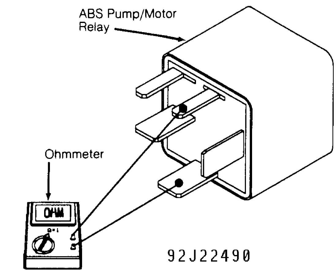
Fig. 16: Measuring ABS Pump/Motor Relay Resistance
TEST13C
MAIN RELAY/POWER CIRCUIT FAILURE
Ensure
DRB-II is NOT in TEVES ABS DIAGNOSTIC MODE. Road
test vehicle,
making several ABS stops. Inspect ABS fuse in PDC. If
fuse
is okay (does not blow), ABS system is
operating properly at this
time. Perform VERIFICATION TEST
VER-1A.
If fuse is
not okay (blows), inspect ABS wiring harness
for damage and
repair as necessary. Perform VERIFICATION TEST VER-1A.
If wiring
harness is okay, replace hydraulic control unit.
Perform
VERIFICATION TEST VER-1A.
TEST14A
PEDAL TRAVEL SENSOR CIRCUIT
Inspect
pedal travel sensor connector. Sensor is located
on right side of
brake booster. If connector is disconnected and/or
damaged,
repair connector as necessary and perform VERIFICATION TEST
VER-1A.
If connector is properly connected and NOT damaged, go to next
step.
Turn
ignition off. Disconnect and inspect CAB 55-pin
connector. Repair
connector as necessary. Turn ignition on. Disconnect
and inspect
pedal travel sensor connector. Repair connector as
necessary.
With DRB-II in voltmeter mode, probe Gray/Light Blue wire
at
sensor connector. If no voltage is present, go to next step.
If
voltage is present, repair Gray/Light Blue wire for a short to
battery
voltage. Perform VERIFICATION TEST VER-1A.
Turn
ignition off. With DRB-II in ohmmeter mode, probe
Gray/Light Blue
wire at pedal travel sensor connector. If resistance
is less than
5 ohms, repair Gray/Light Blue wire for a
short to
ground. Perform VERIFICATION
TEST VER-1A. If resistance is more than 5
ohms,
go to next step.
Using
an external ohmmeter, measure resistance between CAB
connector
terminal No. 16 and pedal travel sensor
connector Gray/Light
Blue wire. If
resistance is less than 5 ohms, go to next
step. If
resistance is more than 5 ohms,
repair open Gray/Light Blue wire to
pedal travel sensor. Perform
VERIFICATION TEST VER-1A.
Using
an external ohmmeter, measure resistance between CAB
connector
terminal No. 41 and pedal travel sensor
connector Red/Black
wire. If resistance is less than 5
ohms, go to next step. If
resistance is more
than 5 ohms, repair open Red/Black wire to
pedal
travel sensor. Perform VERIFICATION TEST VER-1A.
Remove
pedal travel sensor from brake booster. Check if
sensor
plunger cap color matches color dot on booster (near sensor).
If
colors match, go to next step. If colors do not match, replace
pedal
travel sensor. Perform VERIFICATION TEST VER-1A.
Using an
external ohmmeter, measure resistance of pedal
travel sensor
while slowly depressing sensor plunger. If sensor
resistance is
as specified, replace CAB. See PEDAL TRAVEL SENSOR
RESISTANCE
table. Perform VERIFICATION TEST VER-1A. If sensor
resistance is
not as specified, replace pedal travel sensor. Perform
VERIFICATION
TEST VER-1A.
PEDAL TRAVEL SENSOR RESISTANCE TABLE
Plunger Position Ohms
Step 1 (Rest) 236-262
Step 2 414-458
Step 3 534-592
Step 4 655-725
Step 5 776-858
Step 6 980-1084
Step 7 Infinity
TEST15A
PUMP MOTOR CIRCUIT NOT WORKING PROPERLY
1) Inspect
ABS pump/motor fuse from Power Distribution Center
(PDC).
If fuse is okay, go to next step. If fuse is not
okay (blown),
perform TEST 15B.
2) Remove ABS pump/motor relay from PDC, and inspect
connector. Repair connector as necessary. With DRB-II in voltmeter mode, probe Red/Dark Green wire (Red/Dark Blue wire on Grand Cherokee and Grand Wagoneer or Red/Brown wire on Wrangler) at ABS pump/motor relay socket terminal "B". If voltage is more than 9 volts, go to next step. If voltage is less than 9 volts, repair open Red/Dark Green wire (Red/Dark Blue wire on Grand Cherokee and Grand Wagoneer or Red/Brown wire on Wrangler) to ABS pump/motor relay.
Connect a
jumper wire between Red/Dark Green wire and
Tan/Black wire
(Brown/White wire and Red/Dark Blue wire on Grand
Cherokee and
Grand Wagoneer or Tan wire and Red/Brown wire on
Wrangler) at ABS
pump/motor relay socket terminals "B" and "D".
Turn
ignition on. Inspect ABS pump/motor fuse. If fuse is okay
(does not
blow), go to next step. If fuse is not okay (blows),
perform TEST 15B.
Listen for
ABS pump/motor operation. If ABS pump/motor is
running, go to
next step. If ABS pump/motor is not running, perform
TEST 15C.
Turn
ignition off. Remove jumper wire. With DRB-II in
ohmmeter mode,
probe Gray/Yellow wire (Gray/Pink wire on Grand
Cherokee and
Grand Wagoneer) at ABS pump/motor relay socket. If
resistance
is less than 5 ohms, go to next step. If
resistance is more
than 5 ohms,
repair open Gray/Yellow wire (Gray/Pink wire on Grand
Cherokee
and Grand Wagoneer) wire between ABS pump/motor relay socket
and
ABS main relay. Perform VERIFICATION TEST VER-1A.
Using
an external ohmmeter, measure resistance of ABS
pump/motor relay
coil terminals No. 85 and 86. See
Fig. 16. If
resistance
is 35-65 ohms, go to next step. If
resistance is not 35-65
ohms, replace
ABS pump/motor relay. Perform VERIFICATION TEST VER-1A.
Disconnect
and inspect CAB 55-pin connector. Repair
connector as necessary.
Turn ignition on. With DRB-II in voltmeter
mode, probe Gray wire
at ABS pump/motor relay socket. If no voltage is
present, go to
next step. If any voltage is present, repair Gray wire
for a
short to battery voltage. Perform VERIFICATION TEST VER-1A.
Turn
ignition off. With DRB-II in ohmmeter mode, probe
Gray
wire at ABS pump/motor relay socket. If resistance is less than
5
ohms, repair Gray wire for a short to
ground. Perform VERIFICATION
TEST
VER-1A. If resistance is more than 5 ohms,
go to next step.
Using
an external ohmmeter, measure resistance between CAB
connector
terminal No. 15 and ABS pump/motor relay
socket Gray wire.
If resistance is less
than 5 ohms, go to next step. If
resistance is
more than 5 ohms, repair
open Gray wire to relay socket. Perform
VERIFICATION
TEST VER-1A.
Turn
ignition off. Reinstall ABS pump/motor relay in PDC.
Apply
battery voltage to CAB connector terminal No. 15, and
go to next
step.
Ensure
ignition is off. With DRB-II in voltmeter mode,
probe
Tan/Black wire (Brown/White wire on Grand Cherokee and
Grand
Wagoneer or Tan wire on Wrangler) at ABS pump/motor 4-pin
harness
connector. If voltage is more than 9 volts,
perform TEST 15D. If
voltage is less
than 9 volts, replace ABS pump/motor
relay. Perform
VERIFICATION TEST
VER-1A.
TEST15B
PUMP MOTOR CIRCUIT NOT WORKING PROPERLY
1) Remove
ABS pump/motor relay (if installed) from Power
Distribution Center
(PDC). Remove jumper wire from ABS
pump/motor
relay socket (if installed).
Turn ignition off, and go to next step.
2) With
DRB-II in ohmmeter mode, probe Tan/Black wire
(Brown/White
wire on Grand Cherokee and Grand Wagoneer or Tan wire on
Wrangler) at ABS pump/motor relay socket. If resistance is less than 5 ohms, repair Tan/Black wire (Brown/White wire on Grand Cherokee and
Grand Wagoneer or Tan wire on Wrangler) for a short to ground. Perform VERIFICATION TEST VER-1A. If resistance is more than 5 ohms, go to next step.
3) Using an external ohmmeter, check ABS pump/motor relay diode. Attach ohmmeter positive and negative leads as shown. See Fig. 17. If continuity exists, replace ABS pump/motor relay. Perform VERIFICATION TEST VER-1A. If no continuity exists, replace ABS pump/motor assembly. Perform VERIFICATION TEST VER-1A.
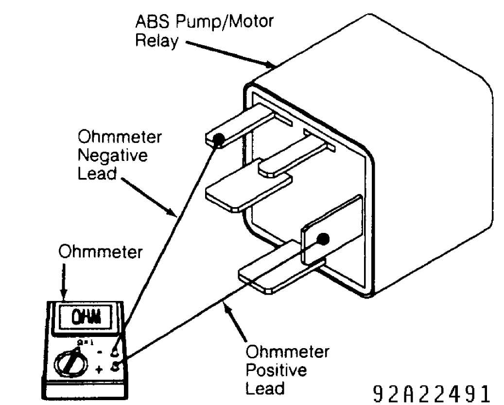
Fig. 17: Checking ABS Pump/Motor Relay Diode
TEST15C
PUMP MOTOR CIRCUIT NOT WORKING PROPERLY
1) Disconnect
ABS pump/motor 4-pin connector at hydraulic
control unit. Ensure
jumper wire is still connected between Red/Dark
Green
wire and Tan/Black wire (Brown/White wire and Red/Dark Blue wire
on
Grand Cherokee and Grand Wagoneer or Tan wire and Red/Brown wire
on
Wrangler) at ABS pump/motor relay socket.
2) With
DRB-II in voltmeter mode, probe Tan/Black wire
(Brown/White
wire on Grand Cherokee and Grand Wagoneer or Tan wire on
Wrangler) at ABS pump/motor 4-pin harness connector. If voltage is more than 9 volts, go to next step. If voltage is less than 9 volts, repair open Tan/Black wire (Brown/White wire on Grand Cherokee and Grand Wagoneer or Tan wire on Wrangler) to 4-pin harness connector. Perform VERIFICATION TEST VER-1A.
3) Turn ignition off. With DRB-II in ohmmeter mode, probe Black/Tan ground wire (Black ground wire on Grand Cherokee and Grand Wagoneer) at ABS pump/motor 4-pin harness connector. If resistance is less than 5 ohms, replace ABS pump/motor assembly. Perform VERIFICATION TEST VER-1A. If resistance is more than 5 ohms, repair open in Black/Tan ground wire (Black ground wire on Grand Cherokee and Grand Wagoneer). Perform VERIFICATION TEST VER-1A.
TEST15D
PUMP MOTOR CIRCUIT NOT WORKING PROPERLY
Using
an external ohmmeter, measure resistance of ABS
pump/motor
speed sensor. See Fig. 18. If sensor
resistance is 10-35
ohms, go to next
step. If resistance is not 10-35 ohms,
replace ABS
pump/motor assembly.
Perform VERIFICATION TEST VER-1A.
Turn
ignition on. With DRB-II in voltmeter mode, probe Tan
wire (Light
Green/Brown wire on Wrangler) at ABS pump/motor 4-pin
harness
connector. If any voltage is present, repair ABS pump/motor
speed
sensor Tan wire (Light Green wire on Wrangler) for a short
to
battery voltage. Perform VERIFICATION TEST VER-1A. If no
voltage is
present, go to next step.
With
DRB-II in voltmeter mode, probe Dark Blue wire (Brown
wire on
Wrangler) at ABS pump/motor 4-pin harness connector. If any
voltage
is present, repair ABS pump/motor speed sensor Dark Blue wire
(Brown wire on Wrangler) for a short to battery voltage. Perform VERIFICATION TEST VER-1A. If no voltage is present, go to next step.
With
DRB-II in ohmmeter mode, probe Tan wire (Light
Green/Brown wire
on Wrangler) at ABS pump/motor 4-pin harness
connector. If
resistance is less than 5 ohms, repair ABS
pump/motor
speed sensor Tan wire (Light
Green/Brown wire on Wrangler) for a short
to
ground. Perform VERIFICATION TEST VER-1A. If resistance is more
than
5 ohms, go to next step.
With
DRB-II in ohmmeter mode, probe Dark Blue wire (Brown
wire on
Wrangler) at ABS pump/motor 4-pin harness connector. If
resistance
is less than 5 ohms, repair ABS pump/motor
speed sensor
Dark Blue wire (Brown wire
on Wrangler) for a short to ground. Perform
VERIFICATION
TEST VER-1A. If resistance is more than 5 ohms,
go to
next step.
6) Using
an external ohmmeter, measure resistance of Tan wire
(Light
Green/Brown wire on Wrangler) between CAB connector terminal
No. 49 and ABS pump/motor 4-pin harness connector. If resistance is less than 5 ohms, go to next step. If resistance is more than 5 ohms, repair open ABS pump/motor speed sensor Tan wire (Light Green/Brown wire on Wrangler). Perform VERIFICATION TEST VER-1A.
7) Using
an external ohmmeter, measure resistance of Dark
Blue
wire (Brown wire on Wrangler) between CAB connector terminal No.
31
and ABS pump/motor 4-pin harness connector. If
resistance is less
than 5 ohms, replace
CAB. Perform VERIFICATION TEST VER-1A. If
resistance is more than
5 ohms, repair open ABS pump/motor
speed
sensor Dark Blue wire (Brown wire on Wrangler).
Perform VERIFICATION
TEST
VER-1A.
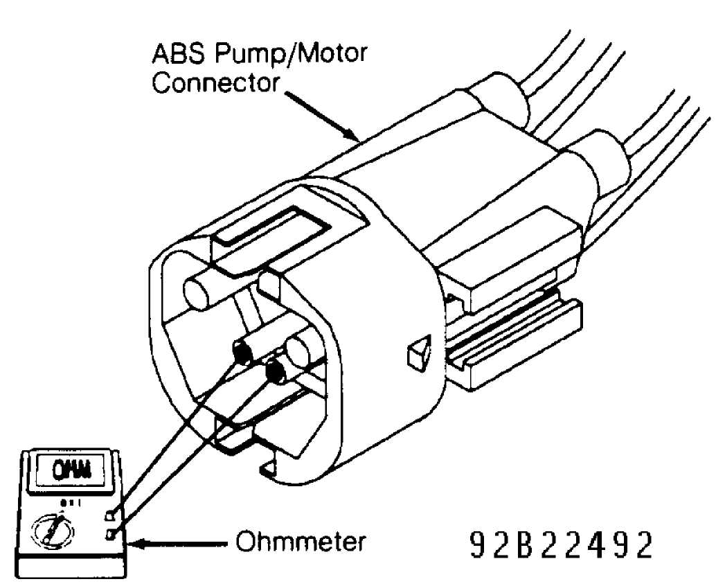
Fig. 18: Checking ABS Pump/Motor Sensor Resistance
TEST16A
RIGHT FRONT INLET VALVE
Disconnect
and inspect Hydraulic Control Unit (HCU) 10-pin
connector. Repair
connector as necessary. Turn ignition on. With DRB-
II in
voltmeter mode, probe White/Tan wire (White/Orange wire on
Grand
Cherokee and Grand Wagoneer or White/Yellow wire on
Wrangler) at HCU
10-pin harness connector. If no voltage is
present, go to next step.
If any voltage is present, repair
White/Tan wire (White/Orange wire on
Grand Cherokee and Grand
Wagoneer or White/Yellow wire on Wrangler)
for a short to battery
power. Perform VERIFICATION TEST VER-1A.
Turn
ignition off. Disconnect and inspect CAB 55-pin
connector. Repair
connector as necessary. With DRB-II in ohmmeter
mode,
probe White/Tan wire (White/Orange wire on Grand Cherokee and
Grand
Wagoneer or White/Yellow wire on Wrangler) at HCU 10-pin
harness
connector. If resistance is
more than 5 ohms, go to next step.
If
resistance is less than 5 ohms,
repair White/Tan wire (White/Orange
wire on Grand Cherokee and
Grand Wagoneer or White/Yellow wire on
Wrangler) for a short to
ground. Perform VERIFICATION TEST VER-1A.
Using an external ohmmeter, measure resistance of
White/Tan wire (White/Orange wire on Grand Cherokee and Grand Wagoneer or White/Yellow wire on Wrangler) between CAB connector terminal No. 38 and HCU 10-pin harness connector. If resistance is less than 5 ohms, go to next step. If resistance is more than 5 ohms, repair open White/Tan wire (White/Orange wire on Grand Cherokee and Grand Wagoneer or White/Yellow wire on Wrangler). Perform VERIFICATION TEST VER-1A.
4) Using an external ohmmeter, measure resistance of right front inlet valve between terminals No. 3 and 5 at HCU pigtail connector. See Fig. 19. If resistance is 5-8 ohms, replace CAB. Perform VERIFICATION TEST VER-1A. If resistance is not 5-8 ohms, replace hydraulic control unit. Perform VERIFICATION TEST VER-1A.
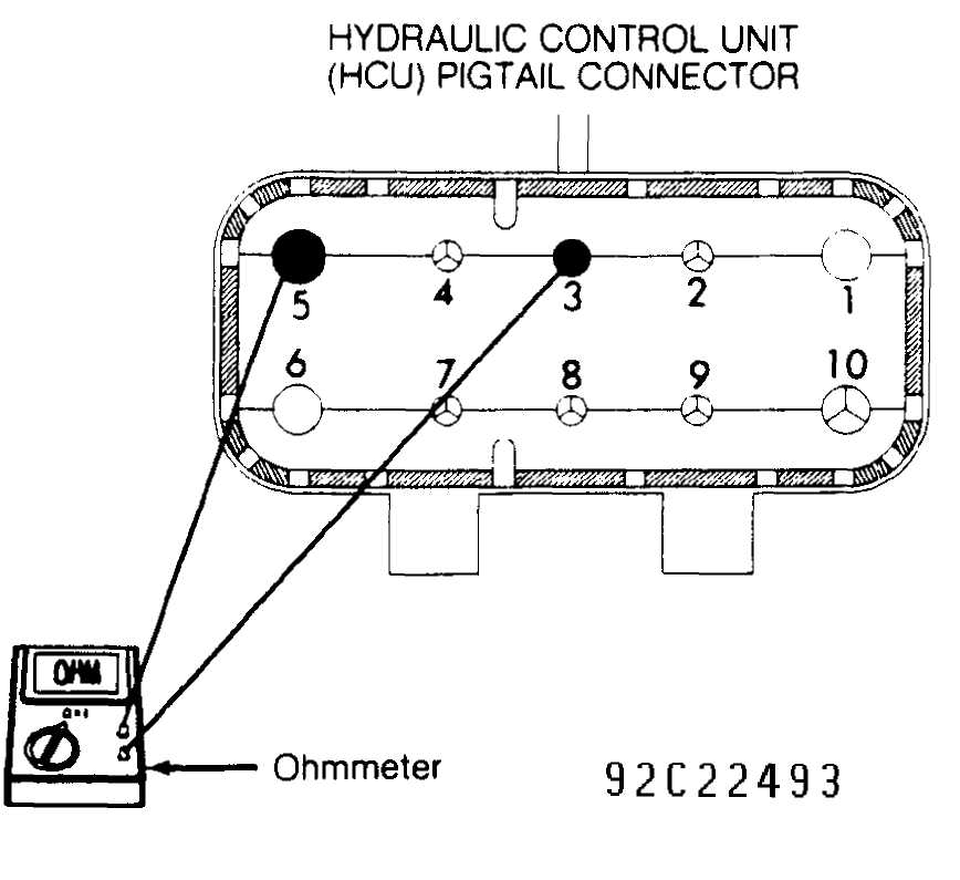
Fig. 19: Checking HCU Right Front Inlet Valve Resistance
TEST17A
RIGHT FRONT OUTLET VALVE
1) Disconnect and inspect Hydraulic Control Unit (HCU) 10-pin
connector. Repair connector as necessary. Turn ignition on. With DRB-II in voltmeter mode, probe Dark Green/White wire at HCU 10-pin harness connector. If no voltage is present, go to next step. If any voltage is present, repair Dark Green/White wire for a short to battery power. Perform VERIFICATION TEST VER-1A.
Turn
ignition off. Disconnect and inspect CAB 55-pin
connector. Repair
connector as necessary. With DRB-II in ohmmeter
mode, probe Dark
Green/White wire at HCU 10-pin harness connector. If
resistance
is more than 5 ohms, go to next step. If
resistance is less
than 5 ohms,
repair Dark Green/White wire for a short to ground.
Perform
VERIFICATION TEST VER-1A.
Using
an external ohmmeter, measure resistance of Dark
Green/White wire
between CAB connector terminal No. 21 and
HCU 10-pin
harness connector. If
resistance is less than 5 ohms, go to next
step.
If resistance is more than 5
ohms, repair open Dark Green/White wire.
Perform
VERIFICATION TEST VER-1A.
Using
an external ohmmeter, measure resistance of right
front outlet
valve between terminals No. 8 and 10
at HCU connector.
See
Fig. 19. If resistance is 3-5 ohms,
replace CAB. Perform
VERIFICATION TEST VER-1A. If resistance is
not 3-5 ohms, replace
hydraulic control
unit. Perform VERIFICATION TEST VER-1A.
TEST18A
RIGHT FRONT SENSOR CIRCUIT FAILURE
1) Using DRB-II, read and record all wheel speed sensor
faults. If RIGHT FRONT SENSOR CIRCUIT FAILURE message is displayed, go to next step. If message is not displayed, perform TEST 19A.
Inspect
right front wheel speed sensor for damage. If
sensor is okay, go
to next step. If sensor is damaged, repair or
replace as
necessary. Perform VERIFICATION TEST VER-1A.
Turn
ignition off. Disconnect and inspect CAB 55-pin
connector.
Repair connector as necessary. Turn ignition on. With DRB-
II
in voltmeter mode, probe White wire at CAB connector terminal
No.
47. If no voltage is present, go to
next step. If any voltage is
present,
repair White wire for a short to battery power. Perform
VERIFICATION
TEST VER-1A.
Turn
ignition off. With DRB-II in ohmmeter mode, probe
White wire at
CAB connector terminal No. 47. If
resistance is more
than 5 ohms,
go to next step. If resistance is less than 5 ohms,
repair
White wire for a short to ground. Perform VERIFICATION TEST
VER-1A.
Using
an external ohmmeter, measure resistance of right
front wheel
speed sensor between White/Dark Blue wire and White wire
at CAB
connector terminals No. 29 and 47.
If resistance is 900-1300
ohms,
replace CAB. Perform VERIFICATION TEST VER-1A. If resistance is
not
900-1300 ohms, go to next step.
Disconnect
right front wheel speed sensor harness
connector. Connector is
located on right rear corner of engine
compartment. Using an
external ohmmeter, measure resistance of right
front
wheel speed sensor at harness connector terminals. If resistance
is
900-1300 ohms, go to next step. If
resistance is not 900-1300 ohms,
replace
sensor. Perform VERIFICATION TEST VER-1A.
Using
an external ohmmeter, measure resistance of White
wire between
CAB connector terminal No. 47 and right
front wheel speed
sensor harness connector. If resistance is less
than 5 ohms, repair
open White/Dark
Blue wire. Perform VERIFICATION TEST VER-1A. If
resistance is
more than 5 ohms, repair open White wire.
Perform
VERIFICATION TEST VER-1A.
TEST19A
RIGHT FRONT SENSOR
Inspect
right front wheel speed sensor for damage. If
sensor is okay, go
to next step. If sensor is damaged, repair or
replace as
necessary. Perform VERIFICATION TEST VER-1A.
Inspect
right front wheel speed sensor tone (pulse) ring
for
damaged teeth or excessive runout. Runout should not exceed
.003"
(.08 mm). Repair
or replace tone ring as necessary. Perform
VERIFICATION TEST VER-1A. If tone ring is okay, go to next step.
Using
a feeler gauge, check right front wheel sensor-to-
tone ring
clearance. If clearance is .036-.050" (.91-1.27 mm),
go to
next step. If clearance is not
.036-.050" (.91-1.27 mm), repair
as
necessary. Perform VERIFICATION TEST
VER-1A.
Inspect
right front wheel speed sensor wiring harness for
damage. If
wiring harness is okay, go to next step. If wiring harness
is
damaged, repair wiring harness as necessary. Perform
VERIFICATION
TEST VER-1A.
Disconnect
right front wheel speed sensor harness
connector. Connector is
located on right rear corner of engine
compartment. Using an
external ohmmeter, measure resistance of right
front
wheel speed sensor at harness connector terminals. If resistance
is
900-1300 ohms, replace CAB. Perform
VERIFICATION TEST VER-1A. If
resistance is not 900-1300
ohms, replace sensor. Perform VERIFICATION
TEST
VER-1A.
NOTE: If excessive axle deflection occurs on extremely bumpy
surfaces or during off road use, it is possible for a wheel speed sensor to set a code.
TEST 20A
RIGHT REAR SENSOR CIRCUIT FAILURE
Using
DRB-II, read and record all wheel speed sensor
faults. If RIGHT
REAR SENSOR CIRCUIT FAILURE message is displayed, go
to next
step. If message is not displayed, perform TEST 21A.
Inspect
right rear wheel speed sensor for damage. If
sensor is okay, go
to next step. If sensor is damaged, repair or
replace as
necessary. Perform VERIFICATION TEST VER-1A.
Turn ignition off. Disconnect and inspect CAB 55-pin
connector. Repair connector as necessary. Turn ignition on. Using DRB-II in voltmeter mode, probe Yellow wire (Yellow/Dark Blue wire on Wrangler) at CAB connector terminal No. 27. If no voltage is present, go to next step. If any voltage is present, perform TEST 20B.
4) Using DRB-II in ohmmeter mode, probe Yellow wire
(Yellow/Dark Blue wire on Wrangler) at CAB connector terminal No. 27. If resistance is more than 5 ohms, go to next step. If resistance is less than 5 ohms, perform TEST 20C.
Using
an external ohmmeter, measure resistance of right
rear
wheel speed sensor between Yellow wire and Yellow/Dark Blue wire
at
CAB connector terminals No. 27 and 45.
If resistance is 900-1300
ohms,
replace CAB. Perform VERIFICATION TEST VER-1A. If resistance is
not
900-1300 ohms, go to next step.
Disconnect
right rear wheel speed sensor. Using an
external ohmmeter,
measure resistance of right rear wheel speed
sensor.
If resistance is 900-1300 ohms, go to next
step. If resistance
is not 900-1300
ohms, replace sensor. Perform VERIFICATION TEST
VER-
1A.
Connect a jumper wire between ground and Yellow/Dark Blue
wire (Yellow wire on Wrangler) at CAB connector terminal No. 45. With DRB-II in ohmmeter mode, measure resistance of Yellow wire (Yellow/Dark Blue wire on Wrangler) at right rear wheel speed sensor harness connector. If resistance is less than 5 ohms, perform TEST 20E. If resistance is more than 5 ohms, perform TEST 20D.
TEST 20B
RIGHT REAR SENSOR CIRCUIT FAILURE
On
Cherokee, repair Yellow wire for a short to battery
power.
Perform VERIFICATION TEST VER-1A. On Wrangler, repair
Yellow/Dark
Blue wire for a short to battery power. Perform
VERIFICATION TEST
VER-1A. On Grand Cherokee and Grand Wagoneer,
disconnect and
inspect Black ABS 8-pin disconnect connector. Connector
is
located behind left kick panel. Repair connector as necessary.
With
DRB-II in voltmeter mode, probe Yellow wire of ABS
disconnect
connector.
If no
voltage is present, repair Yellow wire for a short
to battery
power between right rear wheel speed sensor and ABS
disconnect
connector. Perform VERIFICATION TEST VER-1A. If any voltage
is
present, repair Yellow wire for a short to battery power between
ABS
disconnect connector and CAB 55-pin connector. Perform
VERIFICATION
TEST VER-1A.
TEST 20C
RIGHT REAR SENSOR CIRCUIT FAILURE
On
Cherokee, repair Yellow wire for a short to ground.
Perform
VERIFICATION TEST VER-1A. On Wrangler, repair Yellow/Dark Blue
wire
for a short to ground. Perform VERIFICATION TEST VER-1A. On
Grand
Cherokee and Grand Wagoneer, disconnect and inspect Black
ABS 8-pin
disconnect connector. Connector is located behind left
side kick
panel. Repair connector as necessary. With DRB-II in
ohmmeter mode,
probe Yellow wire of ABS disconnect connector.
If
resistance is less than 5 ohms, repair
Yellow wire for
a short to ground
between right rear wheel speed sensor and ABS
disconnect
connector. Perform VERIFICATION TEST VER-1A. If resistance
is
more than 5 ohms, repair Yellow wire for a
short to ground between
ABS disconnect
connector and CAB 55-pin connector. Perform
VERIFICATION
TEST VER-1A.
TEST 20D
RIGHT REAR SENSOR CIRCUIT FAILURE
On
Cherokee, repair open Yellow/Dark Blue wire to right
rear wheel
speed sensor. Perform VERIFICATION TEST VER-1A. On
Wrangler,
repair open Yellow wire to right rear wheel speed sensor.
Perform
VERIFICATION TEST VER-1A. On Grand Cherokee and Grand
Wagoneer,
disconnect and inspect Black ABS 8-pin disconnect
connector.
Connector is located behind left kick panel. Repair
connector as
necessary. With DRB-II in ohmmeter mode, probe
Yellow/Dark Blue wire
of ABS disconnect connector.
If
resistance is less than 5 ohms, repair
open Yellow/Dark
Blue wire between
right rear wheel speed sensor and ABS disconnect
connector.
Perform VERIFICATION TEST VER-1A. If resistance is more
than 5
ohms, repair open Yellow/Dark Blue wire between
ABS disconnect
connector and CAB 55-pin connector. Perform
VERIFICATION TEST VER-1A.
TEST 20E
RIGHT REAR SENSOR CIRCUIT FAILURE
On
Wrangler, repair open Yellow/Dark Blue wire to right
rear wheel
speed sensor. Perform VERIFICATION TEST VER-1A. On all
others,
disconnect and inspect Black ABS 8-pin disconnect connector.
On
Cherokee, connector is located on transmission hump near
firewall.
On Grand Cherokee and Grand
Wagoneer, connector is located behind left
side
kick panel. Repair connector as necessary. Connect a jumper
wire
between ground and Yellow wire at CAB connector terminal No.
27. With
DRB-II in ohmmeter mode, probe
Yellow wire of ABS disconnect
connector.
If
resistance is less than 5 ohms, repair
open Yellow wire
between right rear
wheel speed sensor and ABS disconnect connector.
Perform
VERIFICATION TEST VER-1A. If resistance is more than 5
ohms,
repair open Yellow wire between ABS
disconnect connector and CAB 55-
pin connector. Perform
VERIFICATION TEST VER-1A.
TEST 21A
RIGHT REAR SENSOR
Inspect
right rear wheel speed sensor for damage. If
sensor is okay, go
to next step. If sensor is damaged, repair or
replace as
necessary. Perform VERIFICATION TEST VER-1A.
Inspect
right rear wheel speed sensor tone (pulse) ring
for
damaged teeth and excessive runout. Runout should not exceed
.003"
(.08 mm). Repair
or replace tone ring as necessary. Perform
VERIFICATION TEST VER-1A. If tone ring is okay, go to next step.
Using
a feeler gauge, check right rear wheel sensor-to-
tone
ring clearance. If clearance is .036-.050" (.91-1.27
mm), go to
next
step. If clearance is not .036-.050" (.91-1.27 mm),
repair as
necessary. Perform
VERIFICATION TEST VER-1A.
Inspect
right rear wheel speed sensor wiring harness for
damage. If
wiring harness is okay, go to next step. If wiring harness
is
damaged, repair wiring harness as necessary. Perform
VERIFICATION
TEST VER-1A.
Disconnect
right rear wheel speed sensor. Using an
external ohmmeter,
measure resistance of right rear wheel speed
sensor. If
resistance is 900-1300 ohms, replace CAB.
Perform
VERIFICATION TEST VER-1A. If
resistance is not 900-1300 ohms,
replace
sensor. Perform VERIFICATION TEST VER-1A.
NOTE: If excessive axle deflection occurs on extremely bumpy
surfaces or during off road use, it is possible for a wheel speed sensor to set a code.
TEST 22A
ABS WARNING LIGHT ILLUMINATION PROBLEM
1) Using DRB-II, read ABS fault codes. If any fault codes are present, perform TEST 1A. Turn ignition off. Remove ABS main relay from PDC, and inspect connector. Repair connector as necessary. Turn ignition on. If ABS warning light comes on, go to next step. If warning light does not come on, perform VERIFICATION TEST VER-1C.
NOTE: A main relay/power circuit failure fault will set with ABS
main relay removed.
Turn
ignition off. With DRB-II in ohmmeter mode, probe
Black/Tan
ground wire (Black ground wire on Grand Cherokee and Grand
Wagoneer)
at ABS main relay socket. If resistance is less than 5
ohms,
go to next
step. If resistance is more than 5 ohms,
repair open
Black/Tan ground wire (Black ground wire on Grand
Cherokee and Grand
Wagoneer). Perform
VERIFICATION TEST VER-1A.
Ensure
ignition off. Disconnect and inspect CAB 55-pin
connector. Repair
connector as necessary. With DRB-II in voltmeter
mode, probe
Gray/Yellow wire (Gray/Pink wire on Grand Cherokee and
Grand
Wagoneer) at ABS main relay socket. If no voltage is present, go
to
next step. If any voltage is present, replace ABS main
relay.
Perform VERIFICATION TEST VER-1A.
Remove
ABS diode. Diode is taped to wiring harness, near
CAB (near ABS
8-pin disconnect connector on Grand Cherokee and Grand
Wagoneer).
Connect a jumper wire between Gray/Yellow wire
(Gray/Pink
wire on Grand Cherokee and Grand Wagoneer) and
Black/Tan wire (Black
wire on Grand
Cherokee and Grand Wagoneer) at ABS main relay socket
terminals
"B" and "E".
Using
DRB-II in ohmmeter mode, probe Gray/Yellow wire at
ABS diode
connector. If resistance is less than 5 ohms,
go to next
step. If resistance is more
than 5 ohms, repair open Gray/Yellow
wire
between relay splice and diode.
Perform VERIFICATION TEST VER-1A.
Remove
jumper wire used in step 4). Turn ignition
on. If
ABS warning light does not come
on, go to next step. If ABS warning
light
comes on, repair Violet wire (Violet/White wire on Grand
Cherokee
and Grand Wagoneer or Light Green/Orange on Wrangler) for a
short
circuit to ground between CAB connector terminal No. 52 and
ABS
diode.
Turn
ignition off. Connect a jumper wire between ground
and
Violet wire (Violet/White wire on Grand Cherokee and Grand
Wagoneer
or Light Green/Orange wire on Wrangler) at CAB connector
terminal
No. 52. Using DRB-II in ohmmeter mode,
probe Violet wire
(Violet/White wire on Grand Cherokee and Grand Wagoneer or Light Green/Orange wire on Wrangler) at ABS diode connector. If resistance is less than 5 ohms, replace ABS diode. Perform VERIFICATION TEST VER-1A. If resistance is more than 5 ohms, repair open Violet wire
(Violet/White wire on Grand Cherokee and Grand Wagoneer or Light Green/Orange wire on Wrangler) between ABS warning light and diode. Perform VERIFICATION TEST VER-1A.
TEST 23A
NO RESPONSE MESSAGE
On
Cherokee, remove and inspect fuse No. 7. If
fuse is
blown, check for possible short to ground in Light
Green/Yellow wire
between ignition switch and terminal No. 53
of CAB connector. If fuse
is
okay, go to next step. On Grand Cherokee and Grand Wagoneer,
remove
and inspect fuse No. 15. If fuse
is blown, check for possible short to
ground in Light
Green/Yellow wire between ignition switch and terminal
No.
53 of CAB connector. If fuse is okay, go
to next step. On
Wrangler, remove and inspect fuse No. 13.
If fuse is blown, check for
possible short to
ground in Yellow/Dark Green wire between ignition
switch and
terminal No. 53 of CAB connector. If fuse
is okay, go to
next step.
On
all models, turn ignition off. Disconnect and inspect
CAB
55-pin connector. Repair connector as necessary. Turn ignition
on.
With DRB-II in voltmeter mode,
probe terminal No. 53 (Light
Green/Yellow
wire on Cherokee and Grand Cherokee and Grand Wagoneer
or
Yellow/Dark Green wire on Wrangler)
of CAB connector.
If
voltage is less than 9 volts, repair open
in Light
Green/Yellow wire (Cherokee and Grand Cherokee and Grand
Wagoneer) or
Yellow/Dark Green wire (Wrangler). Perform
VERIFICATION TEST VER-1A.
If voltage is
more than 9 volts, turn ignition off. With
DRB-II in
ohmmeter mode, probe terminal
No. 1 (Black wire) of CAB connector.
If
resistance is more than 5
ohms, repair open Black wire.
Perform
VERIFICATION TEST VER-1A.
If
resistance is less than 5 ohms, probe
terminal No. 19
(Black wire) of CAB
connector. If resistance is more than 5 ohms,
repair
open Black wire. Perform VERIFICATION TEST VER-1A. If
resistance
is less than 5 ohms, check resistance of
Violet/Brown wire
(White/Violet wire on Wrangler) between
terminals No. 4 of CCD bus
diagnostic connector and No. 23 of CAB connector using an external ohmmeter.
If
resistance is more than 5 ohms, repair
open in
Violet/Brown wire (White/Violet
wire on Wrangler). Perform
VERIFICATION
TEST VER-1A. If resistance is less than 5 ohms,
using an
external ohmmeter, check
resistance of White/Black wire on Cherokee,
White/Gray wire on
Grand Cherokee and Grand Wagoneer or Orange wire on
Wrangler
between terminal No. 3 of CCD bus
diagnostic connector and
No. 42
of CAB connector.
If resistance is more than 54 ohms, repair open in
White/Black wire (Cherokee), White/Gray wire (Grand Cherokee and Grand Wagoneer) or Orange wire (Wrangler). Perform VERIFICATION TEST VER-1A. If resistance is less than 5 ohms, turn ignition off. Reconnect CAB 55-pin connector. Using DRB-II, try to access ABS TEVES diagnostics. If DRB-II does not display NO RESPONSE, system is functioning properly. If DRB-II displays NO RESPONSE, replace CAB. Perform VERIFICATION TEST VER-1A.
VERIFICATION TEST VER-1A
SYSTEM VERIFICATION TEST
Disconnect
all previously connected jumper wires.
Reconnect
all previously disconnected connectors. Reinstall all
previously
removed relays. Replace any blown fuses. Using DRB-II,
erase
fault messages. Cycle ignition off and then on. Using
DRB-II,
monitor read faults display for
3 minutes. If DRB-II displays any
faults,
perform TEST 1A.
If
DRB-II does not display any faults, using DRB-II, read
brakelight
switch input. Depress brake pedal. If DRB-II does not
display
PRESSED, perform VERIFICATION TEST VER-1B. If DRB-II
displays
PRESSED, using DRB-II, read
"G" SWITCH input. If DRB-II does not
display
"G" SWITCH #1 CLOSED, "G"
SWITCH #2 CLOSED, perform TEST 3A.
If
DRB-II displays No. 1 and 2 "G"
switch CLOSED, with
DRB-II in ABS TEVES
diagnostic mode, check ANTI-LOCK warning light. If
warning
light is off, perform, VERIFICATION TEST VER-1C. If warning
light
is flashing, depress brake pedal. Using DRB-II, actuate left
front
outlet valve.
If brake pedal "drop" was not felt when valve was
actuated, replace hydraulic control unit. Perform VERIFICATION TEST VER-1A. If brake pedal "drop" was felt when valve was actuated, release brake pedal. Depress brake pedal. Using DRB-II, actuate right front outlet valve.
5) If brake pedal "drop" was not felt when valve was
actuated, replace hydraulic control unit. Perform VERIFICATION TEST VER-1A. If brake pedal "drop" was felt when valve was actuated, release brake pedal. Depress brake pedal. Using DRB-II, actuate rear outlet valve.
6) If
brake pedal "drop" was not felt when valve was
actuated,
replace hydraulic control unit. Perform VERIFICATION TEST
VER-1A. If brake pedal "drop" was felt when valve was actuated, road test vehicle for a minimum of 5 minutes and perform several anti-lock braking stops.
7) Using DRB-II, read fault messages. If DRB-II displays any faults, perform TEST 1A. If DRB-II displays no faults, system is operating properly.
VERIFICATION TEST VER-1B
BRAKELIGHT SWITCH SENSOR CIRCUIT
Check
brakelight operation. If brakelights are not
operating properly,
repair as necessary. Perform VERIFICATION TEST
VER-1A. If
brakelights are operating properly, turn ignition off.
Disconnect
and inspect CAB 55-pin connector. Repair connector as
necessary.
Depress
brake pedal. With DRB-II in voltmeter mode, probe
terminal No. 32
(White/Tan wire) of CAB connector. If voltage is
less
than 9 volts,
repair open White/Tan wire. Perform VERIFICATION TEST
VER-1A.
If voltage is more than 9 volts, replace
CAB. Perform
VERIFICATION TEST VER-1A.
VERIFICATION TEST VER-1 C
ANTI-LOCK WARNING LIGHT CIRCUIT
Set
parking brake. Turn ignition on. If Red BRAKE warning
light is
off, repair fused ignition feed circuit to warning lights.
Perform
VERIFICATION TEST VER-1A. If Red BRAKE warning light is on,
turn
ignition off. Disconnect and inspect CAB 55-pin connector.
Repair
connector as necessary.
Turn
ignition on. Connect a jumper wire between terminal
No.
52 (Violet wire on Cherokee or
Violet/White wire on Grand Cherokee
and Grand Wagoneer or Light
Green/Orange wire on Wrangler) and ground.
Check
ANTI-LOCK warning light. If ANTI-LOCK warning light is on,
replace
CAB. Perform VERIFICATION TEST VER-1A.
If
ANTI-LOCK warning light is off, inspect ANTI-LOCK
warning light
bulb. Replace bulb as necessary. Perform VERIFICATION
TEST
VER-1A. If bulb is okay, repair open Violet wire (Cherokee)
or
Violet/White wire (Grand Cherokee
and Grand Wagoneer) or Light
Green/Orange wire (Wrangler).
Perform VERIFICATION TEST VER-1A.
TORQUE SPECIFICATIONS
TORQUE SPECIFICATIONS TABLE
Application Ft. Lbs. (N.m)
Combination Valve Brakeline Fittings 13-18 (18-24)
Front Speed Sensor Bolt 11 (15)
HCU Brakeline Fittings 10-12 (14-16)
Master Cylinder Brakeline Fittings 11-13 (15-18)
Rear Speed Sensor Bolt 11 (15)
Wheel Lug Nuts 88 (119)
INCH Lbs. (N.m)
CAB Mounting Bolts 75-115 (9-13)
"G" Switch Bolt 17-32 (2-4)
HCU Bracket Mounting Bolts 92-112 (10-13)
WIRING DIAGRAMS
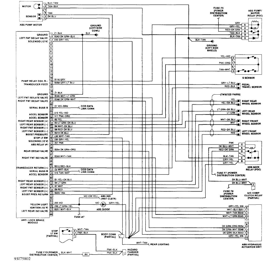
Fig. 20: ABS Wiring Diagram (Cherokee)
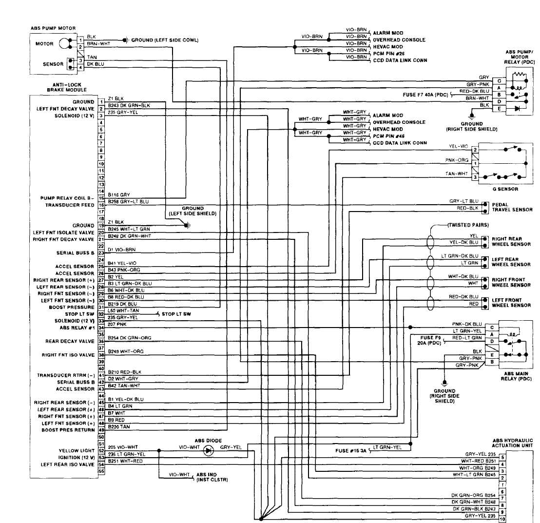 93.T75803
Fig. 21: ABS Wiring Diagram (Grand Cherokee
& Grand Wagoneer)
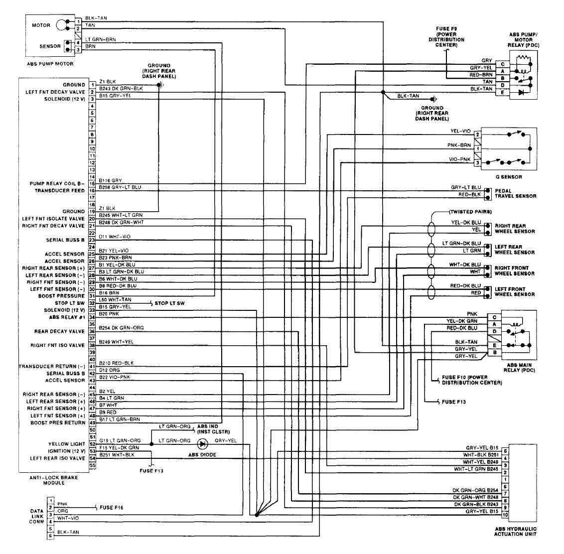
93A75804 Fig. 22: ABS Wiring Diagram (Wrangler)