ENGINE COOLING FAN
1988 Jeep Cherokee
1987-88 ENGINE COOLING
Thermostatically Controlled Electric Fans
Cherokee, Comanche, Wagoneer
DESCRIPTION & OPERATION
On Cherokee, Comanche and Wagoneer models with a 4.0L engine, A/C and/or heavy duty cooling system, an auxiliary electric fan is used. The auxiliary fan is controlled by a relay mounted on the left inner fender panel. A radiator temperature switch attached to the radiator outlet tank above the lower radiator hose senses engine coolant temperature.
When coolant temperature is more than 190 (0)F (88(0)C), the radiator coolant temperature switch closes allowing current from the ignition switch to flow through the fan relay to ground activating the relay. When relay is activated, battery voltage is supplied to the fan causing it to operate. When coolant temperature is below 190 (0)F (88(0)C), the radiator coolant temperature switch opens preventing the relay from being grounded and electric cooling fan from being energized.
When the A/C (if equipped) is turned on, the Electronic
Control Unit (ECU) grounds the A/C relay coil allowing current to flow through it. This activates the A/C relay which then supplies current to the A/C clutch, fan diode assembly and cooling fan relay. The cooling fan relay is activated and the fan operates. Whenever the A/C is used, regardless of engine coolant temperature, the auxiliary electric cooling fan operates.
TESTING
NOTE: For following tests, refer to fan relay connector terminal identification and fan controls identification. See Figs. 1 and 2 .
With Air Conditioning
If electric cooling fan does not work all the time, go to
step 3). If electric cooling fan is inoperative when A/C compressor
operates, start engine and turn A/C on. Disconnect fan relay
connector. Fan relay is located on left inner fender panel.
Using a voltmeter, check for voltage at fan relay
connector terminal No. 2. If voltmeter does not read battery voltage, replace fan diode assembly.
Disconnect fan relay connector. Fan relay is located on
left inner fender panel. Using a jumper wire with an in-line 25-amp
fuse, supply battery voltage to fan relay connector terminal No. 4.
If fan operates, motor is okay. Go to next step. If fan
motor does not operate, check continuity between fan relay connector
terminal No. 4 and body ground connections. If continuity exists,
replace fan motor. If continuity does not exist, repair open and
retest.
Disconnect fan relay connector. Turn ignition switch to
the "RUN" position. Check continuity between fan relay connector
terminal No. 5 and body ground connections. If continuity does not
exist, repair open circuit. If continuity exists, go to next step.
Using a jumper wire with an in-line 25-amp fuse, jump
across fan relay connector terminals No. 1 and No. 4. If fan motor
operates, go to next step. If fan motor does not operate, repair fan
relay fuse link.
Check for battery voltage at fan relay connector terminal
No. 2. Connect a jumper wire across radiator temperature switch
connector. Radiator temperature switch is located on radiator outlet
tank, above lower radiator hose. If fan does not operate, replace
radiator temperature switch. If fan operates, go to next step.
Check for battery voltage at fan relay connector terminal
No. 2. If battery voltage is not present, replace fan diode assembly.
Without Air Conditioning
Disconnect fan relay. Fan relay is mounted on left inner
fender panel. Using a jumper wire with an in-line 25-amp fuse, supply
battery voltage to fan relay connector terminal No. 4.
If fan operates, motor is okay. Go to next step. If fan
motor does not operate, check continuity between fan relay connector
terminal No. 4 and body ground connections.
If continuity exists, replace fan motor. If continuity does not exist, repair open and retest.
With fan relay connector disconnected, turn ignition
switch to the "RUN" position. Check continuity between fan relay
connector terminal No. 5 and body ground connections. If continuity
does not exist, repair open. If continuity exists, go to next step.
Using a jumper wire with a 25-amp in-line fuse, jump
across fan relay connector terminals No. 1 and No. 4. If fan motor
operates, leave jumper wire connected and proceed to next step. If fan
motor does not operate, repair fan relay fuse link.
Check for battery voltage at cooling fan relay connector
terminal No. 2. Connect a jumper wire across radiator coolant
temperature switch connector. Radiator coolant temperature switch is
located on radiator outlet tank above lower radiator hose. If fan does
not operate, replace radiator coolant temperature switch.
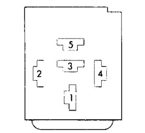
Fig. 1: Fan Relay Connector Terminal Identification Courtesy of Chrysler Motors.
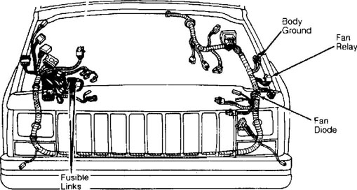
Fig. 2: Fan Controls Identification Courtesy of Chrysler Motors.
REMOVAL & INSTALLATION
AUXILIARY ELECTRIC COOLING FAN
Removal
Auxiliary fan is attached to radiator upper crossmember
behind radiator.
Remove fan retaining screws from radiator upper
crossmember. Disconnect electric fan connector. Lift fan straight up out of vehicle.
Disassembly
Components of auxiliary electric cooling fan can be replaced. However, components cannot be repaired. If an auxiliary cooling fan component needs repair it must be replaced with the recommended replacement part only. The auxiliary fan consists of a fan module, fan module retaining clip, fan shroud, and fan motor.
1) Place assembly on bench with fan blades facing up. Position an awl between the fan retainer and motor shaft. Pry the retainer off the motor shaft. Slide fan up off of motor.
Unwind fan motor electrical connector from retaining
clips of fan shroud.
Remove fan motor mounting screws. Remove fan.
Assembly
1) Attach fan motor to fan shroud with mounting screws. Wind electrical connector into retaining clips of fan shroud.
The bushing at fan module center has a small groove on the bottom side of it that fits over the alignment dowel on the fan motor shaft. The keyway pin of the alignment dowel fits into the groove in fan motor shaft. A small amount of silicone sealant placed in the groove of the fan motor shaft holds the alignment dowel in place.
2) Place fan module over motor shaft, align groove in fan module with dowel on motor shaft. Start fan module retainer onto the fan motor shaft with open end of the retainer facing the groove in the shaft. When retainer is completely installed the open end will be on side opposite the groove. Use needle nose pliers to finish installing retainer.
Installation
Align lower retaining tabs of fan shroud with slots in
bracket at bottom of radiator and push fan down into position. Tighten mounting screws to 36 inch lbs. (4.07 N.m) . Connect auxiliary cooling fan electrical connector.
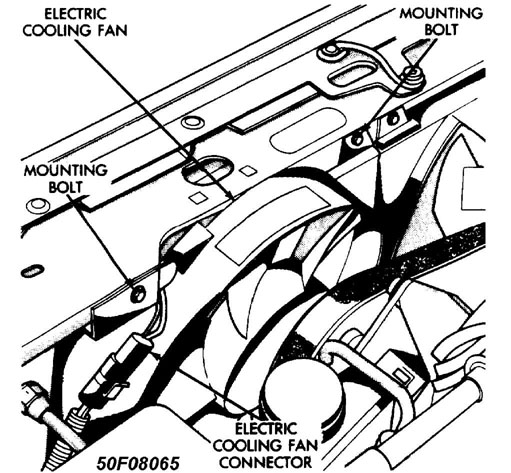
Fig. 3: Auxiliary Fan Removal & Installation
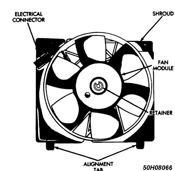
Fig. 4: Auxiliary Fan
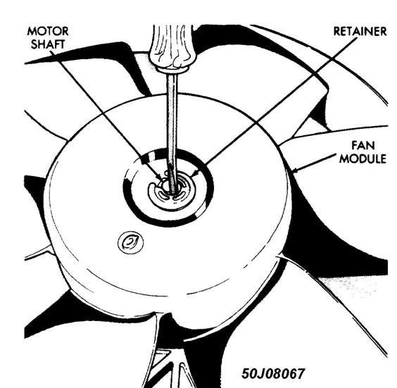
Fig. 5: Fan Module Removal
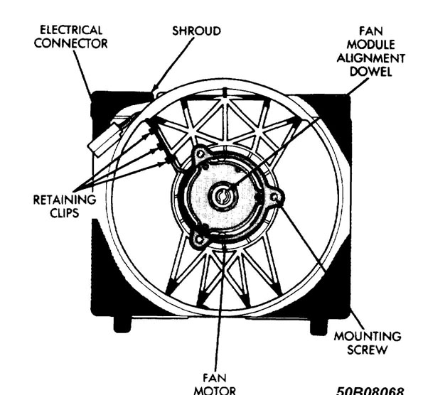
Fig. 6: Fan Motor Removal & Installation
ALIGNMENT GROOVE
 Fig. 7: Alignment Groove in Fan Module Bushing
 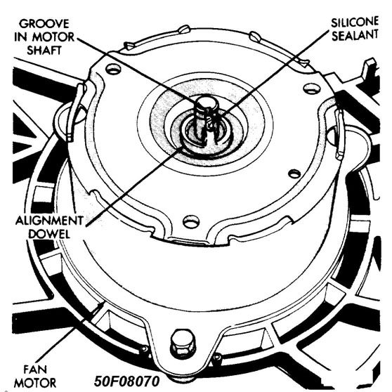 Fig.
Fig.
Alignment Dowel (Fan Module to Motor)
WIRING DIAGRAMS
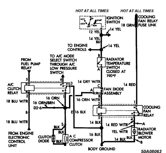
Fig. 9: Wiring Diagrams (With A/C)
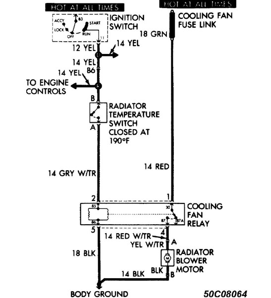
Fig. 10: Wiring Diagrams (Without A/C)
FAN MODULE