DRIVE SHAFT ALIGNMENT
1988 Jeep Cherokee
1988 Drive Shafts Alignment
DESCRIPTION
Drive shafts are balanced, one-piece, tubular shafts with universal joints at each end. Number used in vehicle varies: one shaft, 2 shafts with a center bearing, or 3 shafts. Three shafts are used in many 4WD applications. Location of slip joints varies with model and manufacturer. See Fig. 1.
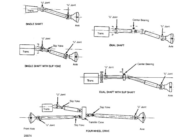
Fig. 1: View of 5 Commonly Used Drive Shaft Combinations Many 4WD models use 3 drive shafts.
INSPECTION
Vibration can come from many sources. Before overhauling driveline, check other sources of possible vibration as follows:
Tires and wheels - Check tire inflation and wheel balance.
Check for foreign objects in tread, damaged tread, mismatched
tread patterns or incorrect tire size.
Center Bearing - Tighten drive shaft center bearing
mounting bolts. If bearing insulator is deteriorated or
oil-soaked, replace it.
Engine & Transmission Mountings - Tighten mounting bolts.
If mountings are deteriorated, replace them.
Drive Shaft - Check drive shaft for damage or dents that
could affect balance. Check for undercoating adhering to
shafts. If present, clean shafts thoroughly.
Universal Joints - Check for foreign material stuck in
joints. Check for loose bolts and worn bearings.
ADJUSTMENTS
DRIVE SHAFT PHASING
One-Piece Shafts
Check that flanges on either end of drive shaft are in same plane. Often there are arrows on slip joint and drive shaft to aid in alignment. See Fig. 2. If flanges are not in same plane, disassemble universal joint and align.
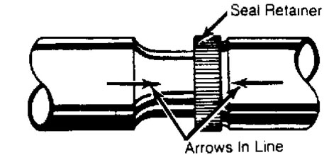
Fig. 2: Slip Joint Alignment Arrows Align arrows for proper shaft phasing.
2-Piece Shafts
1) All General Motors models with 32 splines use keys on spline and slip joint, which can only mate in correct position. On most models with 2-piece shafts, proper phasing is accomplished by keys on spline and slip joint.
2) On models with 2-piece shafts, rotate transmission yoke
until trunnion is in horizontal plane. Install front drive shaft with
"U" joint trunnion in vertical plane. Connect bearing support to
crossmember.
3) Ensure that front face of bearing support is perpendicular
(90 degrees) to centerline of drive shaft. Install rear drive shaft
with "U" joint trunnion of slip joint in vertical plane.
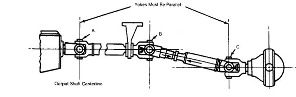
4) Set differential pinion yoke trunnion in vertical plane.
Connect rear drive shaft to pinion yoke. If 2-piece shaft is correctly
installed, centerline of trunnions at each end of individual shafts
will be parallel. See Fig. 3.
28880
Fig. 3: Phase Alignment Of 2-Piece Drive Shafts Trunnion yoke ears on each shaft must be parallel.
DRIVE SHAFT BALANCE TEST
1) Drive shaft imbalance may often be cured by disconnecting
shaft and rotating it 180 degrees in relation to other components.
Test by raising rear wheels off ground, and turning shaft with engine.
NOTE: DO NOT run engine without ram airflow across radiator for
prolonged periods, as overheating of engine or transmission may occur.
On most models, balance testing may be done by marking
shaft in 4 positions, 90 degrees apart. Place marks approximately 6"
forward of weld, at rear end of shaft. Number marks one through 4.
Place screw-type hose clamp so clamp head is in number one
position, and rotate shaft with engine. If there is little or no
change, move clamp head to No. 2 position, and repeat test.
Continue procedure until vibration is at lowest level. If
no difference is noted with clamp head moved to all 4 positions,
vibrations may not be drive shaft imbalance.
If vibration is lessened but not completely gone, place 2
clamps at that point, and run test again. Combined weight of clamps in
one position may increase vibration. If so, rotate clamps 1/2" apart,
above and below best position, and repeat test.
Continue to rotate clamps as necessary, until vibration is
at lowest point. If vibration level is still unacceptable, leave rear
clamp(s) in position and repeat procedure at front end of drive shaft.
If vibration can be eliminated or reduced to acceptable levels using
this test procedure, send drive shaft out to be balanced.
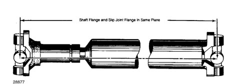
Fig. 4: Drive Shaft Phase Alignment
Align drive shaft and slip joint trunnions in same plane.
FLANGE ALIGNMENT & RUNOUT
1) All flanges must be perpendicular in both vertical and horizontal planes to engine crankshaft. Only exception is "broken back" type driveline, which has flanges that are not perpendicular in vertical plane. See Fig. 5.
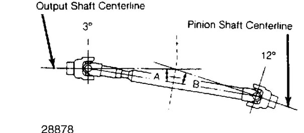
Fig. 5: Typical "Broken Back" Type Drive Shaft Alignment Angle "A" equals angle "B".
With nonparallel or "broken back" type installation,
working angles of universal joints of given drive shaft are equal.
Angle "A" = angle "B" .
This is calculated as follows: angle of output shaft
centerline is subtracted from angle of drive shaft. Difference should
equal angle of drive shaft subtracted from pinion shaft angle.
Parallel type joints maintain constant velocity between
output shaft and pinion shaft. Vibration is minimized and component
life maximized when universal joints are parallel.
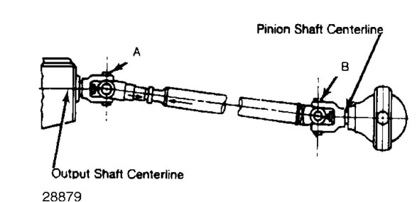
Fig. 6: Aligning One-Piece Drive Shaft Yokes must be parallel.
Using dial indicator, measure runout of transmission
flange, center bearing flange and pinion flange. If runout exceeds .
003-.005" (.08-.13 mm), replace flange.
If dial indicator cannot be used, push rod with snug fit
through flange bearing bore. See if it aligns with opposite flange
bore. If not, replace flange.
Rotate transmission flange until it is vertical, measuring
from side. Check center bearing and pinion flanges. They cannot be
more than one degree off vertical. See DRIVE SHAFT PHASING in this
article.
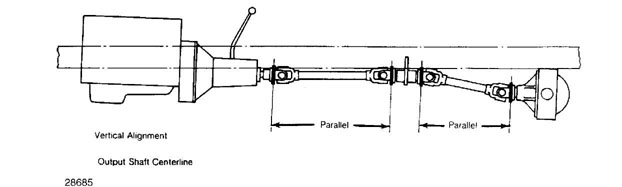
Fig. 7: Vertical Alignment of Drive Shaft Flanges in pairs should be parallel.
8) Rotate transmission flange until it is vertical, measured from side. Measure angle from end and record it. Check all other flanges for same angle. They must be within 1/2 degree of each other. Adjust as required.
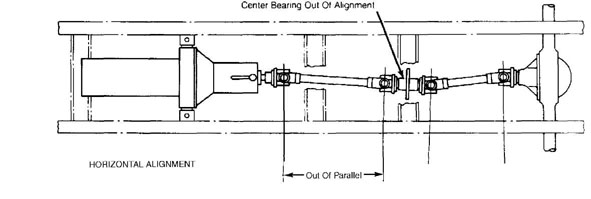
9) If difficulty is encountered when making these adjustments, horizontal alignment should be checked. Even though vertical alignment is correct, horizontal alignment can be badly out of adjustment. This is often found after major component replacement or repair of serious accident damage. See Fig. 8.
28881
Fig. 8: Horizontal Alignment of Drive Shaft Plane of trunnions should be parallel.
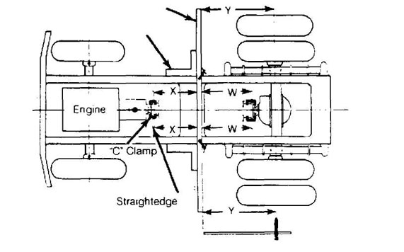
10) To make horizontal alignment checks, set straightedges up. See Fig. 9. Set transmission output flange horizontal and clamp straightedge to flange in a horizontal plane. Repeat procedure with drive pinion flange. Ensure that flanges are horizontal by checking angle of straightedge with spirit level.
Straightedge Framing Square
28882
Fig. 9: Checking Horizontal Alignment
Measure at 6 points shown using straightedges and framing squares.
11) Using straightedge that is 12" longer than width of rear wheel track at 90 degrees, clamp to frame side rails. Use large
framing squares to align straightedge with side rails.
Measure distance "X" at each side. If both measurements
are not within 1/16" (1.6 mm) of each other, transmission flange is
horizontally misaligned.
Measure distance "Y" (edge of straightedge to axle shaft
centerline) at each side. If 2 dimensions are not within 1/8" (3.2 mm)
of each other, axle housing is misaligned.
Measure distance "W" at each side. If both measurements
are not within 1/16" (1.6 mm) of each other, pinion flange is
horizontally misaligned.
