SUSPENSION - FRONT
1988 Jeep Cherokee
1988 FRONT SUSPENSION Jeep Coil & Leaf Spring
Cherokee, Comanche, Grand Wagoneer, Wagoneer, Wrangler
DESCRIPTION
Cherokee, Comanche and Wagoneer 2WD and 4WD front
suspensions consist of solid axle (tubular axle on 2WD), 4 control arms, 2 coil springs and track bar. Track bar is used to minimize front axle side-to-side movement. Stabilizer bar and shock absorbers control suspension spring movement.
Grand Wagoneer and Wrangler models use leaf spring front suspension with shock absorbers and stabilizer bar. Wrangler also uses a track bar to maintain lateral position of front and rear axles.
ADJUSTMENTS
WHEEL ALIGNMENT
See WHEEL ALIGNMENT SPECIFICATIONS & PROCEDURES in WHEEL ALIGNMENT section.
WHEEL BEARING
NOTE: Bearings should be cleaned, inspected, replaced (if necessary) and lubricated before adjustment.
CAUTION: Never preload tapered roller bearings or damage to roller ends will result. Bearings are designed to have a slightly loose feel when properly adjusted.
2WD Models
Raise and
support vehicle. Remove wheel and tire
assembly. Remove hub dust
cap, cotter pin and nut retainer. Ensure
bearings are thoroughly
packed with lithium grease.
Rotate
hub and rotor assembly by hand, and tighten
retainer nut to 17-25
ft. lbs. (23-34 N.m) to
seat bearings.
Loosen
retainer nut 1/2 turn while rotating hub.
Then
retighten nut to 19 INCH
lbs. (2 N.m). Install
nut retainer and new
cotter pin. Clean hub dust cap and coat
inside with clean grease.
Reverse removal procedure for remaining
components.
4WD Models (Grand Wagoneer)
On
models equipped with locking hubs, remove locking
hubs.
See appropriate LOCKING HUBS article. On models without
locking
hubs, remove hub dust cap and
drive gear snap ring. See Fig. 1.
Remove
drive gear, pressure spring and spring cup. On
all
models, remove outer lock nut and lock washer. Tighten inner
lock
nut to 50 ft. lbs. (68 N.m)
while rotating wheel.
Back
off inner lock nut 45-65 degrees while
rotating
wheel. Install washer and
outer lock nut. Tighten outer lock nut to
50 ft.
lbs. (68 N.m). Reverse
removal procedure to complete
installation.
REMOVAL & INSTALLATION
WHEEL BEARINGS
Removal (2WD Models)
Raise and
support vehicle. Remove wheel assembly. Remove
brake caliper.
Suspend caliper with wire. DO NOT allow caliper to
hang on brake
hose.
Remove
hub dust cap, cotter pin, nut retainer, retainer
nut, washer and
outer wheel bearing. See Fig. 1. Remove
hub and rotor
assembly. Pry grease seal from hub. Remove inner
wheel bearing.
Inspection
Clean bearings and hub in solvent and dry with compressed air. Inspect bearings and races for wear.
Installation
To install, reverse removal procedure. Adjust wheel bearing. See WHEEL BEARING under ADJUSTMENTS in this article.
Removal (4WD Grand Wagoneer)
Raise and
support vehicle. Remove wheel assembly. Remove
brake caliper.
Suspend caliper with wire. DO NOT allow caliper to
hang on brake
hose. Remove rotor from hub.
On
models equipped with locking hubs, remove locking
hubs. See
appropriate LOCKING HUBS article. On all other models,
remove
hub dust cover and drive gear snap ring. See Fig. 1.
Remove
drive gear, pressure spring and spring cup. On
all models, remove
outer lock nut, lock washer, inner lock nut and
outer wheel
bearing. Remove hub. Pry grease seal from hub. Remove
inner wheel
bearing.
Inspection
Clean bearings and hub in solvent and dry with compressed air. Inspect bearings and races for wear.
Installation
To install, reverse removal procedure. Adjust wheel bearings. See WHEEL BEARINGS under ADJUSTMENTS in this article.
Removal (4WD Models Except Grand Wagoneer)
Raise
and support vehicle. Remove wheel assembly. Remove
brake
caliper. Suspend caliper with wire. Remove cotter pin, nut
retainer
and axle shaft nut. Remove hub/carrier assembly from
steering
knuckle. See Fig. 1.
Inspect
bearings for roughness. If bearing roughness
exists, disassemble
hub assembly.
Inspection
Clean bearings and hub in solvent and dry with compressed air. Inspect bearings and races for wear.
Installation
Ensure hub, bearing carrier and wheel bearings are packed with clean lithium grease. Reassemble hub assembly using new grease seal. Reverse removal procedure. Tighten bolts to specification. Install new cotter pin.
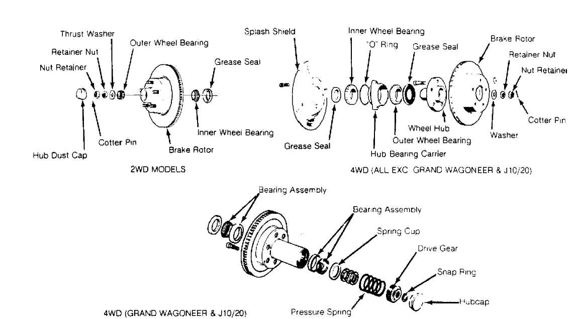
30211
Fig. 1: Exploded View Of 2WD Hub/Rotor Assembly & 4WD Hub/Bearing Carrier Assembly Courtesy of Chrysler Motors.
SHOCK ABSORBER
Removal & Installation
With
vehicle at normal riding height, remove nut, washer,
and rubber
grommet from top of shock absorber. Note component
locations for
reassembly reference.
Raise and
support vehicle. Remove lower shock mounting
bolts from axle
housing bracket. Remove shock absorber. Inspect units
for damage
or leakage. Replace shock absorbers in pairs only. To
install,
reverse removal procedure.
STEERING KNUCKLE
Removal
Raise and
support vehicle. Remove wheel assembly. Remove
brake caliper.
Suspend caliper with wire. Remove brake rotor or
hub/bearing
carrier assembly. See WHEEL BEARINGS in this article.
Remove
axle shaft from left side of axle housing. To
remove right axle
shaft, disconnect vacuum harness from shift motor.
Remove shift
motor and axle shaft from housing. Remove caliper anchor
plate
from steering knuckle.
On
each steering knuckle, remove ball joint stud cotter
pin and
retaining nuts. Using brass hammer, strike steering knuckle
at
ball joint stud bore area to loosen ball joint from
steering
knuckle.
Inspect
split ring seat in steering knuckle ball joint
stud bore for
damage. If damaged, use Split Ring Seat
Remover/Installer to
remove split ring seat.
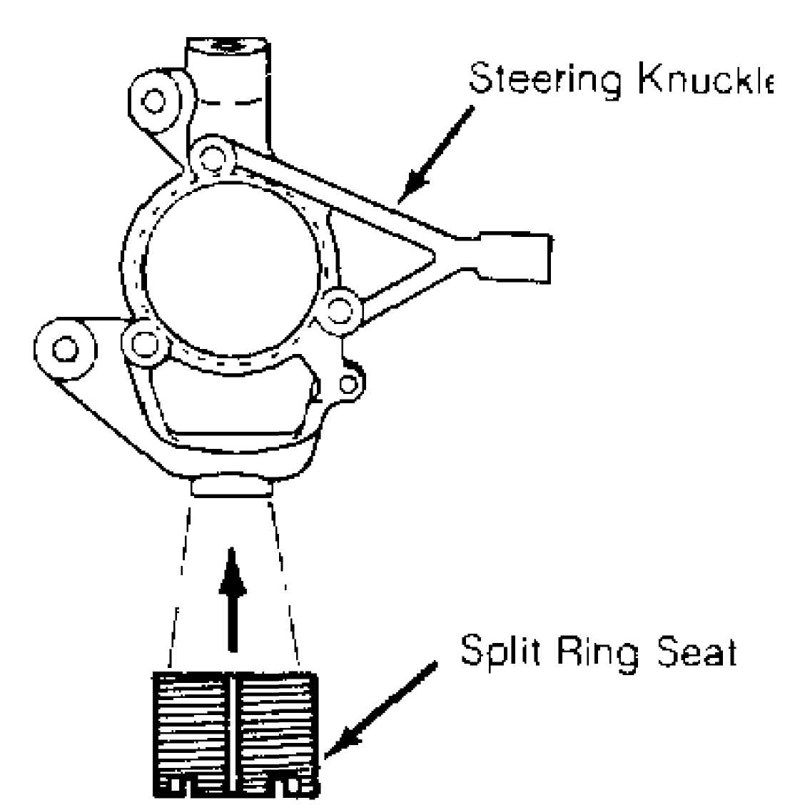
30212
Fig. 2: Determining Steering Knuckle Split Ring Seat Position Courtesy of Chrysler Motors.
Installation
If
split ring seat is replaced, ensure seat is adjusted
to
proper depth into steering knuckle ball joint stud bore. Using
split
ring seat remover /installer, install split ring seat to a
depth
of .206" (5.23 mm).
This
depth is measured from steering knuckle surface to
top
(notched edge) of split ring seat. See Fig. 2. To
install,
reverse removal procedures.
When
installing right axle shaft, ensure shift collar is
positioned on
intermediate shaft and axle shaft is fully engaged over
intermediate
shaft. Install shift motor. Ensure shift fork engages
with
collar. Tighten all bolts to specification.
UPPER & LOWER BALL JOINTS
Removal
Raise and
support vehicle. Remove wheel assembly. Inspect
upper and lower
ball joints for damage, torn grease seals or
excessive wear.
Replace as necessary.
Remove
steering knuckle assembly. See STEERING KNUCKLE in
this
article. Position Ball Joint Receiver (J-34503-1) over top of
upper
ball joint. Place Adapter (J-34503-3) in "C" Clamp
(J-34503).
Install "C" clamp, adapter and receiver.
Tighten "C" clamp screw to
remove
ball joint. See Fig. 3.
To
remove lower ball joint, position Ball Joint Receiver
(J-34503-1)
onto "C" Clamp (J-34503) and Adapter (J-34503-3) at
base
of clamp. See Fig. 3.
Install "C" clamp, adapter and
receiver.
Tighten "C" clamp to remove ball joint. See
Fig. 3.
Installation
1) Place
upper ball joint in position. Position Ball Joint
Installer
(J-34503-3) over new upper ball joint. Install Receiver
(J-34503-2)
and "C" clamp. Position clamp, and receiver against axle
housing bracket, over installer and ball joint. Tighten "C" clamp and fully seat ball joint. See Fig. 3.
2) To
install lower ball joint, position Ball Joint
Installer
(J-34503-12), "C" clamp and
Receiver (J-34503-4) See
Fig. 3. Tighten "C" clamp to install ball joint. Ensure ball joint is fully seated. Reverse removal procedures for remaining components. Tighten bolts to specification.
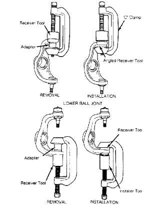
Fig. 3: Removing & Installing Upper & Lower Ball Joints Courtesy of Chrysler Motors.
UDPER BALL JOINT
COIL SPRING
Removal
Raise and
support vehicle. Remove wheel assembly. Place
reference mark on
drive shaft and front axle flange. Disconnect drive
shaft at
front axle. Place jack stand under axle housing. Disconnect
lower
control arms at axle housing.
Disconnect
stabilizer bar links and lower shock absorber
mounting
bolts at axle housing. Disconnect track bar at the sill
bracket
(if equipped). Disconnect center link at
pitman arm.
Lower axle
housing to relieve spring pressure. Remove
spring retainer
mounting bolt, then remove retainer and coil spring.
Note
component locations for reassembly reference.
NOTE: Coil springs are rated separately for each side of vehicle depending on optional equipment and type of service. Ensure springs are marked for installation in original positions.
Installation
Install
coil spring and spring retainer. Tighten retainer
mounting bolt.
Raise axle housing into position. Connect lower
control arms to
axle housing.
Install
lower shock absorber mounting bolts, center
link-to-pitman arm,
track bar-to-frame bracket and stabilizer bar
links-to-axle
housing. To complete installation, reverse removal
procedure.
LEAF SPRING
Removal & Installation
Raise and support vehicle. Raise axle assembly with jack to relieve spring tension. On Wrangler models, loosen stabilizer bar link nut. On all other models, remove stabilizer bar. Remove spring "U" bolts and plate. Disconnect front and rear shackles from frame. Lower spring assembly. To install, reverse removal procedure.
UPPER CONTROL ARM &
AXLE HOUSING PIVOT BUSHING
Removal
To remove
right side upper control arm for 6-cylinder
models, disconnect
right side engine mount. Raise and support engine
so rear control
arm mounting bolt clears exhaust pipe. On all models,
raise and
support vehicle.
Remove
upper control arm mounting bolt from axle housing.
Disconnect
control arm mounting bolt at frame rail. Remove upper
control
arm. Repeat procedure for opposite control arm. Inspect
control
arm for damage or distortion and replace as needed.
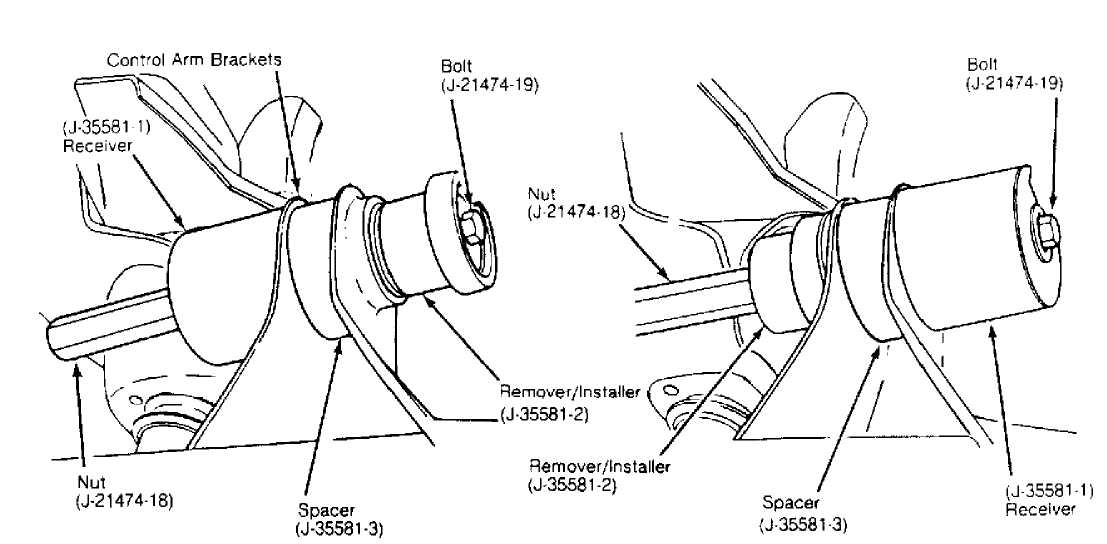
Check pivot bushings for excessive distortion,
deterioration or wear. If bushing replacement is necessary, install Spacer (J-33581-3) between ears of control arm bracket on axle housing. See Fig. 4.
NOTE: Spacer is not used on axle housings with solid control arm brackets.
CAUTION: Do not attempt to remove upper control arm pivot bushing without spacer. Tool is designed to support bracket and prevent distortion during bushing removal.
4) Install
Upper Control Arm Pivot Bushing Remover/Installer
Set
(J-35581, which must include Spacer J-35581-3, Remover/Installer
J-35581-2, Receiver J-35581-1, Bolt J-21474-19 and Nut J-21474-18) onto pivot bushing. See Fig. 4.
5) Rotate nut to press bushing from axle housing and into receiver. See Fig. 4. Once bushing is removed, remove bushing remover/installer set but leave spacer in position for new bushing installation.
Installation
Position
bushing on Remover/Installer (J-35581-2) and Nut
(J-21474-18).
Position bushing and installer components in
control
arm bracket. Assemble remaining installer components. See
Fig. 4.
Rotate
nut to press bushing into housing until fully
seated in bore. See
Fig. 4. Remove bushing installer
components.
Reverse removal procedure
for remaining components.
Removal Instailatiori
30214
Fig. 4: Removing & Installing Upper Control Arm Bushing Courtesy of Chrysler Motors.
LOWER CONTROL ARM & BUSHING
Removal
Raise and
support vehicle. Disconnect lower control arm
mounting bolts at
axle housing and frame brackets. Remove lower
control arm.
Inspect
control arm for damage and bushings for excessive
distortion or
wear. Replace control arm and/or bushings as necessary.
Installation
Position lower control arm in front and rear brackets. Install mounting bolts and nuts. Tighten mounting bolts to specification.
TRACK BAR
Removal
1) Raise and support vehicle. Remove cotter pin and mounting
nut at frame rail bracket. Remove retaining bolt at axle housing bracket. Remove track bar. Inspect track bar and bushing for damage or wear. Replace as needed.
2) If a snapping noise was noted at the front of vehicle, inspect track bar bushing inner sleeve for signs of wear. If sleeve has been contacting axle bracket, spread bracket flanges approximately 1/8" to provide space for a Hardened Washer Part No. (G2436163).
Installation
Position
track bar in axle housing bracket. Install
spacer/washer between
rear flange of bracket and track bar bushing.
DO NOT install
spacer/washer at the front of bracket.
Loosely
install mounting bolt. Ensure mounting bolt
passes through
spacer/washer. Connect track bar at frame rail
bracket. Tighten
ball stud mounting nut-to-frame rail bracket.
Tighten all bolts
to specification. Install new cotter pin.
FRONT STABILIZER BAR & LINKS
Removal
Raise and
support vehicle. Disconnect stabilizer bar from
upper portion of
stabilizer bar links. Note location of grommets and
washers for
reassembly reference.
Disconnect
stabilizer bar from frame rail brackets.
Remove stabilizer bar.
Inspect bar for damage. Check rubber grommets,
bushings and
bracket supports for distortion and/or deterioration.
Replace
worn components as necessary.
If
necessary, disconnect lower links at axle housing
brackets and
remove. Inspect links for damage and rubber grommets for
excessive
wear, distortion and/or deterioration. Replace components
as
necessary.
Installation
Lubricate
stabilizer bar bushings and grommets with
rubber grease. Connect
links to axle housing brackets. Install
washers and rubber
grommets on links.
Install
rubber bushings and brackets onto stabilizer bar
and connect
components to frame rails. Connect stabilizer bar to
stabilizer
links. Tighten mounting bolts to specification.
TORQUE SPECIFICATIONS
TORQUE SPECIFICATIONS TABLE
 Application Ft.
Lbs. (N.m)
Application Ft.
Lbs. (N.m)
Axle Shaft Nut 175 (237)
Brake Caliper Anchor Plate Bolt 70-85 (95-115)
Brake Caliper-to-Anchor
Plate Pin 25-35 (34-48)
Center Link-To-Pitman Arm Nut 25-45 (34-61)
Control Arm To-Axle
Housing Bracket Bolt
Lower 118-148 (160-200)
Upper 48-63 (65-85)
Upper Frame Bolt 59-74 (80-100)
Drive Shaft "U" Joint Strap Bolt 12-17 (16-23)
Lug Nuts 75 (102)
Shock Absorber
Lower Mounting Bolt
W/Coil
Springs 12-16 (16-22)
W/Leaf Springs 35-55 (48-75)
Upper Nut
Grand Wagoneer 25-40 (34-54)
All Others 14 (19)
Spring-to-Frame Bracket Bolt 95-115 (129-156)
Spring-to-Shackle Bolt 85-105 (115-142)
Spring "U" Bolt
9/16" x 18 85-105 (115-142)
1/2" x 20 45-65 (61-88)
Stabilizer Bar Mounting Bolt
Grand Wagoneer 27-45 (37-61)
All Others Stabilizer Bar Bracket-to-Frame Rail
W/Coil Springs 48-63 (65-85)
W/Leaf Springs 25-35 (34-48)
Stabilizer Bar Link-to-Axle
Bracket Bolt 59-81 (80-110)
Stabilizer Bar Link-to-Axle
Plate Nut 35-55 (48-75)
Stabilizer Bar-to-Link Bolt 35-55 (48-75)
Stabilizer Bar-to-Link Nut
Grand Wagoneer 48-62 (65-84)
All Others 23-31 (31-42)
Steering Knuckle-to-Hub Bolt 75 (101)
Steering Knuckle-to-Ball Joint Mounting Nut
W/Coil Springs 65-85 (88-115)
W/Leaf Springs 87-113 (118-153)
Steering Knuckle-to-
Tie Rod Nut 25-45 (34-61)
Track Bar Bracket-to-Frame
Rail Bolt 66-81 (90-110)
Track Bar Bracket-to-Axle Nut 66-81 (90-110)
Track Bar-to-Frame Bracket Nut 30-40 (41-54)