EGR SYSTEM
1988 Jeep Cherokee
1983-88 Exhaust Emission Systems JEEP EXHAUST GAS RECIRCULATION
DESCRIPTION
Purpose of the Exhaust Gas Recirculation (EGR) system is to limit formation of oxides of nitrogen (NOx) emissions. This is done by reducing high peak combustion temperatures at which NOx is formed. By reintroducing some exhaust gas back into combustion chamber, high temperatures are avoided. Thus NOx emissions formation is reduced.
System consists of vacuum-operated EGR valve and coolant temperature override (CTO) switch. In addition, some models are equipped with air cleaner-mounted thermal vacuum switch (TVS), and some are equipped with an EGR vacuum dump valve.
OPERATION
When the EGR valve receives vacuum signal, through the CTO switch, EGR valve opens and meters gases from exhaust manifold into intake manifold. Individual component operation is as follows:
EGR VALVE
EGR valve is mounted on intake manifold. Exhaust gas is drawn from exhaust crossover passage or exhaust manifold. Two types of EGR valves are used: valve without backpressure sensor and valve with integral backpressure sensor.
EGR Valve W/O Integral Backpressure Sensor
EGR valves are calibrated by use of different shapes of valve pintles or orifices. Valve is normally held closed by spring (above diaphragm). Valve opens by overcoming spring tension when vacuum is sensed through coolant temperature override switch (CTO) and backpressure sensor (if equipped).
EGR Valve W/Integral Backpressure Sensor
Calibration is accomplished by use of different diaphragm spring loads and flow control orifices. This integral type unit combines EGR valve and backpressure sensor functions into one component. Restrictor plate is required with some engines.
Exhaust gas exerts backpressure inside exhaust manifold whenever engine is running. This pressure is conducted through hollow pintle stem into EGR diaphragm control chamber. If this pressure is great enough to overcome spring tension against diaphragm, diaphragm is moved against bleed valve and exhaust gas flow begins.
COOLANT TEMPERATURE OVERRIDE (CTO) SWITCH
Coolant temperature override (CTO) switch is located in coolant passage at cylinder head or coolant passage at intake manifold.
Inner port of switch is connected to EGR port on intake manifold and outer port is connected to EGR valve, or EGR-TVS. Switch opens at a preset temperature. Below these temperatures, no EGR is possible.
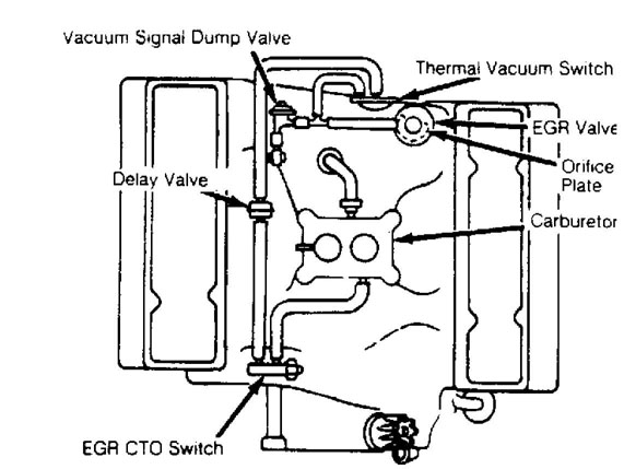
Fig. 1: Jeep V8 Carbureted Engine EGR System Courtesy of Chrysler Motors.
THERMAL VACUUM SWITCH (TVS)
Used only on carbureted 6-cylinder and V8 engines, this switch is located in air cleaner and acts as on-off switch for EGR system. It is controlled by ambient temperature in air cleaner. Switch controls vacuum passage between CTO switch and EGR valve. Below preset temperature, TVS blocks passage of vacuum delaying EGR operation and improving cold driveability.

Fig. 2: Jeep 6-Cylinder Carbureted Engine EGR System Courtesy of Chrysler Motors.
EGR DUMP VALVE
Used on some models, EGR dump valve is connected in series with vacuum source and EGR valve. Valve is used to eliminate EGR function at low vacuum levels. When vacuum drops below predetermined level, valve "dumps" vacuum rather than allowing it to flow to EGR
valve.
FORWARD DELAY VALVE
Forward delay valve is located between EGR CTO switch and EGR valve. It modifies initial vacuum signal applied to EGR valve by delaying full vacuum force.
TESTING
EGR VALVE
Valve Opening Test
With engine at normal operating temperature and at idle,
rapidly open and close throttle. Open throttle sufficiently to obtain
at least 1500 RPM. Movement should be noticed in EGR diaphragm.
If diaphragm does not move, probable causes are: faulty
vacuum signal to EGR, defective EGR diaphragm or defective
backpressure sensor diaphragm (if equipped), or leaks in vacuum lines
or connections.
Valve Closing Test
With engine at normal operating temperature and at idle,
manually depress EGR valve diaphragm. RPM should immediately drop,
indicating that EGR valve is not leaking and had been properly cutting
off exhaust gas flow at idle.
If there is no change in RPM and engine is idling
properly, exhaust gases are not reaching combustion chamber. Check for plugged passage between EGR valve and intake manifold.
3) If engine idles poorly and RPM is not greatly affected by
manually moving diaphragm up, EGR valve is not closing off exhaust gas
flow. Check for carbon between pintle, leaking EGR valve gasket or bad
EGR valve.
COOLANT TEMPERATURE OVERRIDE (CTO) SWITCH
NOTE: Engine coolant temperature must be below 100F (38C) to perform this test.
1) Check vacuum lines for leaks and correct routing.
Disconnect vacuum line at backpressure sensor (if equipped) or at EGR valve, and attach this line to vacuum gauge.
Operate engine at 1500 RPM. No vacuum should be indicated
on gauge. If vacuum is shown, replace CTO switch.
Idle engine until coolant temperature exceeds 100F (38C)
on 4-cylinder engines, or 115F (46C) on 6-cylinder and V8 engines.
Raise engine speed to 1500 RPM. Ported vacuum should be
shown on gauge. If not, replace CTO switch.
DUMP VALVE
With engine at normal operating temperature, remove dump
valve vacuum hose from manifold and plug manifold connection.
Raise engine speed to 2000 RPM. Vacuum should be present
at exhaust ports on bottom of valve. If not, replace valve.
Reconnect vacuum hose to manifold and raise engine speed
to 2000 RPM. No vacuum should be felt at exhaust ports on bottom of
valve. If vacuum is present, replace valve.
THERMAL VACUUM SWITCH (TVS)
With the air cleaner temperature below 40 F (-4C),
disconnect vacuum hoses from TVS and connect vacuum source to large
outlet.
Apply vacuum to TVS. TVS should hold vacuum. If not,
replace TVS.
Start engine and warm air cleaner to 55F (13C), or
greater. TVS should not hold vacuum. If it does, replace TVS.
