TRANSFER CASE - OVERHAUL (207/231)
1988 Jeep Cherokee
1983-96 TRANSFER CASES
Chrysler Corp., GM Corp., Jeep - New Process 207 & 231
Dodge; B1500 & Dakota
GMC/Chevrolet; "T" Series (Blazer & Jimmy)
Jeep; Cherokee, Comanche, Grand Cherokee, Wagoneer, Wrangler
IDENTIFICATION
Transfer case can be identified by an I.D. tag, located on rear case. I.D. tag provides model number, serial number and low range ratio. Date of manufacture is the serial number (I.D. number). This information is necessary when ordering parts.
DESCRIPTION
Model 231 transfer case is a part time, chain-driven, 4-position unit with 2-piece aluminum case. Torque input in 4WD high and low range is undifferentiated. 2WD operation is achieved by a vacuum shift motor. Shift motor disconnects right front axle when 2WD is selected. Vacuum shift motor is controlled by a vacuum switch located on front of transfer case and actuated by shift sector.
ADJUSTMENTS
GEARSHIFT LINKAGE
Chrysler Corp.
Shift transfer case to 2H position. Raise and support vehicle. Loosen lock bolt at trunnion. Ensure linkage rod slides freely in trunnion. Verify transfer case range lever is fully engaged in 2H position. Tighten lock bolt at trunnion. Lower vehicle. Check shift linkage operation. Ensure transfer case shifts into and operates properly in all gear ranges.
General Motors
Remove shift lever knob retainer. Remove shift lever knob. Remove floor console. Place shift lever in Neutral. Pry control cable end from shift lever. Loosen control cable lock nut. Check transfer case to ensure it is in Neutral. Ensure shift lever is in Neutral. Turn shift lever end of cable in or out as needed until it is aligned with shift lever. Install control cable on shift lever. Tighten control cable lock nut.
Jeep
Shift transfer case to 4L position. Raise and support vehicle. Loosen lock bolt at trunnion. Ensure linkage rod slides freely in trunnion. Verify transfer case range lever is fully engaged in 4L position. Tighten lock bolt at trunnion. Lower vehicle. Check shift linkage operation. Ensure transfer case shifts into and operates properly in all gear ranges.
TESTING
VACUUM SWITCH
Shift to 2WD position. Locate vacuum switch on front of
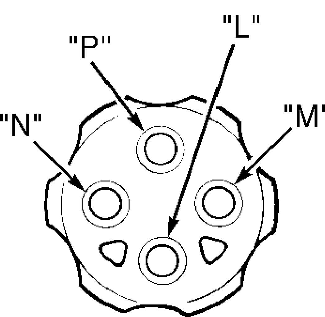
transfer case. Apply 15 in. Hg vacuum to "L". See Fig. 1. Vacuum should be present at "M". Connect a vacuum gauge to "N". Shift to 4WD position. Apply vacuum to "L". Vacuum should be present at "N". If switch fails any test, replace switch.

92F13081
Fig. 1: Testing Vacuum Switch Courtesy of Chrysler Corp.
TROUBLE SHOOTING
SYMPTOM DIAGNOSIS
Will Not Shift Or Difficult To Shift Into Gear Vehicle speed too high; slow vehicle to 2-3 MPH to shift. Vehicle operated too long on dry paved surface; stop vehicle and place in Reverse or Neutral to relieve driveline torque. Ensure transfer case external linkage is not binding. Ensure correct fluid is used. Internal parts may be worn or damaged.
Noisy In All Gears
Check fluid level. Ensure correct fluid is used. If fluid is okay, locate possible internal mechanical problem.
Jumps Out Of Gear Or Noisy In 4WD
Transfer case not completely in gear; check shift linkage. Range fork damaged. Shift fork pads are worn or shift fork binding. Low range gear worn.
Fluid Leaking From Vent Or Seals
Transfer case overfilled. Vent plugged. Output shaft seals are damaged or not installed properly.
ON-VEHICLE SERVICE
FRONT OIL SEAL
Removal & Installation
1) Mark front drive shaft and flange for installation
alignment reference. Remove front drive shaft. Remove flange. Discard washer and nut. Using a screwdriver, carefully remove oil seal. Ensure seal contact surface is clean.
2) Apply
ATF to seal lip and flange seal surface. Install NEW
oil seal.
Install flange and NEW washer and nut. Tighten nut to
specifications.
See TORQUE SPECIFICATIONS. Install front drive shaft
using
alignment marks. Check transfer case fluid.
EXTENSION HOUSING OIL SEAL & BUSHING
Removal & Installation
1) Mark rear drive shaft and flange for installation
alignment reference. Remove rear drive shaft. Tap extension housing in a clockwise direction and remove extension housing. DO NOT pry on extension housing. Using a screwdriver, remove oil seal from extension housing.
2) Using
bushing driver, replace bushing in extension
housing.
Install NEW extension housing oil seal. Apply silicone
sealant
to extension housing mating surface. Install extension
housing. To
complete installation, reverse removal procedure.
REMOVAL & INSTALLATION
TRANSFER CASE
Removal
Shift
transfer case into 4H and disconnect battery
negative cable.
Raise vehicle, remove skid plate and drain fluid.
Mark front
and rear output shaft yokes to drive shafts for
reassembly
reference. Support transfer case and remove rear
crossmember.
Remove drive shafts.
Disconnect
vehicle speed sensor electrical connector and
vacuum (hoses)
harness at transfer case. Remove shift lever or linkage
rod from
case. Remove transfer case attaching bolts. Remove transfer
case
from vehicle.
Installation
Clean all
old gasket material from transmission and
transfer case mating
surfaces. Position NEW gasket on transfer case
with orientation
tab at upper left bolt hole.
Install
transfer case, aligning splines of input shaft
with transmission.
Slide transfer case forward until seated against
transmission.
Install transfer case attaching bolts and tighten to
specification.
See TORQUE SPECIFICATIONS. Install rear crossmember.
Attach
shift lever and connect speed sensor electrical
connector and
vacuum harness at transfer case. Using reference marks
made
during removal, reinstall front and rear drive shafts.
Refill
transfer case. Install skid plate and lower vehicle.
Connect negative
battery cable. Road test vehicle.
TRANSFER CASE DISASSEMBLY
Remove
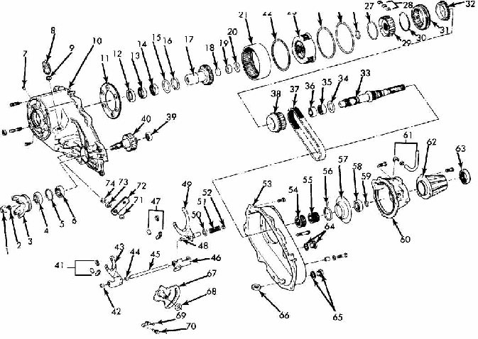
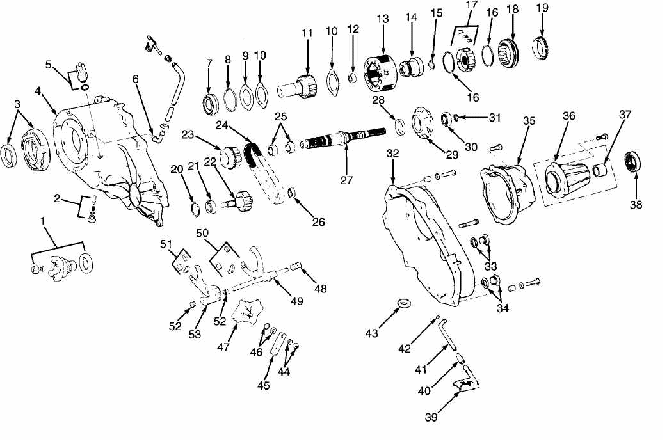
front companion yoke. See Fig. 2 or 3.
Discard
washer and
nut. Shift transfer case to 4L and remove extension
housing.
Remove rear bearing snap ring. Using 2 screwdrivers
under
each tab, remove retainer
housing. Remove rear case and oil pump as an
assembly.
Remove
oil pump pick-up screen and tube from rear case.
Remove
oil pump. Remove "O" ring from
oil pump and discard. DO NOT
separate oil pump halves. Pump must
be replaced as an assembly if
necessary.
Remove
mode spring. Using a soft hammer, tap front output
shaft upward
and remove with drive chain as an assembly. Remove
mainshaft,
mode fork and shift rail as an assembly. Remove mode fork
and
shift rail from synchronizer sleeve.
Mark
synchronizer sleeve position for reassembly
reference. Remove
synchronizer sleeve from mainshaft. Remove
synchronizer hub snap
ring. Remove synchronizer hub, stop ring and
drive sprocket.
Slide range fork pin out of sector.
Remove
range fork and shift hub as an assembly. Remove
range lever from
sector shaft. Remove shift sector, bushing and "O"
ring.
Remove shift detent pin, spring and plug. Remove front
bearing
retainer. Remove input gear snap ring.
Press
input and low range gear assembly from input gear
bearing. Remove
low range gear snap ring. Remove input gear retainer,
thrust
washers and input gear from low range gear.
Remove all
oil seals. Remove magnet from front case.
Remove front bearing
snap ring. Using a plastic hammer, remove front
bearing. Press
input gear bearing from front case.
Using
slide hammer and internal puller, remove input gear
pilot
bearing. Press bearings from drive sprocket. Using internal
puller
and slide hammer, remove output shaft rear bearing.
24 25 26
Front Companion Flange Nut
Front Companion Flange Seat
Front Companion Flange
Front Output Shaft Seal
Snap Ring
Front Output Shaft Bearing
Case Plug
Vacuum Switch
Gasket
Front Case
Low Range Lock Plate
Input Gear Seal
Input Gear Front Bearing
Input Gear Rear Bearing
Thrust Bearing Washer
Input Gear Thrust Bearing
Input Gear
Input Gear Cup Plug
Mainshaft Pilot Bearing
Planetary Thrust Washer
Annulus Gear
Front Thrust Ring
Planetary Gear
Rear Thrust Ring
Planetary Retaining Ring
Snap Ring
Synchronizer Front Spring
Synchronizer Struts
Synchronizer Hub
Synchronizer Rear Spring
Synchronizer Sleeve
Synchronizer Stop Ring
Mainshaft
Thrust Washer
Drive Sprocket Rear Bearing
Drive Sprocket Front Bearing
Drive Chain
Drive Sprocket
Front Output Shaft Bearing
Front Output Shaft
Range Fork Pads
Range Fork Front Bushing
Range Fork
Range Fork Rear Bushing
Shift Rail
Shift Rai! Bracket
Mode Fork Pads
Mode Fork Front Bushing
Fig. 2: Exploded View Of Transfer Case (Model 207) Courtesy of Chrysler Corp.
 Mode
Fork
Mode Fork Cup
Mode Fork Spring
Mode Fork Rear Bushing
Rear Case
Oil Pump
Speedometer Drive Gear
Pump Housing Seal
Oil Pump Housing
Mainshaft Rear Bearing
Rear Bearing Snap Ring
Rear Retainer
Vent Assembly
Extension Housing
Extension Housing Seal
Fill Plug
Drain Plug
Magnet
Shift Sector
Spacer
Sector Detent Spring
Detent Spring Bolt
Range Lever Nut
Range Lever
"O" Ring Retainer
"O" Ring
95H2941C
 Front
Companion Yoke,
Nut, Washer & Seal
Detent Plug, Spring & Pin
Front Retainer & Seal
Front Case
Vacuum Switch & Seal
Vent Assembly
Input Gear Bearing & Snap Ring
Low Range Gear Snap Ring
Input Gear Retainer
Low Range Gear Thrust Washers
Input Gear
Input Gear Pilot Bearing
Low Range Gear
Range Fork Shift Hub
Synchronizer Hub Snap Ring
Synchronizer Hub Springs
Synchronizer Hub & Inserts
Synchronizer Sleeve
Synchronizer Stop Ring
Snap Ring
Output Shaft Front Bearing
Front Output Shaft
Drive Sprocket
Drive Chain
Drive Sprocket Bearings
Output Shaft Rear Bearing
Mainshaft
Oil Seal
Oil Pump Assembly
Rear Bearing
Snap Ring
Rear Case
Fill Plug
Drain Plug
Rear Retainer
Extension Housing
Bushing
Oil Seal
Oil Pick-Up Screen
Tube Connector
Oil Pick-Up Tube
"O" Ring
Magnet
Range Lever Nut & Washei
Range Lever
"O" Ring & Seal
Sector
Mode Spring
Mode Fork
Mode Fork Pads
Range Fork Pads
Range Fork Bushings
Range Fork
92 H13083
Fig. 3: Exploded View Of Transfer Case (Model 231) Courtesy of Chrysler Corp.
CLEANING & INSPECTION
Clean all parts with solvent. Dry with compressed air. Replace all oil seals, "O" rings and snap rings. Check all parts for wear or damage. Replace all worn or damaged parts. If low range annulus gear inside front case is damaged or worn, front case and gear must be replaced as an assembly. Replace oil pump as an assembly if any part is damaged or worn.
TRANSFER CASE REASSEMBLY
NOTE: When installing bearings, ensure bearing bores are aligned with oil feed holes.
1) Lubricate all parts with Dexron III before installing.
Install output shaft front bearing with NEW snap ring. Install output shaft oil seal in front case. Install snap ring on NEW input gear bearing. See Fig. 2 or 3.
Press
input gear bearing so snap ring is seated against
case. Using
press, install NEW input gear pilot bearing. Assemble low
range
gear, input gear, thrust washers and retainer.
Install
snap ring. Ensure snap ring is seated in low range
gear groove.
Start input gear shaft into bearing in front case. Press
input
shaft gear into bearing.
CAUTION: DO NOT press against end surfaces of gear. Failure to use proper size tool could lead to gear case or thrust washer damage.
Install
input gear snap ring. Install oil seal in front
bearing retainer.
Apply a 1/8" bead of silicone sealant
to retainer
mating surface. Align oil
channel in retainer with oil feed hole in
case. Install retainer
on case. Tighten bolts to specification.
Install
sector shaft "O" ring and
bushing. Install range
sector in case. Install range lever and
nut. Install detent, detent
spring and
plug. Tighten to specification. See TORQUE SPECIFICATIONS.
Install
NEW pads and fork rail bushings on range fork. Install range
fork
and shift hub.
Ensure
range fork pin is engaged with range sector slot.
Press
front bearing in drive sprocket until bearing is flush with
bore
edge. Install rear bearing until bearing is 3/16"
below bore edge. See
Fig.
4.
Install
inserts and spring in synchronizer hub. Install
sprocket on
mainshaft. Install synchronizer stop ring
on mainshaft.
Ensure stop ring is
seated. Install synchronizer hub on mainshaft.
Align
and seat hub inserts on stop ring lugs. Install synchronizer
hub
snap ring.
Install
synchronizer sleeve on hub. Ensure sleeve is
positioned
so beveled spline ends are facing stop ring. Ensure sleeve
tooth
is aligned (centered) over each synchronizer strut. Gear clash
will
occur if strut and sleeve teeth are misaligned. Install NEW pads
on
mode fork. Engage mode fork in synchronizer sleeve.
Install
mainshaft and fork assembly in case. Ensure mode fork
shift rail is
seated in both range fork
bushings.
Install
output shaft and drive chain assembly. Install
mode spring on
shift rail. Using bearing driver, install output shaft
rear
bearing. Lubricate bearing after installation. Install seal in
oil
pump feed housing. Install oil pump in housing. Tighten
to
specification.
Install
oil pick-up tube "O" ring in oil
pump. Prime oil
pump by pouring ATF into pump through pick-up
tube opening. Install
oil pump and pick-up tube in case. Ensure
oil screen is properly
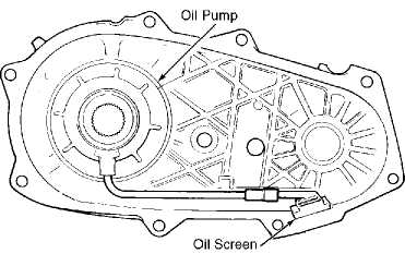
positioned. See
Fig. 5. Install magnet in front case.
Apply 1/8" bead
of
silicone sealer to front case. Install rear case. Tighten
to
specification. See TORQUE
SPECIFICATIONS. Ensure mainshaft splines are
engaged
with oil pump inner gear and a washer is used on bolts at
dowel
locations.
Install
rear bearings in retainer. Apply 1/8" bead
of
silicone sealer and install retainer
to case. Install rear retainer
snap ring. Install extension
housing. Install front companion yoke.
Install NEW gasket on
vacuum switch. Install vacuum switch in case.
Fill transfer case
with Dexron III.

92G13082
Fig. 4: Installing Drive Sprocket Bearings Courtesy of Chrysler Corp.

Fig. 5: Identifying Oil Pump Screen Position Courtesy of Chrysler Corp.
TORQUE SPECIFICATIONS
TORQUE SPECIFICATIONS TABLE
 Application Ft.
Lbs. (N.m)
Companion Flange Nut
Chrysler Corp 130-200 (176-271)
General Motors 80 (108)
Jeep 110 (149)
Detent Plug
General Motors 11 (15)
Chrysler Corp. & Jeep 15 (20)
Drain & Fill Plug 30-40 (41-54)
Extension Housing Bolt 20-25 (27-34)
Front Bearing Retainer Bolt
Chrysler Corp. & Jeep 16 (22)
General Motors 14 (19)
Front Case-to-Rear Case Bolt Chrysler Corp.
Flange Head Bolt 35-45 (47-61)
All Other Bolts 20-25 (27-34)
General Motors 23 (31)
Jeep 20-25 (27-34)
Range Lever Nut 15-20 (20-27)
Rear Bearing Retainer Bolt 20-25 (27-34)
Rear Crossmember 30 (41)
Shift Lever Lock Bolt 10 (14)
Speed Sensor Bolt 23 (31)
Transfer Case-to-Transmission Nut 26 (35)
Vacuum Switch
Chrysler Corp 15-25 (20-34)
General Motors 17 (23)
Jeep 20-25 (27-34)
INCH Lbs.
Control
Cable Lock Nut 18 (2)
VACUUM DIAGRAMS
For vacuum diagrams, refer to appropriate VACUUM DIAGRAMS article in the ENGINE PERFORMANCE section.