HEATER SYSTEM
1988 Jeep Cherokee
1988 HEATER SYSTEMS Jeep
DESCRIPTION
Jeep vehicles use a blend-air type heater system. Wrangler models have a constant flow type system with engine coolant continuously flowing through heater core. Cherokee and Comanche use heater control valves. Coolant flow to heater core on these models can be stopped or diverted.
On all models, temperature of heated air entering passenger compartment is controlled by regulating amount of air flowing through heater core and then blending it with a controlled amount of cool air by-passing heater core.
CONTROL PANEL OPERATION
Control panel on all models includes fan switch, sliding temperature control lever and sliding mode lever.
DEFROSTER CONTROL
Defroster control operates heater housing door regulating heater and defroster operation by directing flow of air through defroster hose or floor outlets. When control knob is pushed in, blended air will enter passenger compartment through floor heat duct. When control is pulled completely out, door directs all heated air to windshield defroster outlets. Any intermediate position divides air flow between windshield and floor outlets.
TEMPERATURE CONTROL LEVER (CHEROKEE, COMANCHE & WRANGLER)
Lower control lever operates blend-air door in heater core housing. At full right position, all air is directed through heater core, providing maximum heat flow. At full left position, all air is directed around heater core providing fresh air. Control can be set in any intermediate position to provide a blend of heated and unheated air. With control lever in "COOL" position, water valve will close (except Wrangler). Mode control lever must be in "HEAT" or defroster mode before any air can enter vehicle.
MODE CONTROL LEVER (CHEROKEE & COMANCHE)
Mode control lever includes "BI-LEVEL", "VENT", "HEAT" and "OFF" positions. At far end of scale, a symbol for defroster indicates defrost position. In "BI-LEVEL" position, a mixture of floor heat and defroster air is obtained.
FAN CONTROL
Fan control is a 4-position control switch, regulating blower motor and air flow for heat and defrost. Switch has "LOW", "HIGH" and 2 intermediate positions. Fan will remain on unless mode lever is placed in "OFF" position.
CONTROL CABLES ADJUSTMENT
CHEROKEE & COMANCHE
The heater control cable is retained to blend air door lever with a retaining clip and a self-adjusting clip. During installation, self-adjusting clip will locate cable properly when cable is snapped into position on lever.
WRANGLER
The only adjustable cables are the vent door control cables. Since the left cable operates the right cable, the cables must be installed and adjusted in the proper order to maintain the self adjusting mechanism.
With cables connected to heater control panel, connect only the right vent door cable. Open and close right vent door one time, using heater control panel. Connect left side cable and ensure that both vent doors open at the same time.
Blower Motor
17581
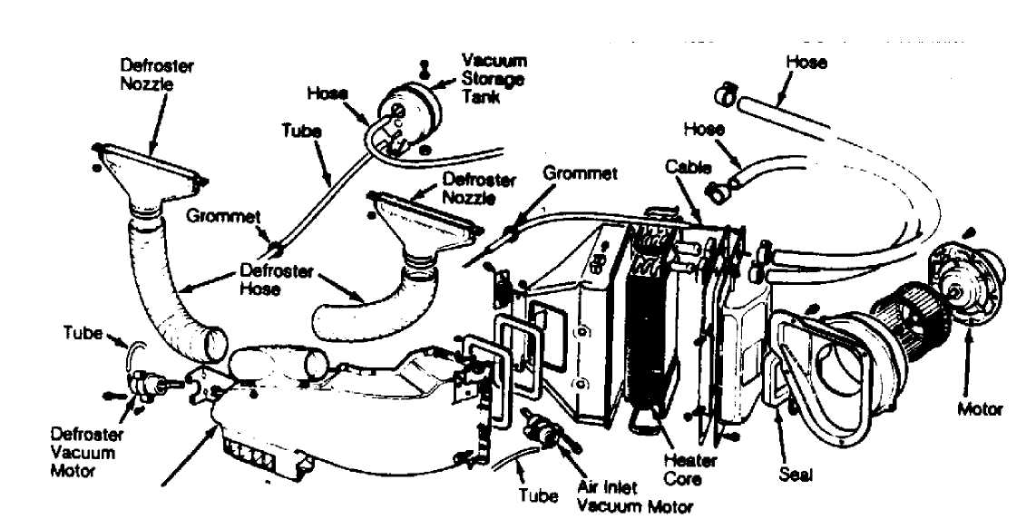
Fig. 1: Heater & Defroster Components (Wrangler) Courtesy of Chrysler Motors.
 Heatw
and Defroster Damper Housing
Heatw
and Defroster Damper Housing
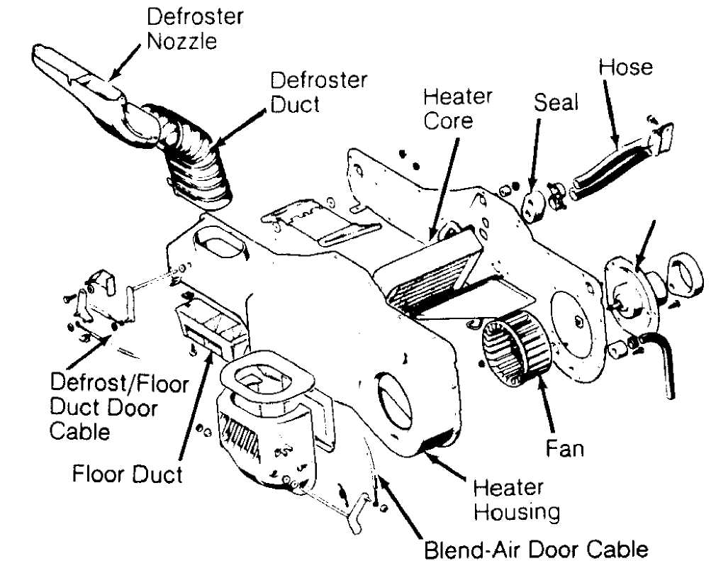
Fig. 2: Typical Heater & Defroster Components Courtesy of Chrysler Motors.
BLOWER MOTOR R & I
NOTE: On Cherokee and Comanche, blower motor and fan are removed from engine compartment.
Removal & Installation
Remove
heater core housing assembly. On all models, remove
blower
motor electrical connectors. Detach
screws retaining blower
motor assembly to heater housing. Remove
blower motor and fan
assembly. On
Cherokee and Comanche, detach fan retaining clip from fan
hub,
if necessary. Remove fan from motor shaft.
To
install, reverse removal procedure. If removed, ensure
ears of
retaining clip are over flat surface on motor shaft. Check
blower
motor and heater operation.
CONTROL PANEL R & I
Removal & Installation
Disconnect
battery ground. On Cherokee, remove lower
instrument
panel. On all models, remove instrument panel bezel. On
Cherokee,
remove clock and radio (if equipped).
On all
models, remove heater control panel attaching
screws. Pull out
control panel and disconnect vacuum hoses, wires and
cables.
Note locations for reassembly reference. Remove control panel.
To
install, reverse removal procedure.
CONTROL CABLES R & I
REMOVAL (CHEROKEE & COMANCHE)
Remove control panel. Detach cable from heater control panel.
Remove retaining clip and cable self-adjusting clip from blend-air door lever at bottom of blower housing. Remove cable by squeezing tabs with needle nose pliers. Do not break housing.
INSTALLATION
To install, connect cable self-adjusting clip to blend-air door lever, then snap cable into position. Install retaining clip onto blend-air door lever. Route cable to A/C-heater control panel and connect. Install control panel.
REMOVAL & INSTALLATION (WRANGLER)
Disconnect
cables from vent doors. Disconnect cables from
heater control
panel levers. Remove cables by squeezing tabs with
needle nose
pliers.
Connect
and adjust cables as described in ADJUSTMENTS
section of this
article
HEATER CORE R & I
REMOVAL & INSTALLATION (CHEROKEE & COMANCHE)
Disconnect
battery ground. Drain cooling system.
Disconnect heater hoses at
heater core inlet and outlet tubes.
Disconnect
blower motor wires and vent tube. Remove console (if
equipped).
Remove lower instrument panel.
Disconnect
electrical connectors from blower motor
resistors. Disconnect
vacuum hose at vacuum motor. Cut plastic
retaining strap holding
blower housing to heater core housing.
Disconnect
and remove heater control cable. Detach clip at
rear
of blower housing flange and remove retaining screws.
Remove
housing mounting nuts from studs on
engine compartment side of dash
panel.
Remove right kick panel.
Remove
instrument panel support bolt. Gently pull on right
side of dash,
then rotate housing downward and toward rear of vehicle
to
disengage housing studs from dash panel. Remove blower
housing.
Detach retaining screws and remove heater core by
pulling it straight
out of housing.
To
install, reverse removal procedure. Ensure seal is
cemented in
place to prevent movement when blower assembly is
installed.
Connect heater hoses and fill cooling system.
REMOVAL & INSTALLATION (WRANGLER)
Disconnect
battery ground. Drain about 2 quarts of
coolant
from radiator. Disconnect heater hoses at heater core
inlet and outlet
tubes. Disconnect vent
door cables. Disconnect blower motor wires.
Disconnect
defroster duct.
Remove
nuts attaching heater housing studs to engine
compartment side of
dash panel. Remove heater housing assembly by
tilting it
downward, to disengage it from defroster duct.
Pull
heater housing rearward and out from under instrument
panel.
Remove heater housing cover from heater housing assembly.
Remove
heater core from housing.
HEATER SYSTEM OPREATION CHART & VACUUM DIAGRAM
HEATER SYSTEM OPERATION TABLE
 I I I
I I I I I
I I I
I I I I I
I MODE I I I I I I I
|
LEVER POSITION |
AIR DISCHARGE |
BLOWER SPEEDS |
PANEL DOOR |
FLOOR DOOR |
DEFROST DOOR |
WATER VALVE |
|
Off |
Closed |
None |
Closed |
Closed |
Closed |
Closed |
|
Vent |
Panel Registers |
4 |
Open |
Closed |
Closed |
Closed |
|
Bi-Level |
Panel Registers and Floor With Def. Bleed |
4 |
Open |
Open |
Bleed |
Open (1) |
|
Heat |
Floor With Def. Bleed |
4 |
Closed |
Open |
Bleed |
Open (1) |
|
Def. |
Defroster |
4 |
Closed |
Closed |
Open |
Open(1) |
|
(1) - Water valve closes in full "COOL" temperature lever position. |
||||||
HEATER CONTROL SYSTEM VACUUM SCHEMATIC
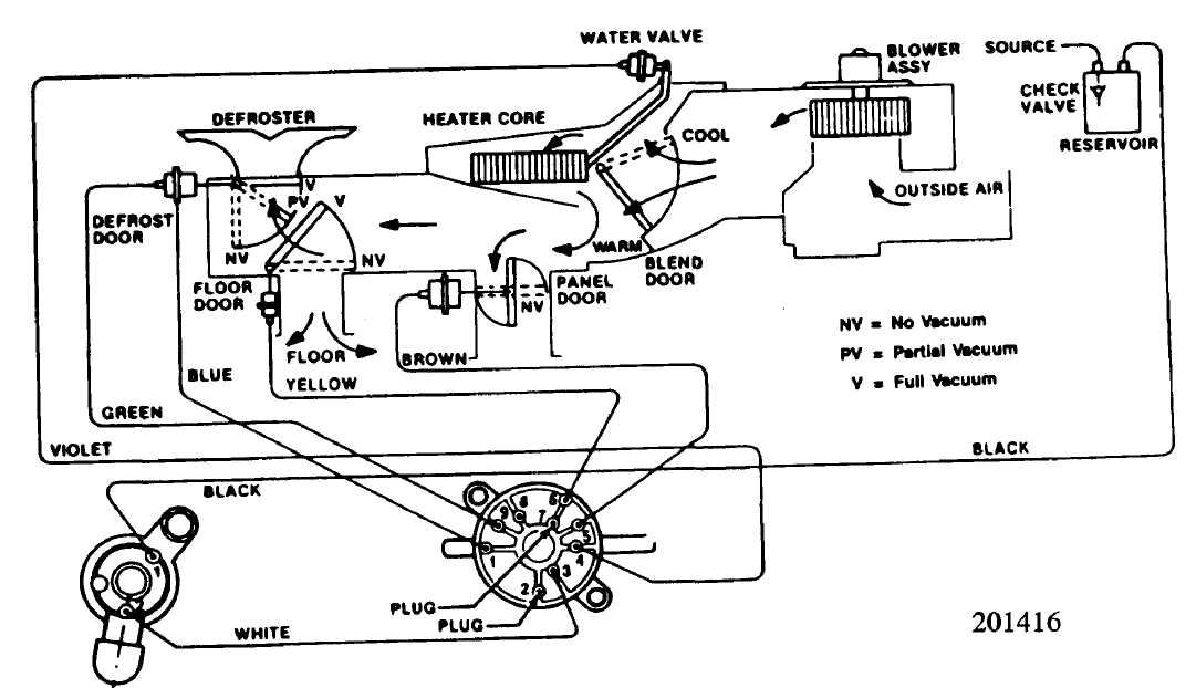
Fig. 3: Heater Control System Vacuum Diagram
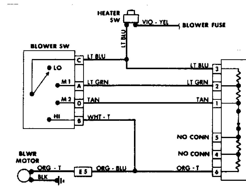
WIRING DIAGRAMS
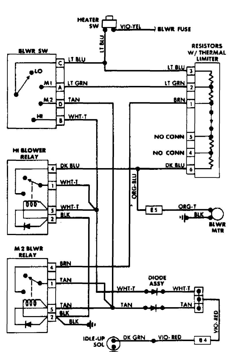
 Fig.
4: Heater Wiring Diagram
(Comanche Diesel)
Fig.
4: Heater Wiring Diagram
(Comanche Diesel)
«SISTORS W/ THERMAL LIMITIR
Fig. 5: Heater Wiring Diagram (Comanche Gas)

 Fig.
6: Heater Wiring Diagram (Wrangler)
Fig.
6: Heater Wiring Diagram (Wrangler)