ALTERNATOR - DELCO W/INTEGRAL REGULATOR
1988 Jeep Cherokee
1988 Alternators & Regulators
DELCO-REMY WITH INTEGRAL REGULATOR
Jeep
DESCRIPTION
There are 2 types of alternators used on these vehicles. The
12SI and 17SI series (Systems Integral), means alternator with builtin
regulator. All 12SI alternators have "Y" stator windings, while all
17SI have delta windings.
The CS130 (Charging System) alternators have a high amperage
output. This alternator does not have a diode trio.
IDENTIFICATION
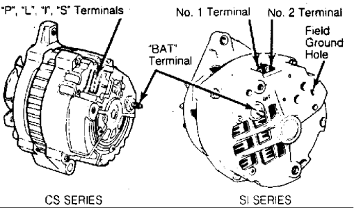
Fig. 1: Alternator Terminal Identification & Locations
"S" terminal is optional on CS130.
OPERATION
CS SERIES
Regulator voltage varies to compensate for temperature.
Voltage is regulated by controlling rotor field current. Regulator
switches rotor field current "on" and "off" at a fixed frequency of
approximately 400 cycles per second.
By controlling "on" and "off" time correct system voltage can
be obtained. During high speeds "on" time may be 10 percent and "off"
time 90 percent. During low speeds with high electrical loads, "on"
time may be 90 percent and "off" time 10 percent.
SI SERIES
A rectifier bridge, connected to stator windings, contains 6
diodes (3 positive and 3 negative) molded into an assembly. This
rectifier bridge changes stator AC voltage into DC voltage, which
appears at output terminal.
Alternator field current is supplied through a diode trio
which is also connected to stator windings. A capacitor is mounted to
end frame, protecting rectifier bridge and diodes from high voltage
and suppressing radio interference noise.
TROUBLE SHOOTING
NOTE: See the TROUBLE SHOOTING - BASIC PROCEDURES article
in the GENERAL TROUBLE SHOOTING section.
TESTING
PRELIMINARY INFORMATION
NOTE: Before making electrical checks, visually inspect all
terminals for clean, tight connections. Check alternator
mounting bolts and drive belt tension. Battery must be in
good condition to test charging system.
TESTING (ON-VEHICLE)
CS SERIES
Over/Undercharged Battery (W/ STandard Instruments)
1) If an overcharging condition is suspected, run engine at a
moderate speed. Connect a voltmeter across battery terminals. If
voltmeter indicates more than 16 volts, replace alternator.
2) If an undercharging condition is suspected, disconnect
2
Connect a voltmeter between terminal "L" in wiring harness and ground.
Record reading.
3) If terminal "I" is used, connect voltmeter between
terminal "I" and ground. Record reading. If voltmeter reads battery
voltage, circuits are okay. If voltmeter reads zero, this indicates an
open circuit between terminal checked and battery. Repair as
necessary.
Overcharged Battery (W/ Gauges)
If an overcharging condition is suspected, run engine at a
moderate speed. Connect a voltmeter across battery terminals. If
voltmeter indicates more than 16 volts, replace alternator.
Alternator Output Test (W/ Standard Instruments Or Gauges)
1) Run engine at moderate speed, all electrical accessories
off. Measure voltage across battery, if above 16 volts, replace
alternator.
2) Connect an ammeter in circuit at "BAT" terminal of
alternator. Turn on all available accessories. Connect a battery load
tester across battery. Operate engine at 2000 RPM and adjust battery
load tester as required to obtain maximum current output while
maintaining 13 volts or more.
3) Output must be within 15 amps of rated output stamped on
alternator. If output is not within 15 amps of rated output, replace
alternator.
wire connector from alternator. Turn ignition on with engine off.SI SERIES
Overcharged Or Undercharged Battery
1) If an overcharging condition is suspected, attach a
voltmeter across battery terminals. Run engine at a moderate speed
with all accessories off. If voltmeter reads 15.5 volts or more,
remove alternator for repair.
2) If an undercharging condition is suspected, turn ignition
on. Connect a voltmeter from alternator "BAT" terminal to ground.
Voltmeter should read 12 volts. Connect voltmeter between No. 1
terminal and ground. Voltmeter should read one volt or more.
3) Connect voltmeter between No. 2 terminal and ground.
Voltmeter should read 12 volts. A zero reading on any connection
indicates an open between connection and battery. Opens in the No. 2
lead may be between terminals at the crimp between harness wire and
terminal, or in wire.
Alternator Output Test
1) Connect an ammeter in circuit at "BAT" terminal of
alternator. Turn on all available accessories. Connect a carbon pile
across battery. Operate engine at 2000 RPM and adjust carbon pile as
required to obtain maximum current output.
2) Ampere output must be within 10 amps of rated output. If
output is not within 10 amps of rated output, ground field winding by
inserting a screwdriver into test hole. Repeat step 1).
3) If output is increases to within 10 amps of rated output
with field grounded, regulator is defective. If output remains below
10 amps of rated output, check field winding, diode trio, rectifier
bridge, and stator.
CAUTION: Tab is within 3/4" of casting surface. DO NOT force tool
beyond 1" into end frame. If test hole is not accessible,
proceed to BENCH TESTING.
BENCH TESTING
NOTE: There are no internal checks for CS series alternators.
SI SERIES
Rotor Field Winding Test
1) To check for grounds, attach ohmmeter leads to shaft and
slip ring (each ring in turn). If reading is not infinity, replace
rotor.
2) To test for open field, attach ohmmeter leads to each slip
ring. Resistance should measure about 2.4
1.7
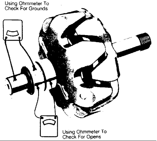
Fig. 2: Rotor Bench Test For Open or Short Circuit
Stator Test
NOTE: Delco 17SI alternator has delta stator windings and cannot
be checked for open circuit.
1) For 12SI series alternator, measure resistance between
stator leads. See Fig. 3. If reading is not infinity, replace stator.
2) On all models, connect ohmmeter leads to any stator lead
and to stator frame. Ohmmeter reading should be infinity. See Fig. 3.
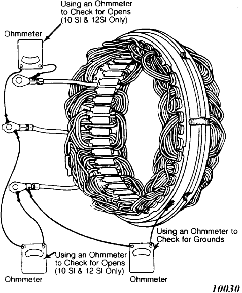
Fig. 3: Testing Stator for Open or Grounded Circuits
Diode Trio Test
1) Remove diode trio from end frame. Connect an ohmmeter to
single connector and to one of the 3 connectors. See Fig. 4. Note
reading and reverse leads. If readings are the same, replace diode
trio.
2) A good diode trio will give a high and low reading. Repeat
tests between single connector and each of the 3 connectors. Connect
ohmmeter to each of the 3 connectors. If any readings are zero,
replace diode trio.
NOTE: Before replacing diode trio, also check rectifier bridge.
DO NOT use high voltage, such as 110
testing diode trio.
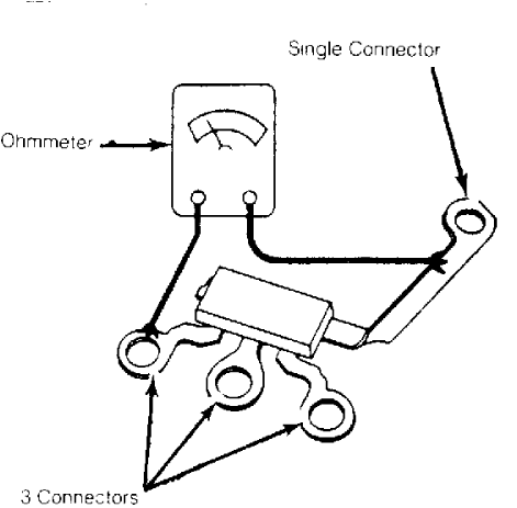
Fig. 4: Bench Testing Diode Trio
Rectifier Bridge Test
1) Position ohmmeter with one lead touching grounded heat
sink and the other lead touching flat metal on one of the 3 terminals
or threaded studs. Observe reading and reverse test lead connections.
See Fig. 5.
2) If both readings are the same, replace rectifier bridge. A
good bridge will give a high and low reading. Retest all terminals (6
tests with insulated heat sink).
3) Connect test leads to insulated heat sink and one edge of
the 3 terminals. Observe reading and reverse connections. Repeat test
on all terminals (6 tests with insulated heat sink).
4) When all 12 tests have been made, testing is complete. DO
NOT use high voltage light to check bridge. DO NOT replace diode trio
or rectifier bridge unless at least one pair of readings is the same
(with leads reversed).
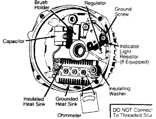
Fig. 5: Bench Testing Rectifier Bridge
2.8 ohms on 12SI series, or 2.1 ohms on 17SI series. If not, replace rotor. volt test light, whenOVERHAUL
NOTE: There are no overhaul procedures for CS130 alternators.
INSPECTION
Wash all metal parts except bearings, stator and rotor.
Inspect rotor slip rings. They may be cleaned with 400 grit or finer
polishing cloth, while rotor is being rotated. Slip rings may be lathe
turned to .002" (.05 mm) maximum indicator reading.
Slip rings are not replaceable. Excessive damage will require
rotor replacement. Inspect brushes for wear, replacing them if more
than 50% worn.
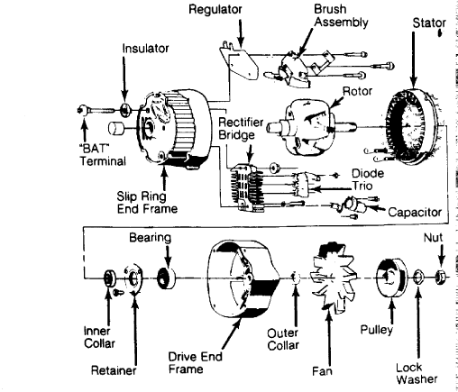
Fig. 6: Exploded View of Model 12SI Alternator
Courtesy of General Motors Corp.
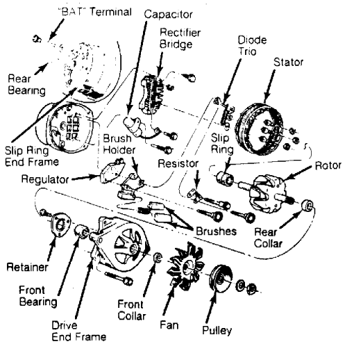
Fig. 7: Exploded View of Model 17SI Alternator
Courtesy of General Motors Corp.
SPECIFICATIONS
ALTERNATOR OUTPUT FOR CS SERIES
Stamped Rating Amps @ 14v Engine RPM
85 .................. 30 ..................... 1600
100 ................. 36 ..................... 1600
105 ................. 42 ..................... 1600
ALTERNATOR OUTPUT FOR SI SERIES
Stamped Rating Amps @ 14v Engine RPM
66 .................. 23 ..................... 1600
78 .................. 30 ..................... 1600
94 .................. 30 ..................... 1600
120 ................. 50 ..................... 1600