STARTER - BOSCH/MITSUBISHI
1988 Jeep Cherokee
1988 Starters BOSCH & MITSUBISHI
Jeep with 4.0L 6-Cyl.
DESCRIPTION
NOTE: Information on Jeep 2.5L starter not available from manufacturer.
Bosch and Mitsubishi use a permanent magnet starter. A planetary gear train transmits power between starter motor and pinion shaft. The starter magnetic field is produced by 6 permanent magnets. The Mitsubishi starter is a 12-volt unit that has the solenoid mounted on the starter housing. See Fig. 3.
TROUBLE SHOOTING
NOTE: See the TROUBLE SHOOTING - BASIC PROCEDURES article in the GENERAL TROUBLE SHOOTING section.
TESTING (ON VEHICLE)
AMPERAGE DRAW TEST
NOTE: Engine should be at operating temperature before performing this test. Heavy duty oil or a tight engine will increase starter draw amperage. Tests are performed with standard volt-ammeter tester.
Connect
tester and remote starter switch. Set voltmeter
selector to
16-volt position. Select function to 0-500-amp scale.
Connect
voltmeter leads to corresponding polarity battery terminals.
Connect
ammeter leads to corresponding battery terminals.
Disconnect coil
wire from distributor cap and attach to ground to
prevent engine
from starting.
Crank
engine and observe exact reading on voltmeter. Stop
cranking
engine. Turn tester control knob clockwise until voltmeter
reads
exactly the same as when engine was cranked with remote
starter
switch. Ammeter should indicate starter draw of about
150-220 amps.
STARTER RESISTANCE TEST
Use a voltmeter that will indicate tenths of a volt. Without disconnecting any starter connections, perform the following resistance tests:
1) Perform
following tests with engine cranking and all
terminals connected.
Connect a voltmeter at following locations:
Positive
lead to battery positive post and negative lead
to battery
terminal on starter.
Positive
lead to starter housing and negative lead to
negative post on
battery.
Positive
lead to battery negative post and negative lead
to battery cable
connector on engine block.
2) Each of these 3 connections should show a voltmeter
reading of .2 volt or less. If reading exceeds .2 volt, clean or repair cables and connections in circuit. Connect a voltmeter at following locations:
Positive
lead to battery positive post and negative lead
to cable clamp.
Positive
lead to battery negative post and negative lead
to cable clamp.
3) If
reading is other than zero on voltmeter, clean or
repair cables
and connections in circuit. Connect a voltmeter at
following
location:
* Positive
lead to battery positive post and negative lead
to starter
solenoid lead to the field coils.
4) If
reading exceeds .3 volt, clean or repair
cables and
connections in circuit.
SOLENOID TEST
Connect a
heavy jumper wire on starter relay between
battery and solenoid
terminals. If engine cranks, solenoid is okay. Go
to RELAY TEST.
If engine
does not crank, check wiring and connections
from relay to
starter. Repair or replace as necessary. If engine still
fails to
crank, starter is defective.
RELAY TEST
On
automatic transmission/transaxle vehicles, put gear
selector in
"NEUTRAL" or "PARK". On
manual transmission/transaxle
vehicles,
put gear selector in "NEUTRAL". Set parking brake and
block
wheels. DO NOT remove relay connector. Using a 12-volt test
light,
check for battery voltage
between starter relay battery terminal and
ground.
Use a
jumper wire on starter relay between battery and
ignition
terminals. If engine cranks starter relay is good. If starter
does
not crank go to next step.
Connect
another jumper wire to starter relay between
ground
terminal and ground. Repeat above test. If engine cranks,
starter
relay is good. Inspect transmission linkage for improper
adjustment
(automatic transmission), defective
neutral safety switch
(automatic transmission) or poor ground
connection between relay
housing and mounting surface.
TESTING (ON BENCH)
STARTER SOLENOID
With
starter removed, disconnect field coil wire from
field coil
terminal on starter. Using an ohmmeter, check for
continuity
between solenoid and field coil terminals.
Check for
continuity between solenoid terminal solenoid
housing. Continuity
should be present in both tests. If continuity is
present,
solenoid is good. If no continuity is present, replace
solenoid.
Reconnect field coil wire to field coil terminal.
ARMATURE FOR SHORT CIRCUIT
Place armature in a growler and hold a thin steel blade parallel 3/16" above core while rotating armature slowly. If armature
is shorted, blade will vibrate and be attracted to core. Replace shorted armature.
ARMATURE FOR GROUND
Using a self-powered test light and touch one lead to armature shaft and other lead to each commutator bar. See Fig. light glows, armature is grounded and should be replaced.
1. If
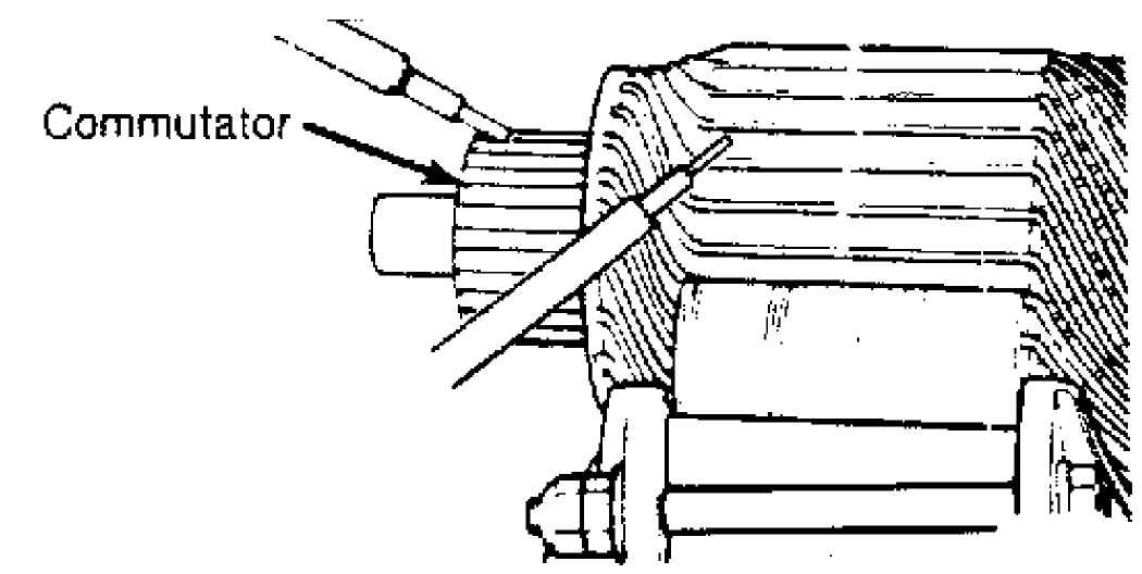
 Fig.
1: Testing Starter Armature for Ground
Fig.
1: Testing Starter Armature for Ground
FIELD COILS FOR GROUND
Using a self-powered test light and touch one probe to series field coil lead and other probe to field frame. If light glows, replace field coil housing assembly.
DRIVE CLUTCH UNIT
While holding clutch housing, rotate pinion. Drive pinion should rotate smoothly in one direction only (should not rotate in opposite direction). If drive unit does not operate properly, or if pinion is worn or burred, replace drive unit.
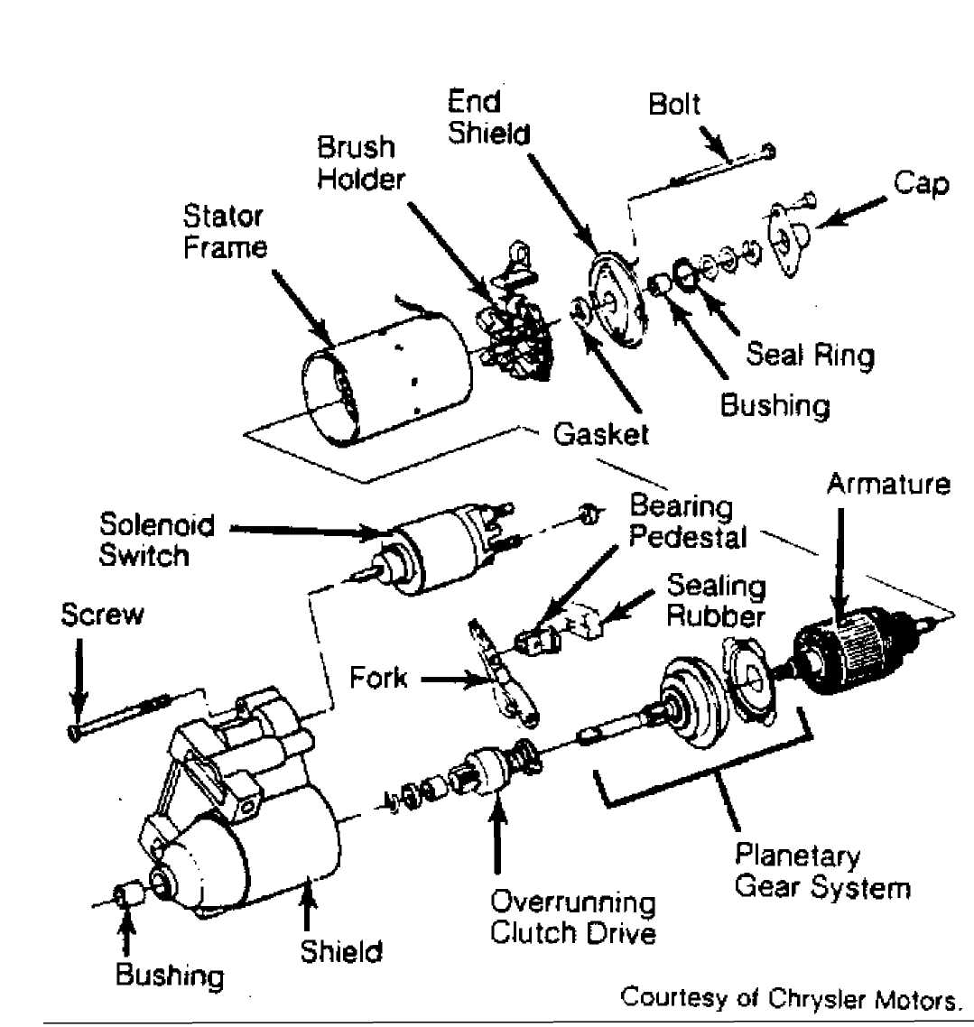
Fig. 2: Exploded View of Bosch Starter
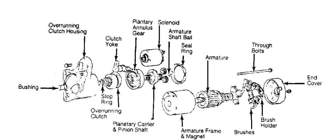
Fig.
3: Exploded View of Mitsubishi Starter
OVERHAUL
Overhaul information not available.
SPECIFICATIONS
BOSCH & MITSUBISHI STARTER SPECIFICATIONS Application (1)
Specification
 Cranking
Amperage Draw 120-220
Amps
Cranking
Amperage Draw 120-220
Amps
No Load Test Voltage 11-11.5 Volts
No Load Test Amperage Draw 75-85 Amps
No Load Test Minimum RPM 2500-3625
Solenoid Closing Voltage (All) 7.3-7.8 Volts
(1) - New brushes are 11/16" (17.5 mm) long.