SPARK CONTROL SYSTEM
1988 Jeep Cherokee
1988 Exhaust Emission Systems JEEP SPARK CONTROL SYSTEMS
DESCRIPTION
Jeep vehicles use spark control devices to assist ignition system in controlling exhaust emissions. They are Spark Control Temperature Override (CTO) valve, Non-Linear Vacuum Regulator (NLVR) valve, Forward Delay Valve, Reverse Delay Valve and on 4-cylinder engines, Vacuum Spark Control Delay Valve. System application depends upon engine size, emissions category and vehicle model.
COOLANT TEMPERATURE SENSOR (CTS)
The coolant temperature sensor is located in the intake manifold coolant jacket. This sensor provides a voltage signal to the Electronic Control Unit (ECU). The ECU uses this signal to determine engine temperature. During cold engine operation, the ECU responds by increasing ignition advance and inhibiting EGR operation.
NON-LINEAR VACUUM REGULATOR VALVE (NLVR)
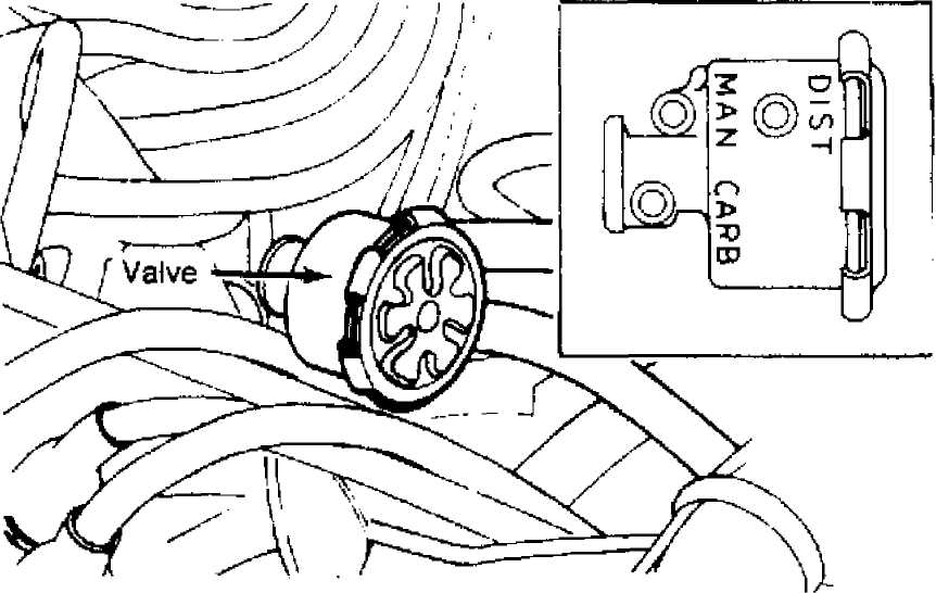
Fig. 1: Non-Linear Vacuum Regulator Valve Courtesy of Chrysler Motors.
OPERATION
NLVR valve is used on carbureted 6.0L models. This valve supplies vacuum advance unit with a regulated combination of manifold and carburetor ported vacuum when engine load is low and switches to supply only carburetor ported vacuum as load increases.
NON-LINEAR VACUUM REGULATOR VALVE
There are 2 input ports on NLVR: intake manifold vacuum and carburetor ported vacuum. One outlet port connects to distributor vacuum unit. At curb idle, regulated vacuum is supplied to advance unit, when manifold vacuum is high and ported vacuum is very low. See Fig. 1.
NLVR regulates vacuum signal so it is between these 2 vacuum source levels at idle. As engine load increases and vacuum signal is above 7.5 in. Hg vacuum, regulator valve switches to ported vacuum output.
FORWARD DELAY VALVE
Some engines use this valve to improve driveability and reduce hydrocarbon emissions. Valve functions to delay effects of sudden increases in vacuum. This prevents sudden spark advance during deceleration.
REVERSE DELAY VALVE
Some engines use this valve to improve cold driveability and reduce hydrocarbon emissions. Valve is installed in vacuum line to delay effects of manifold vacuum decrease causing retarded ignition timing.
VACUUM ADVANCE COOLANT TEMPERATURE OVERRIDE (VA-CTO)
This valve is used on carbureted 6.0L engines to improve driveability when engine is cold. It is located in vacuum advance circuit. When vacuum is greater at port "4" than at port "1", air must flow through orifice to equalize pressure. This creates momentary delay that prevents sudden decrease in spark advance. When vacuum is greater at port "1" than at port "4", air flows freely through check valve and pressure is instantly equalized.
TESTING
NON-LINEAR VACUUM REGULATOR VALVE (NLVR)
Connect vacuum gauge to distributor port "DIST" on NLVR. With engine at idle speed, a vacuum reading of 7 in. Hg vacuum should be shown. As throttle is opened and engine speed increases, ported vacuum level should be indicated. If not, replace NLVR. See Fig. 1.
FORWARD DELAY VALVE
Connect
external vacuum source to port on Black (or Red)
side of delay
valve. Connect vacuum gauge to port on colored side of
valve.
Apply
a constant 10 in. Hg vacuum. Note time
required for
gauge pointer to move from 0-8 in.
Hg.
If valve
fails to meet time limits, replace valve. If
valve meets
specifications, install so that Black (or Red) side is
toward
vacuum source.
FORWARD DELAY VALVE TIME LIMITS (1)
 Valve
Color Min. Time Max Time
Valve
Color Min. Time Max Time
Black/Purple 3.2
Black/Gray 8
Black/Brown 16
Black/Orange 1.5
Black/White 50
Black/Yellow 80
Black/Green 160
(1) - Time in seconds.
4.8 12 24
2.5 77
120
240
REVERSE
DELAY VALVE
Connect
external vacuum source to port on White side of
delay valve.
Connect vacuum gauge to port on colored (non-White) side
of
valve.
Apply
a constant 10 in. Hg vacuum, note time
required for
gauge pointer to move from 0-8 in.
Hg.
If
valve fails to meet time limits, replace valve. If
valve meets
specifications, install with non-White side toward vacuum
source.
REVERSE DELAY VALVE TIME LIMITS
(1)
Valve
Color
Min. Time
Max. Time
4.8
12
18
24
120
450
White/Purple 3.2
White/Gray 8
White/Gold 12
White/Brown 16
White/Yellow 80
White/Red 300
White/Orange 1.5 2.5
(1) - Time in seconds.
VACUUM
SPARK CONTROL DELAY VALVE
Connect
"T" fitting at ports "1" and
"4". Connect vacuum
gauge to
each fitting. Start engine. Vacuum should be equal at both
ports.
See Fig. 2.
When
throttle is suddenly depressed, vacuum at port "1"
will
instantly decrease and vacuum at port "4" should
be maintained
momentarily. If valve fails these tests, replace
valve.

Fig.
2: Vacuum Spark Control Delay Valve
Courtesy of Chrysler Motors.