STEERING GEAR - POWER
1988 Jeep Cherokee
1987-88 STEERING
Jeep Power Steering Gears - Saginaw Rotary Valve
Cherokee, Comanche, Grand Wagoneer, Pickup, Wagoneer, Wrangler
DESCRIPTION
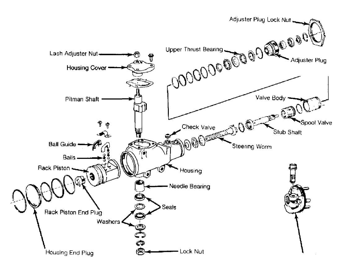
Steering gear is a recirculating ball-type, available in either a constant or a variable ratio design. Steel balls form a "rolling thread" between steering gear worm shaft and rack/piston nut. Worm shaft thrust is absorbed by a thrust bearing and two races at lower end, and by a bearing in adjuster plug at upper end.
This design puts spring pressure on worm shaft to ensure proper thrust bearing preload. Adjuster plug provides initial preload adjustment and service adjustment (when repairing gear). As worm shaft is turned right, rack/piston is moved upward in gear.
As worm shaft is turned left, rack/piston is moved downward in gear. The rack/piston teeth mesh with sector, which is forged as part of sector shaft. Rotating worm shaft moves sector shaft, which turns wheels through mechanical linkage. See Fig. 1.
TROUBLE SHOOTING
Refer to TROUBLE SHOOTING - BASIC PROCEDURES article in the GENERAL TROUBLE SHOOTING section.
LUBRICATION
See POWER STEERING GENERAL SERVICING article.
TESTING
See POWER STEERING GENERAL SERVICING article.
Steering Shaft
30538
Fig. 1: Exploded View of Saginaw Rotary Valve Power Steering Gear
ADJUSTMENTS
THRUST BEARING PRELOAD ADJUSTMENT
Remove
steering gear from vehicle. Remove adjuster plug
lock nut. Turn
adjuster plug clockwise with a spanner wrench until
plug
is seated in housing. This will require 20-30 ft.
lbs. (27-41 N.
m) of torque.
Place
an index mark on housing opposite one spanner wrench
hole in
adjuster plug. Measure 1/2" (13 mm)
counterclockwise from mark
and again
mark housing. Rotate plug counterclockwise until hole in
adjuster
lines up with second mark.
Tighten
lock nut. Ensure adjuster remains in position.
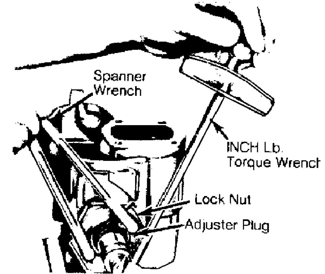
Attach an INCH
lb. torque wrench to end of input shaft. Turn input
shaft to
right stop, then back 1/4 turn.
Using
torque wrench measure rotational torque required to
turn
shaft. Reading should be taken with beam of torque wrench
near
vertical while turning it counterclockwise at an even rate.
Torque
reading should be 4-10 INCH
lbs. (.4-1.1 N.m). See. Fig. 2.
NOTE: If reading does not fall within this range, adjuster plug
may have turned while lock nut was being tightened. Steering gear may be incorrectly assembled or worm shaft thrust bearings and races may be defective. Repair as required and readjust preload.
30539
Fig. 2: Measuring Thrust Bearing Preload
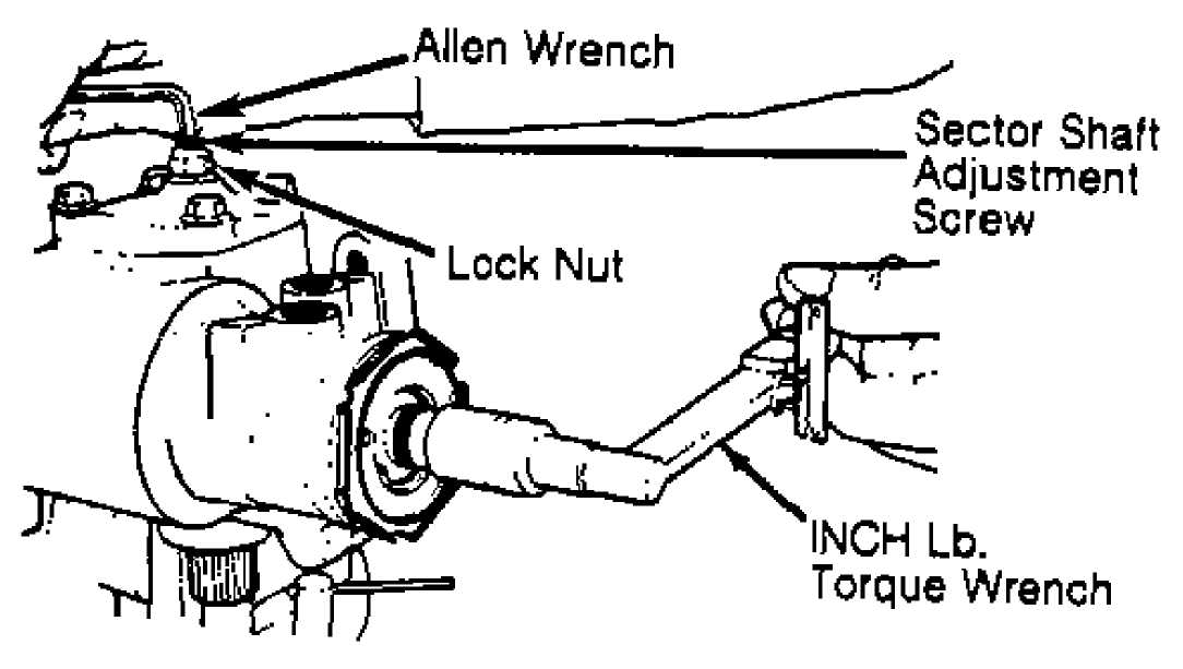
OVER-CENTER PRELOAD TORQUE ADJUSTMENT
Loosen
adjuster screw lock nut. Back off adjuster screw
until
stopped, then turn in 1 full turn. Rotate
input shaft from stop
to stop counting
number of turns. Turn shaft half way back to center
position.
Attach an INCH lb. torque wrench to input shaft. Turn
shaft from side to side through specified arc on each side of center. See OVER-CENTER PRELOAD chart. Note torque reading going over center. Adjust thrust bearing preload before over-center preload. See Fig. 3.
OVER-CENTER PRELOAD SPECIFICATIONS - INCH LBS. (N.m)
 Application
New Gears .. . Used Gears (2)
Arc
45. 45.
Over-Center
4-8 (.4-.9) 4-5 (.5-.6)
(1) Total
14 (1.5) 14 (1.5)
- Total preload is sum of thrust bearing and over-center preload.
- In service for more than 400 miles (640 km.).
30540
Fig. 3: Adjusting Over-Center Preload
REMOVAL & INSTALLATION
POWER STEERING PUMP
Removal & Installation
Loosen
and remove pump drive belt. Disconnect pressure and
return
hoses from pump. Cap ends to prevent loss of fluid
or
contamination.
Remove
bracket-to-engine bolts. Remove pump and mounting
bracket as an
assembly. To install, reverse removal procedure. Fill
and bleed
system.

Fig. 4: Power Steering Pump (Cherokee & Commanche)
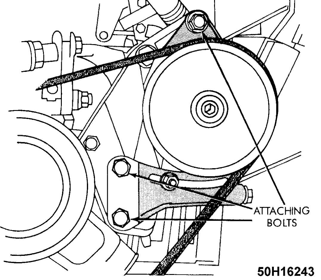
Fig. 5: Front Bracket Boltsp (Cherokee & Commanche)
STEERING GEAR
Removal
Remove
collapsible steering column. Raise and support
vehicle. Place
drain pan under steering gear assembly. Center steering
gear.
Disconnect hydraulic hoses from gear and cap ends.
Disconnect
steering linkage from pitman arm. Remove pitman arm
from gear.
Remove
flexible coupling clamp bolt and bolts retaining
steering gear to
frame. Disconnect gear from flexible coupling and
remove gear
from vehicle. On Jeep CJ7 and Scrambler models, remove
steering
gear and mounting bracket as an assembly.
Installation
To install, reverse removal procedure. Fill pump reservoir. Bleed air from system. See POWER STEERING GENERAL SERVICING article.
OVERHAUL
SUBMERGED VANE POWER STEERING PUMP
Disassembly
1) Drain pump reservoir. Clean exterior of unit. Measure distance shaft protrudes from pulley, and record for assembly reference. Using pulley remover, remove pulley from shaft. Clamp pump in vise; DO NOT overtighten vise. Remove pressure line union, reservoir mounting stud and reservoir. See Fig. 6. Remove and discard pressure line union "O" rings.
 "O"
Ring
"O"
Ring
Cap/Dtpstick
Reservoir
End Plate
Pressure Plate Spring
Pressure Pfate
Pump Ring
8 Retaining Ring 9. Vane
Rotor
Thrust Plate
Dowel Pin
Drive Shaft
"O"
Ring
15- "Î" Ring
"O" Ring
Plug
Plug
Housing
20 Drive Shaft Seal
Bushing
Plug
23. "O" Ring 24 "O" Ring
Dowel Pin
Flow Conirol Valve
Spfing
"O" Ring
End Plate Retaining Ring
Reservoir Mounting Stud
Pressure Line Union
 Fig.
6: Exploded
View of Pump Assembly (Grand Wagoneer &
Wrangler) Courtesy
of Chrysler Motors
Fig.
6: Exploded
View of Pump Assembly (Grand Wagoneer &
Wrangler) Courtesy
of Chrysler Motors
Using
punch and screwdriver, remove end plate retaining
ring. Remove
end plate and pressure plate spring. Remove "O"
ring,
flow control valve and spring. Note direction of pump
ring
installation for reassembly reference.
Using
soft-faced hammer, tap end of drive shaft to loosen
pressure
plate. Remove pressure plate, pump ring, vanes, retaining
ring,
rotor and thrust plate assembly from body. Remove drive
shaft.
Using a screwdriver, pry drive shaft oil seal from
housing. Remove
dowel pins and seals.
Cleaning & Inspection
1) Clean all pump components in solvent, and blow dry.
Inspect flow control valve assembly for wear, scoring, burrs and other damage. Inspect seal bore for burrs, nicks and score marks.
Inspect
machined surfaces of body for scratches and burrs.
Check
"O" ring mating surfaces.
Inspect drive shaft for excessive
wear.
Inspect
pump ring for roughness. Check thrust plate and
pressure
plate for scoring and wear. Ensure vanes slide freely but
fit
snugly into slots. If vanes are
loose in slots, replace rotor and/or
vanes.
Reassembly
1) Before installation, coat all "O" rings, rotor, pressure
plate and end plate with petroleum jelly. Install new drive shaft seal in housing. Install "O" ring in third groove of housing. Install dowel pins in thrust plate. Install drive shaft through thrust plate and rotor. Install NEW retaining ring. Ensure rotor slides freely on drive shaft splines.
Install
drive shaft in pump housing. Ensure thrust plate
engages with
dowel pins. Install pump ring on dowel pins with rotation
arrow
facing upward. Install vanes with rounded edges toward pump
ring.
Lubricate
outer chamfered edge of pressure plate with
petroleum
jelly. Install pressure plate with spring groove facing
upward.
To seat pressure plate, place large socket on pressure plate
and
press downward approximately 1/16".
Install
end plate "O" ring in second
groove of housing.
Install pressure
plate spring and end plate in housing. Press end
plate downward,
and install retaining ring. Install "O" ring,
flow
control valve and spring.
Install
mounting stud and pressure line union "O" rings
in
rear of pump housing. Lubricate inner edge of reservoir with
petroleum
jelly, and install. Install
mounting stud. Tighten stud to
specification. Install pressure
line union, and tighten to
specification. See appropriate table
under TORQUE SPECIFICATIONS.
Using
Pump Pulley Installer (J-25033-B), install
pulley on
pump shaft. Ensure shaft
protrudes distance measured in disassembly
procedure.
When
replacing plastic pulley with metal pulley, install
pulley flush
with end of shaft. Install pump on engine, and compare
alignment
with adjacent pulleys. If necessary, correct alignment by
using
pump pulley installer to adjust shaft protrusion.
NON-SUBMERGED VANE POWER STEERING PUMP
Disassembly
Remove
return tube. Clean exterior of unit. Measure
distance
shaft protrudes through pulley, and record for reassembly
reference.
Using pulley remover, remove pulley from shaft. Remove
fitting,
"O" ring, flow control valve and
spring. See Fig. 7.
Remove
snap ring, drive shaft and bearing. Note direction
of snap ring
installation for reassembly reference. Support drive
shaft
bearing on inner race, and press drive shaft from bearing.
Using
screwdriver, remove drive shaft seal from housing.
Insert
punch into access hole to disengage and remove
retaining
ring. Using a brass drift, tap on thrust plate, and remove.
Remove
"O" ring, pump ring, rotor and
vanes. Remove dowel pins,
pressure plate, "O"
ring and pressure plate spring. Remove "O"
ring,
dowel pin and
sleeve.
 9.
Pump Housing
9.
Pump Housing
Return Tube
Dowel Pin
Sleeve
"O- Ring
Pressure
Plate Spring
15.-Î’Ring
1 Snap Ring
Drive Shaft Bearing
Drive Shaft
Drive Shaft Seal
Fitting
"0n Ring
Flow Control Valve
Pressure Plate
Dowel Pins
Vanes
Rotor
Pump Ring
-Î" Ring
Thrust Plate
8, Flow Control Valve Spring 23. Retaining Ring
 Fig.
7: Exploded
View of Cherokee & Comanche
Pump Assembly Courtesy of Chrysler Motors
Fig.
7: Exploded
View of Cherokee & Comanche
Pump Assembly Courtesy of Chrysler Motors
Cleaning & Inspection
1) Clean all pump components in solvent, and blow dry.
Inspect flow control valve assembly for wear, scoring, burrs and other damage. Inspect seal bore for burrs, nicks and score marks.
Inspect
machined surfaces of body for scratches and burrs.
Check
"O" ring mating surfaces.
Inspect drive shaft and sleeve for
wear.
Inspect
pump ring for roughness. Check thrust plate and
pressure
plate for scoring and wear. Ensure vanes slide freely but fit
snugly
into slots. If vanes are loose in slots, replace rotor and/or
vanes.
Reassembly
Lubricate
all "O" rings, seals, pump ring,
rotor and vanes
with petroleum jelly.
Install sleeve. Ensure sleeve is fully seated.
Install
"O" ring in sleeve seat. Install
small dowel pin
in pump housing. Install pressure plate spring
and "O" ring. Install
pressure
plate with dowel pin hole aligned with dowel pin holes.
Install
dowel pins.
Install pump ring with identification marks located
adjacent to one dowel pin. Install rotor with counterbore toward drive shaft end of housing.
4) Install
vanes with rounded edges toward pump ring. Install
thrust
plate "O" ring. Install thrust
plate with indentations aligned
with bolt holes of housing.
Install retaining ring.
CAUTION: Pump ring must be installed with identification marks located adjacent to dowel pins. Thrust plate must be installed so indentations in thrust plate align with bolt holes of housing and thrust plate engages with pump ring dowel pins.
Using a
socket, install drive shaft seal in housing until
seal bottoms.
Support drive shaft bearing on inner race, and press
drive shaft
into bearing. Install drive shaft and bearing in pump
housing.
Rotate
drive shaft during installation to align with rotor
serrations.
Ensure bearing is fully seated in pump housing. Snap ring
should
be installed with large lug area (near snap ring pliers
hole)
positioned right of small lug
(near snap ring pliers hole), ensuring
beveled
area of snap ring is properly positioned.
Install
spring, flow control valve and "O" rings.
Install
return tube with new "O" ring.
Install pulley.
STEERING GEAR
Disassembly
Cap all
openings in gear. Clean gear exterior thoroughly.
Mount gear in
vise so that pitman shaft points downward. Rotate
housing end
plug retainer ring until one end of plug is over the hole
in the
housing.
Force
end of ring from groove in housing and remove.
Rotate
input shaft counterclockwise to force housing end plug out
of
housing. Rotate input shaft
clockwise 1/2 turn to draw
rack/piston
inward. Remove piston end
plug.
CAUTION: DO NOT rotate shaft more than is necessary to remove plug as ball bearings will fall out of worm and rack piston assembly.
3) Remove
lock nut from sector shaft adjuster. Remove sector
shaft cover.
Remove and discard "O" ring from
cover. Turn input shaft
until sector
shaft teeth are centered in housing.
Tap end of
sector shaft with a soft-faced hammer to free
shaft from housing,
then remove sector shaft. Remove adjuster plug
lock nut. Remove
adjuster plug with a spanner wrench.
Insert a
rack/piston arbor into end of rack/piston until
arbor just
contacts worm shaft. Turn stub shaft counterclockwise to
force
rack/piston onto arbor. Remove rack/piston and arbor as an
assembly.
Take care
to keep arbor fully inserted so ball bearings
will not fall out.
Remove input shaft and control valve assembly from
housing.
Remove worm, wormshaft lower thrust bearing, and races from
housing.
Reassembly
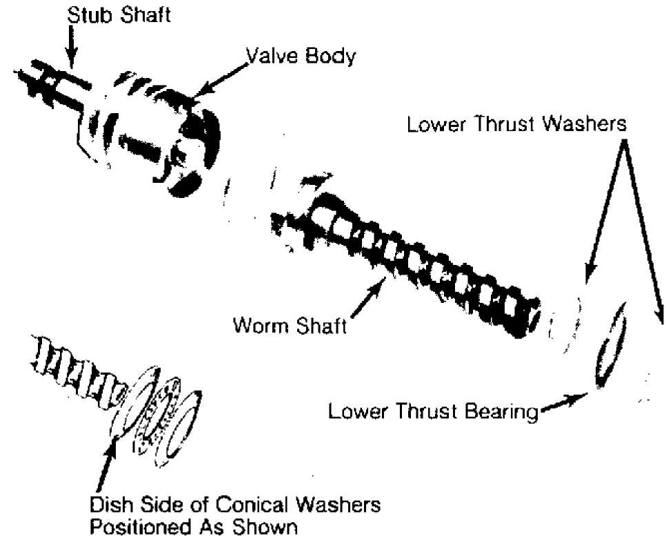
1) Lubricate all parts with clean power steering fluid before reassembly. Install the lower thrust bearing and races onto the worm. Cupped side of thrust washers must face toward stub shaft. See Fig. 8.
30541
Fig. 8: Reassembly of Valve Body & Worm Shaft Assembly
NOTE: If conical thrust races are used, ensure tapered surfaces
are parallel to each other and that cupped sides face toward stub shaft.
Install
stub shaft cap "O" ring in valve
body. Align valve
body drive pin on
worm with narrow pin slot in valve body. Worm drive
lugs
must engage in stub shaft cap.
Install
valve body and worm assembly into housing. Perform
installation
by pressing directly on valve body only. This will
prevent stub
shaft "O" ring from disengaging
from valve body.
Valve
body is correctly seated when fluid return port in
housing
is fully visible. Ensure worm locating pin is fully engaged in
valve
body. Place seal protector over input shaft, install a new
adjuster
plug "O" ring, then install
adjuster plug.
Remove
seal protector from housing and loosely install
adjuster plug
lock nut. Insert arbor and rack/piston into housing.
Align worm
and rack/piston and turn stub shaft clockwise to engage
worm.
Maintain pressure on arbor until worm is fully engaged.
Turn input
shaft clockwise until middle rack groove in
rack/piston is
aligned with center of sector shaft roller bearing.
Remove arbor.
Install a new sector shaft cover gasket.
Thread
sector shaft cover onto adjuster screw until
bottomed.
Back off 1 1/2 turns. Install sector shaft
so that center
gear tooth meshes with
center groove in rack/piston. Install cover
attaching
bolts.
Install
adjuster lock nut halfway onto sector shaft.
Install piston and
plug in rack/piston. Install housing end plug "O"
ring,
end plug and retainer ring. Adjust worm bearing preload
and
over-center preload at this time.
ADJUSTER PLUG
Disassembly
Remove
thrust bearing retainer ring with a screwdriver,
taking care not
to score needle bearing bore. Discard retainer ring.
Remove
thrust bearing spacer, thrust bearing and bearing races.
Remove
and discard adjuster plug "O" ring,
then remove
input shaft seal retainer. Remove and discard dust
seal. Pry input
shaft seal from adjuster plug.
Inspect
needle bearing in adjuster plug. If necessary,
remove
bearing by pressing out from spacer end. See Fig. 9.
Inspection
Inspect thrust bearing for cracks and rollers for pitting, scoring, or cracking. Check thrust races and spacer for damage or damage. Replace parts as necessary.
 Dust
Seal
Dust
Seal
Needle Bearing
"0" Ring ň
Thrust Bearing i
Spacer
Retainer 30542
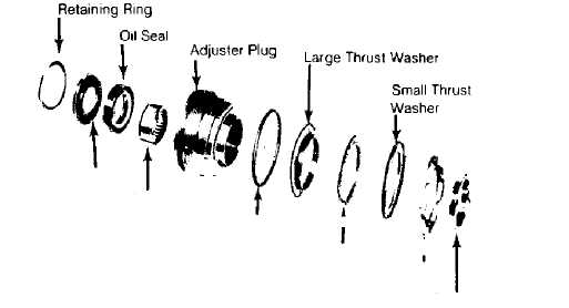
Fig. 9: Exploded View of Adjuster Plug Assembly
Reassembly
1) Press roller bearing into adjuster plug (identification end facing arbor) until bearing bottoms on input shaft seal bore.
Install input shaft seal with spring in seal facing adjuster plug.
Install
dust seal into adjuster plug. Rubber face of seal
must face away
from plug. Install retainer ring. Install adjuster plug
"O"
ring.
Assemble
thrust bearing, thrust bearing race, and thrust
bearing spacer on
adjuster plug. Using a brass or wooden dowel, press
bearing
retainer into needle bearing bore.
RACK/PISTON & WORM
Disassembly
Remove worm, lower thrust bearing and bearing races from rack piston. Remove piston ring and back-up "O" ring from rack/piston. Remove ball return guide clamp, ball return guide and all ball bearings from rack/piston.
Inspection
Clean and
dry all parts. Inspect worm and rack/piston
grooves for scoring.
Inspect ball bearings for damage. If any ball
bearings are
damaged, replace entire set. Check ball guides for
pinching of
ends.
Inspect
lower thrust bearing races for cracking, scoring,
or pitting.
Replace wormshaft and rack/piston as an assembly if either
part
is damaged. Inspect rack/piston teeth for chips, cracks, dents
or
scoring.
Reassembly
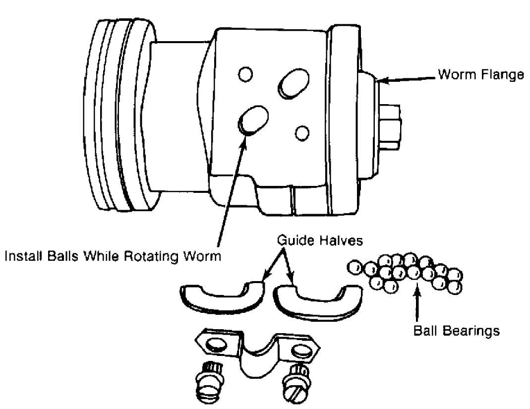
1) Install
"O" ring and piston ring onto
rack/piston using
care not to twist them. Install worm into
rack/piston until worm is
against piston
shoulder. Install ball bearings into rack/piston while
slowly
rotating worm counterclockwise.
NOTE: See RACK PISTON & WORM ASSEMBLY BALL BEARINGS table for
number of balls to be installed. BE SURE to install light and dark colored balls alternately, as Black balls are .0005" smaller than Silver balls.
Install
correct number of balls in ball guide. Bearings in
guide must be
in sequence with bearings in rack/piston. Hold balls in
place
with chassis lubricant and install return ball guide assembly
into
position.
Install
clamp and tighten attaching bolts. Alternate light
and
dark colored balls when installing. See Fig. 10.
Insert
rack/piston
arbor into rack/piston until it contacts worm. Maintain
pressure
on arbor, and back worm out of rack/piston. DO NOT allow
ball
bearings to drop out of circuits.
RACK PISTON & WORM ASSEMBLY BALL BEARINGS TABLE
 Application Rack/Piston Guide
Jeep 18 6
30543
Fig. 10: Installing Ball Bearing into Rack/Piston Assembly
ROTARY VALVE
NOTE: Complete valve assembly is balanced during assembly. If replacement of any part other than rings or seals is necessary, replace complete assembly.
Disassembly
1) Remove and discard stub shaft cap "O" ring. Invert valve and lightly tap end of stub shaft against wood block until shaft cap is free of valve body. Pull stub shaft outward until drive pin hole is visible. Depress the pin to remove the stub shaft from the valve body. See Fig. 11.
NOTE: DO NOT pull shaft any further than 1/4" (6 mm) or spool valve may become cocked in valve body.
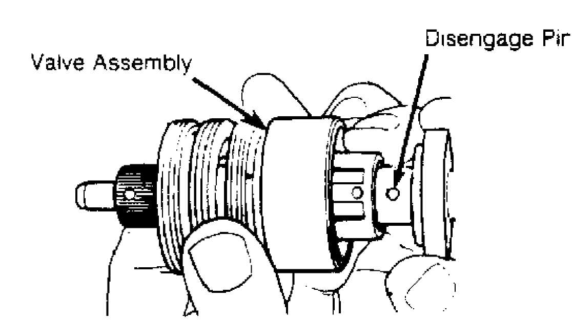
30335
Fig. 11: Pulling Shaft from Valve Assembly
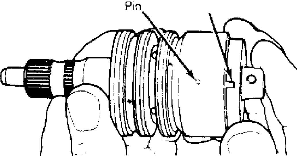
2) Disengage
drive pin and carefully remove stub shaft from
valve
body and spool assembly with a twisting motion. If binding
occurs,
realign valve and try removal again.
CAUTION: DO NOT force stub shaft or spool out of valve body.
3) Remove
spool valve from valve body with twisting motion.
Remove
and discard all "O" rings and
Teflon rings.
 Spool
Valve ""’ "/J- °
R’nQ
Spool
Valve ""’ "/J- °
R’nQ
"0" Rings (3)
Stub Shaft
30334
Fig. 12: Exploded View of Valve Body Assembly
Reassembly
1) Lubricate all valve body components with power steering fluid. Install replacement back-up "O" rings in seal grooves and
install replacement seal rings over back-up rings. Take care not to damage seal rings during installation.
NOTE: Teflon seal rings may appear to be distorted after
installation. However, heat of operation will straighten them.
Lubricate
replacement spool valve damper "O" ring
with
petroleum jelly. Install on spool
valve. Carefully insert spool valve
into
valve body.
Push spool
valve through valve body until locating pin
hole is visible at
opposite end of valve body and spool valve is flush
with the
notched end of the valve. Install stub shaft in spool valve
and
valve body.
Be
sure stub shaft locating pin is aligned with spool
valve
locating hole. Align notch in stub shaft cap with stub
shaft
locating pin and press sub shaft
and spool valve into valve body.
Install stub shaft cap "O"
ring into valve body. See Fig. 13.
CAUTION: Before installing assembled valve body into gear housing, be sure valve body stub shaft locating pin is fully engaged in stub shaft cap notch. DO NOT allow stub shaft to disengage from valve body pin.
Notch
3Q336
Fig. 13: Aligning Pin & Notch for Input (Stub) Shaft
Stub shaft locating pin must align with spool valve locating hole.
STEERING GEAR HOUSING
Disassembly
Remove
sector shaft seal retaining ring and remove lower
steel washer.
Remove lower seal, spacer washer and upper seal from
housing.
Press sector shaft bearing out of housing from lower end.
To remove hose connector seat, tap out seat using a 5/16"-
18 thread tap. Thread connector seats ONLY 2-3 threads. Install a bolt with a flat washer and nut into seat.
3) Hold bolt from turning and tighten nut to extract seat from housing. Some steering gear units have metric thread fittings and hose fittings which use "O" ring seals instead of connector seats. Remove check valve and spring from inlet port and discard.
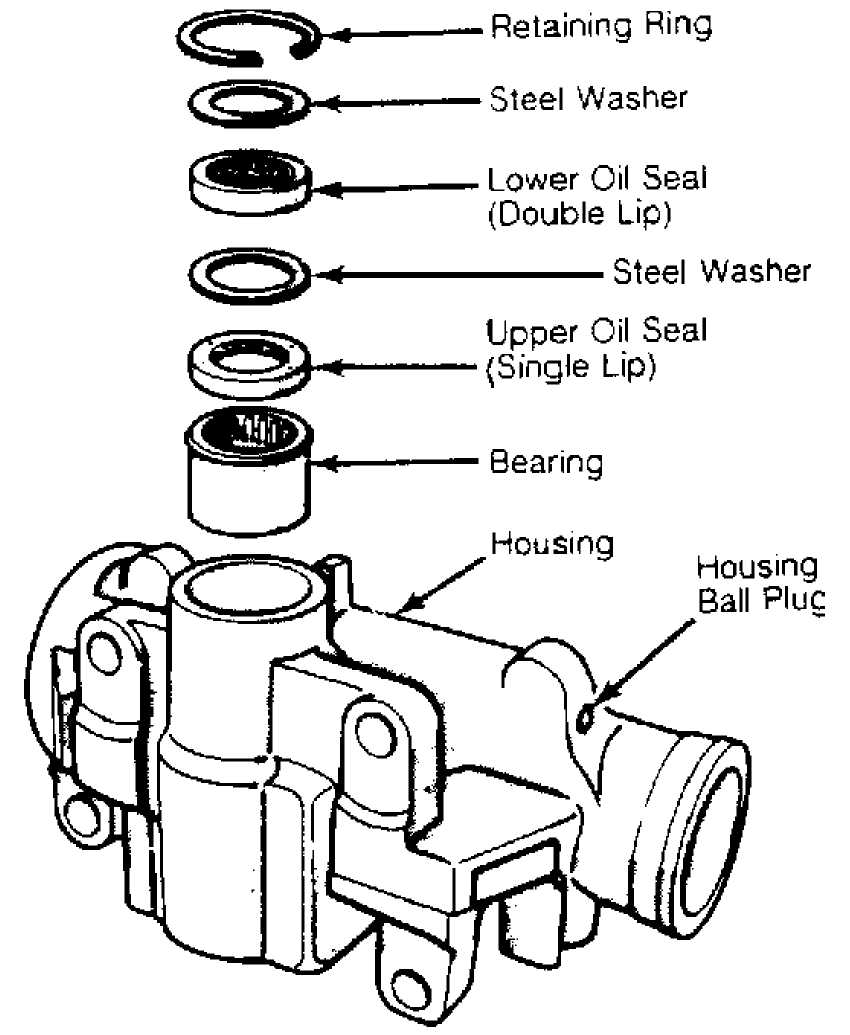
30337
Fig. 14: Gear Housing Seals & Bearing
Inspection
1) Replace housing if bore is severely worn, scored or pitted. Minor scratches may be removed with crocus cloth. Inspect
housing ball plug for fluid leakage. Seat ball plug with blunt punch.
Spray
ball area with Loctite Solvent 7559 and
dry with
compressed air. Cover ball
area with Loctite Sealant 290. Allow
sealant
to cure for 2 hours before assembling
gear.
Inspect
all retaining ring, bearing and seal surfaces in
housing. Replace
housing if any surface is worn or damaged.
Reassembly
Working
from upper end, press a new bearing into housing
until it is
seated .030" (.76 mm) below shoulder
in housing bore.
Lubricate new seal with power steering fluid.
Install
single lipped seal and spacer washer only far
enough to provide
clearance for next seal, washer and retaining ring.
DO NOT bottom
seal against housing counterbore.
Install
double lipped seal and steel washer. Install
retaining ring. DO
NOT allow seals to contact one another. To ensure
proper seal
action, be sure there is clearance between them.
If port
seat was removed, position new spring, check
valve, and a new
seat over opening in housing. Drive into place using
a brass
drift.
TORQUE SPECIFICATIONS
CHEROKEE, COMANCHE, WAGONEER & WRANGLER
TORQUE SPECIFICATIONS
(CHEROKEE, COMANCHE, WAGONEER & WRANGLER)
Application Ft.
Lbs. (N.m)
Adjuster Plug Lock Nut 80 (108)
Gear Housing-to-Frame Attaching Bolts 75 (102)
Pitman Arm Attaching Nut 185 (250)
Rack Piston End Plug 50 (68)
Sector Shaft Adjuster Lock Nut 33 (45)
Side Cover Bolts 45 (60)
GRAND WAGONEER & "J" TRUCK)
TORQUE SPECIFICATIONS (GRAND
WAGONEER & "J"
TRUCK)
Application Ft.
Lbs. (N.m)
Adjuster Plug Lock Nut 85 (116)
Gear Housing-to-Frame Attaching Bolts (95)
Pitman Arm Attaching Nut 185 (250)
Rack Piston End Plug 75 (102)
Sector Shaft Adjuster Lock Nut 33 (45)
Side Cover Bolts 40 (54)