A/C-HEATER SYSTEM -MANUAL
1988 Jeep Cherokee
1988 Manual A/C-Heater Systems
JEEP
* PLEASE READ THIS FIRST *
CAUTION: When discharging air conditioning system, use only approved
árefrigerant recovery/recycling equipment. Make every attempt
áto avoid discharging refrigerant into the atmosphere.
DESCRIPTION
áOn Cherokee, Comanche and Wagoneer, the Climate Control
System is an integral assembly combining air conditioning, heating and
ventilating capabilities for models with air conditioning. The A/
C
registers are built into instrument panel.
áOn Wrangler models, a dual flow unit with the capability of
recirculating air or drawing air from outside is used. It incorporates
under-dash registers and uses a blend-air type system.
áThe A/C components include a compressor, condenser, receiver
drier, a sight glass (in the receiver-to-evaporator line) and
evaporator housing. Evaporator housing contains evaporator core,
expansion valve, thermostat, wiring and drain tube. Blower motor and
fan are located in blower housing, which is attached to evaporator
housing.
áVents provided in evaporator housing are adjustable to direct
air to different positions in vehicle's interior. System controls
include fan and temperature control knobs built into lower evaporator
housing assembly or temperature and mode levers on control panel
integrated with instrument panel.
OPERATION
A/C SYSTEM CONTROLS
áTemperature & Fan Control Knobs
á(Wrangler)
áThe right rotary control knob allows selection of desired
temperature. Knob has "OFF" "1", "2" and "3" positions for different
levels of cooling. The left rotary fan switch (knob) controls blower
motor speed. Knob has "OFF", "LOW", "MED" and "HI" positions. Fan will
operate unless mode control lever is in "OFF" position.
áThe A/C fan switch is a 3-speed unit used in conjunction with
a blower motor resistor. Fan switch controls low, medium and high
speed operation. Switch may be serviced by removing access plate
located on lower evaporator core housing, below control panel.
áThe A/C temperature control switch has a thermostat unit
built-in. Cooling adjustment is done by turning knob in a clockwise
rotation. For fast, efficient system operation in hot weather, vehicle
should be purged of hot air by driving about 2-3 city blocks with at
least one window open. During this time, temperature control knob
should be rotated clockwise to "MAX" position and fan control knob
placed in "HI" position. This allows evaporator to pre-cool and avoid
typical first blast of warm air.
áTemperature Control Panel
á(Cherokee, Comanche & Wagoneer)
áThe upper temperature control (mode) lever includes "MAX"
,
"NORM", "BI-LEVEL", "VENT", "HEAT" and "OFF" positions. At the far end
of the scale, a symbol for defroster indicates defrost position. In
"BI-LEVEL" position, a mixture of floor heat and defroster air is
obtained.
áThe lower temperature control lever operates blend-air door
in heater core housing. At full right position, all air is directed
through heater core, providing maximum heat flow. At full left
position, all air is directed around heater core providing fresh air.
Control can be set in any intermediate position to provide a blend of
heated and unheated air. Heater must be in heat or defrost mode before
any air can enter vehicle.
TROUBLE SHOOTING
áSee JEEP TROUBLE SHOOTING at the end of this article.
REMOVAL & INSTALLATION
CONDENSER
áRemoval (Cherokee, Comanche & Wagoneer) NOTE: On these
models, condenser and receiver-drier are replaced
áas a unit.
á1) Drain radiator. Disconnect fan shroud and radiator hoses.
Disconnect automatic transmission cooler lines (if equipped)
.
Discharge A/C system using approved refrigerant recovery/recycling
equipment.
á2) Disconnect A/C hoses from condenser. Unplug low pressure
switch. Remove radiator and condenser as an assembly. Detach condenser
retaining bolts. Separate condenser from radiator. Remove receiver
drier from condenser.
NOTE:
Plug receiver-drier openings whenever unit is removed from
ácondenser. Add 1 oz. of refrigerant oil (AMC No. 8132400) to
ásystem when replacing condenser.
áInstallation
áTo install, reverse removal procedure. Fill radiator.
Evacuate, leak test, recharge and check A/C system operation.
áRemoval (Wrangler)
á1) Discharge system (slowly to prevent loss of compressor
oil) using approved refrigerant recovery/recycling equipment. Drain
coolant. Remove fan shroud and radiator. Disconnect pressure line at
condenser. Remove condenser mounting screws. Tilt bottom of condenser
toward engine.
á2) From underside of vehicle, disconnect hose attaching
receiver-drier to evaporator. Plug all openings to prevent entry of
dirt or moisture. Remove receiver-drier and condenser assembly. Remove
receiver-drier from condenser.
áInstallation
áTo install, reverse removal procedure. Fill radiator.
Evacuate, leak test, recharge and check A/C system operation.
RECEIVER-DRIER
NOTE:
On Cherokee, Comanche and Wagoneer, receiver-drier is
removed with condenser and radiator as an assembly.
áRemoval (Wrangler)
Discharge system (slowly to prevent loss of compressor oil)
using approved refrigerant recovery/recycling equipment. Disconnect
evaporator and condenser lines from receiver-drier. Detach mounting
screws from receiver-drier bracket. Remove receiver-drier.
áInstallation
áTo install, reverse removal procedure. Evacuate, leak test,
recharge. Check A/C system for proper operation.
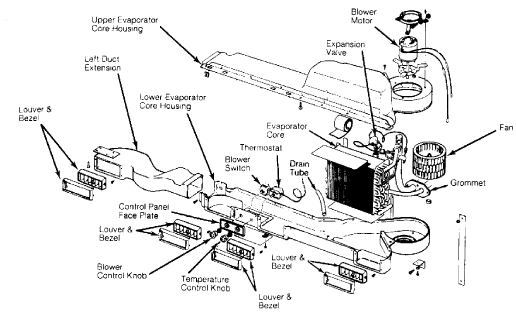
Fig. 1: Exploded View of Wrangler Evaporator Housing
Courtesy of Chrysler Motors.
EVAPORATOR-BLOWER HOUSING &
áHEATER & EVAPORATOR CORES
NOTE: The following procedures are for vehicles with A/C-heater
ásystems only. For replacement of heater cores on vehicles
áwith heater systems only, see HEATER SYSTEMS, JEEP article.
áRemoval (Cherokee, Comanche & Wagoneer)
á1) Disconnect battery ground. Discharge A/C system using
approved refrigerant recovery/recycling equipment. Disconnect A/
C
hoses from expansion valve. Drain cooling system. Disconnect heater
hoses at core tubes. Disconnect blower motor wires and vent tube.
á2) Remove console (if equipped). Remove lower instrument
panel. Disconnect electrical connectors at A/C relay, blower motor
resistors and A/C thermostat. Disconnect vacuum hose at vacuum motor.
Cut plastic retaining strap holding evaporator-blower housing to
heater core housing.
á3) Disconnect blend-air heater control cable. Detach clip at
rear of blower housing flange and remove retaining screws. Remove
housing attaching nuts from studs on engine compartment side of dash
panel. Remove evaporator drain tube.
á4) Remove right kick panel. Detach instrument panel support
bolt. Gently pull on right side of dash, then rotate housing downward
and toward rear of vehicle to disengage housing studs from dash panel.
Remove evaporator-blower housing.
á5) To remove heater core, detach retaining screws. Remove
heater core by pulling straight out of housing. To remove evaporator
core, detach top housing retaining screws, then remove top of
evaporator housing.
á6) Remove thermostatic switch and capillary tube. Detach
2
evaporator retaining screws and lift evaporator core from housing.
Remove expansion valve from evaporator.
áInstallation
á1) To install components, reverse removal procedure. When
installing evaporator core, install thermostatic switch and capillary
tube before installing top of housing.
á2) When installing heater core, ensure seal is properly
cemented in place to prevent it from moving when blower assembly is
installed. Evacuate, leak test, recharge and check A/C system
operation.
NOTE:
The evaporator housing mounting location is similar to
áWrangler, except blower motor is mounted horizontally to
áfirewall.
áRemoval (Wrangler)
á1) Discharge system using approved refrigerant
recovery/recycling equipment. Disconnect inlet line at compressor.
Disconnect hose, at quick-disconnect coupling, between receiver-drier
and evaporator. Remove hose clamps and dash grommet retaining screws.
See Fig. 2.
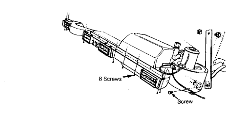
Fig. 2: Wrangler Evaporator Housing Mounting Screw Locations
Courtesy of Chrysler Motors.
NOTE:
It is not necessary to discharge system to service blower
motor. Evaporator housing may be lowered from instrument
panel to gain access to blower motor mounting screws.
á2) Remove screws attaching evaporator housing to instrument
panel and mounting bracket. Lower evaporator housing and pull hoses
and grommet through opening.
áInstallation
áTo install, reverse removal procedure. Evacuate, leak test,
recharge and check A/C system for proper operation.
EXPANSION VALVE
áRemoval (Cherokee, Comanche & Wagoneer)
áDischarge A/C system using approved refrigerant
recovery/recycling equipment. Disconnect A/C hoses from expansion
valve. Disconnect expansion valve from evaporator core inlet and
outlet tubes. Remove expansion valve.
áInstallation
áTo install, reverse removal procedure. Evacuate, leak test,
recharge and check A/C system operation.
NOTE:
The expansion valve is pre-set and should not be adjusted.
A
faulty valve requires replacement.
áRemoval (Wrangler)
á1) Discharge system using approved refrigerant
recovery/recycling equipment. Remove evaporator housing. Remove
insulation wrapped around suction line and expansion valve.
á2) Mark capillary tube location on suction line. Disconnect
inlet and outlet connections, capillary tube clamp and equalizer tube.
Remove expansion valve.
áInstallation
á1) Clean suction line to provide positive contact with
replacement expansion valve capillary tube. Connect inlet and outlet
hoses. Clamp capillary tube securely at marked position and connect
equalizer tube.
á2) Wrap expansion valve and line with insulation. Install
evaporator housing assembly. Evacuate, leak test, recharge and check
A/C system operation.
TEMPERATURE CONTROL THERMOSTAT
áRemoval (Cherokee, Comanche & Wagoneer)
á1) Disconnect battery ground. Remove console (if equipped)
.
Remove lower instrument panel. Disconnect electrical connection at
thermostat. See Fig. 3.
á2) Remove capillary tube retaining screw. Remove thermostat
retaining screws. Remove capillary tube from tube guide hole.
áInstallation
á1) To install, feed capillary tube through tube guide hole
until Red tape on capillary tube just enters hole in housing. Install
capillary tube retaining screw and clip.
á2) Install thermostat retaining screws and attach electrical
connection. To complete installation, reverse removal procedure.
CAUTION: Handle capillary tube with care to avoid bends or kinks
which could cause thermostat to malfunction.
áRemoval (Wrangler)
Remove evaporator housing assembly. Remove lower cover.
Carefully remove thermostat and capillary tube.
NOTE:
On Wrangler models, servicing temperature control thermostat
requires disassembly of evaporator core housing.
áInstallation
áTo install, insert capillary tube into evaporator coil
a
minimum of 2" (51 mm). See Fig. 4. Install thermostat and evaporator
housing lower cover.
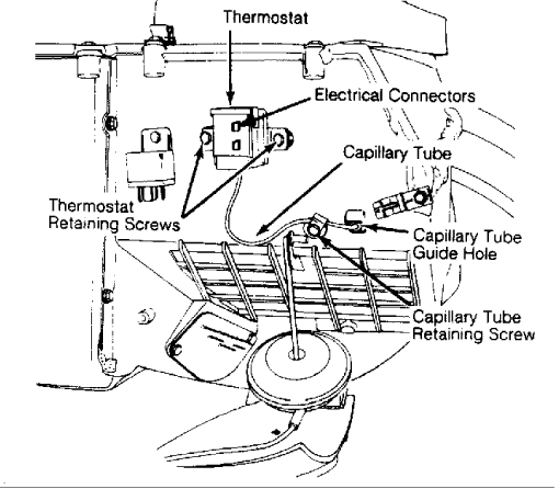
Fig. 3: Capillary Tube & Temperature Control Thermostat Locations
Cherokee, Comanche and Wagoneer locations are shown.
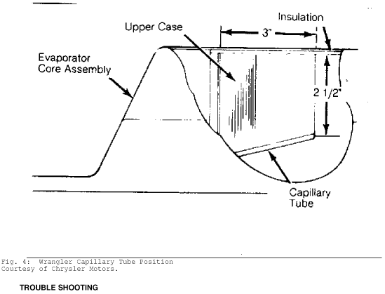
Fig. 4: Wrangler Capillary Tube Position
Courtesy of Chrysler Motors.
TROUBLE SHOOTING
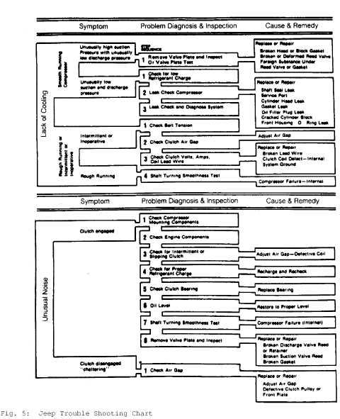
Fig. 5: Jeep Trouble Shooting Chart
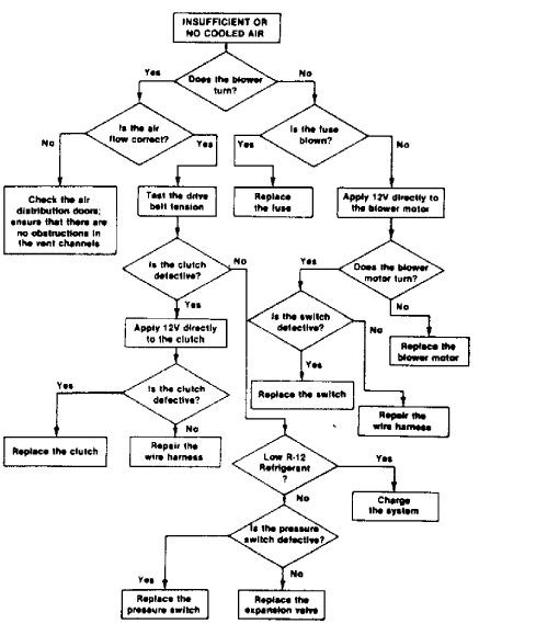
Fig. 6: Jeep Trouble Shooting Flow Chart
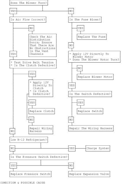
CONDITION & POSSIBLE CAUSE
Compressor Runs Rough
* Incorrect oil or refrigerant level.
* Internal compressor damage.
Compressor Intermittent or Inoperative
* Drive belt slipping.
* Faulty clutch air gap.
* Clutch coil wiring broken or frayed.
Noisy Compressor
* Mounting bolts loose.
* Clutch slipping.
* Improper charge in system.
* Bad clutch or pulley bearings.
* Incorrect oil level.
* Valve plate damaged.
* Piston slap.
Excessive Vibration
* Incorrect belt tension.
* Clutch loose.
* Pulley misaligned.
* System overcharged.
A/C Air Flow Stops on Acceleration
* Defective vacuum storage tank.
* Vacuum line separated or defective.
* Vacuum switch defective.
* Vacuum leak.
High Suction Pressure with Very Low Discharge Pressure
* Valve plate or gasket broken or deformed.
Very Low Suction and Discharge Pressure
* Low refrigerant charge.
* Compressor leak.
* System leak.
Heater Control Valve Does Not Close with Vacuum Applied
* Faulty heater control valve.
No Vacuum at Heater Control Valve with Lever at Extreme Left
* Vacuum source hose disconnected.
* Leaking vacuum hose.
* Faulty check valve.
* Control panel switch defective or misadjusted.
Frozen Evaporator Core
* Faulty thermostat.
* Thermostat capillary tube improperly installed.
* Thermostat not adjusted properly.
Condensation Dripping in Passenger Compartment
* Drain hose plugged or improperly installed.
* Insulation missing or improperly installed.
------------------------------------------------------------------------------------------------------------------------------------------.
TESTING
Note:
The following test applies to all Jeep models except Cherokee
and Wagoneer.
System Charge Test
á1) To check system refrigerant level, a sight glass has been
incorporated into the receiver-to-evaporator hose at the receiver end.
A continuous stream of bubbles will appear in the sight glass of
a
system that is not properly charged. However, both properly charged
systems and discharged systems will appear the same because of a lack
of bubbles.
á2) To test for discharge condition, cycle the clutch off and
on with engine at 1500 RPM. When clutch is off, bubbles will appear if
there is refrigerant in the system. If no bubbles appear, system is
discharged. If discharged, leak test, repair and recharge system.
A/C SYSTEM OPERATION CHART & VACUUM DIAGRAM
A/C SYSTEM OPERATION TABLE
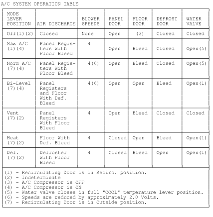
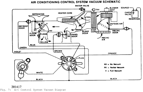
Fig. 7: A/C Control System Vacuum Diagram