TUNE-UP - 4-CYL
1988 Jeep Cherokee
1988 Jeep 4 Tune-Up TUNE-UP
All Models
IDENTIFICATION
ENGINE IDENTIFICATION
Engine can be identified by the 4th character of the Vehicle Identification Number (VIN). The VIN is stamped on a plate attached to top left corner of instrument panel.
ENGINE CODES
Engine Code
2.5L (150") TBI H
TUNE-UP NOTES
NOTE: When performing tune-up procedures described in this article, the following notes and precautions must be followed.
Due to late changes and corrections, always refer to Emission Control Label in engine compartment before attempting tune-up. If manual and label differ, always use label specifications.
EPA High Altitude emission standards apply to vehicles sold in certain areas outside California which have an elevation above 4000 feet.
When performing tune-up on vehicles equipped with catalytic converter, do not allow or create an engine misfire in one or more cylinders for an extended period of time. Damage to converter may occur due to loading converter with unburned fuel.
TESTING
ENGINE COMPRESSION
Test compression with all spark plugs removed, throttle plates and choke valve wide open and engine at normal operating temperature. Crank engine through at least 5 compression strokes before recording reading.
COMPRESSION SPECIFICATIONS
Application Specification
Compression Ratio 9.2:1
Compression Pressure 155-185 psi (10.9-13.0 kg/cm)
Max. Variation Between Cylinders 30 psi (2.1 kg/cm)
SPARK PLUGS
SPARK PLUG TYPE
Application
Champion No.
2
. 5L RC-12LYC
SPARK PLUG SPECIFICATIONS
Application Gap: In. (mm) Torque: Ft. Lbs. (N.m)
2.5L 035 (.89) 7-15 (9-20)
HIGH TENSION WIRE RESISTANCE
Do not puncture spark plug wires with any type of probe. Remove spark plug wire and check resistance with an ohmmeter.
ADJUSTMENTS
VALVE ARRANGEMENT
* E-I-I-E-E-I-I-E (Front-to-rear). VALVE CLEARANCE
All models are equipped with hydraulic lifters, which should be adjusted to zero lash.
IGNITION COIL WIRE
Remove ignition coil wire from coil and distributor cap. Check terminals for corrosion and clean if necessary. Check coil wire resistance. Replace wire if resistance is excessive.
HIGH TENSION WIRE RESISTANCE (OHMS)
Wire Length (In.) Minimum Maximum
0-15 3000 10,000
15-25 4000 15,000
25-35 6000 20,000
Over 35 8000 25,000
DISTRIBUTOR
All models are equipped with a Renix solid state ignition module. Renix system uses a TDC sensor mounted near the flywheel. The distributor consists of a cap and rotor. Its only function is to distribute high voltage to appropriate spark plug. No adjustments are required on either system.
 9087
9087
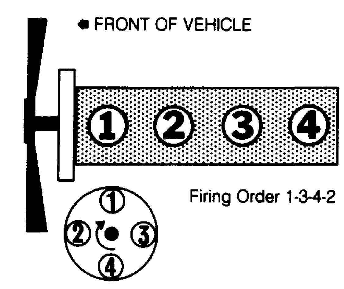
Fig. 1: 2 . 5L Firing Order & Distributor Rotation
IGNITION TIMING
NOTE: No adjustment is possible on models with Renix ignition.
HOT (SLOW) IDLE RPM
NOTE: Adjust ISC motor plunger only after replacing ISC motor.
Idle Speed Control (ISC) Motor Plunger
1) Remove air cleaner, turn off A/C (if equipped) and warm engine to normal operating temperature. Connect tachometer negative lead to diagnostic connector terminal "D1-3" and positive lead to connector terminal "D1-1". See Fig. 2. Turn ignition off. ISC plunger should fully extend.
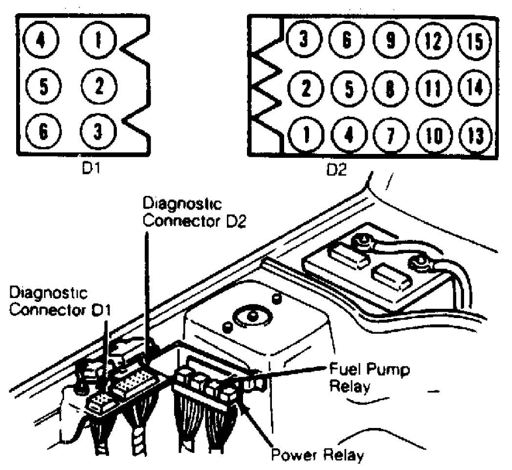
Fig. 2: TBI Diagnostic Connector & Terminal ID Courtesy of Chrysler Motors.
With
plunger extended, disconnect ISC motor electrical
connector.
Start engine. Engine idle speed should be 3300-3700 RPM.
If
not, turn plunger hex head to obtain
3500 RPM. See Fig. 3.
To fully
retract ISC motor, hold closed throttle switch
plunger inward
while opening throttle. Closed throttle switch plunger
should not
touch throttle lever when throttle is closed. If this
occurs,
check linkage and/or cable for binding.
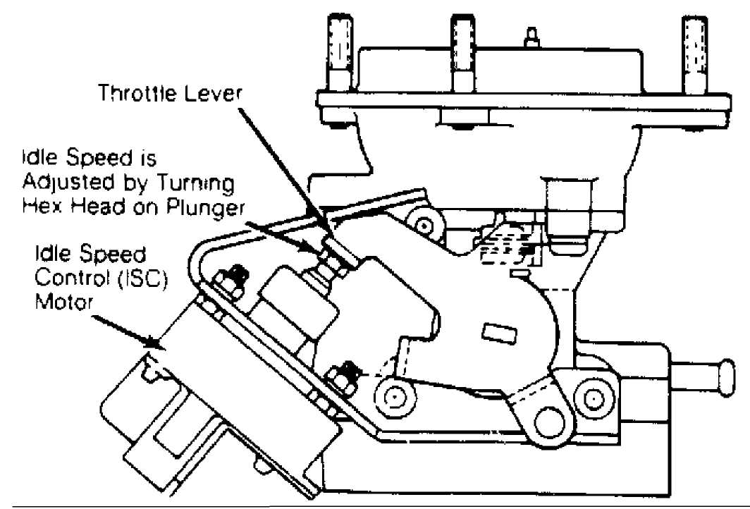
Fig. 3: TBI Idle Speed Control (ISC) Motor Adjustment Courtesy of Chrysler Motors.
4) Connect ISC motor connector. Turn ignition off for 10 seconds. ISC motor should fully extend. Restart engine. Engine speed should momentarily be about 3500 RPM and return to idle speed. Turn ignition off and disconnect tachometer. Apply sealant to adjustment screw threads. Install air cleaner.
IDLE SPEED (RPM)
Application
2.5L TBI (ISC Plunger Extended)
Curb Idle
3500
NOTE: Holding plunger inward may create an intermittent trouble code in ECU memory. To clear ECU memory, turn ignition off and disconnect negative battery cable for 10 seconds.
THROTTLE POSITION SENSOR (TPS) ADJUSTMENT
NOTE: On some models, it may be necessary to remove throttle body from intake manifold, to access sensor wiring harness.
Automatic Transmission
Locate
the square TPS connector. Note connector terminal
identification
stamped on the back of the connector. Turn ignition on.
Connect voltmeter through back of wiring harness
connector. Connect negative voltmeter lead to terminal "D" and positive voltmeter lead to terminal "A" to check input voltage. DO NOT disconnect TPS connector.
Hold
throttle plate closed against idle stop and note
voltage. Input
voltage should be approximately 5 volts.
Disconnect
voltmeter positive lead and
connect to terminal "B" to measure output
voltage.
With
throttle plate closed, measure the output voltage.
The output
voltage should be approximately .2 volts.
If output voltage
is not within specification, loosen TPS
retaining screws.
Partially
tighten one retaining screw. Rotate TPS to
obtain correct output
voltage. Tighten retaining screws once correct
voltage is
obtained.
Manual Transmission
Turn
ignition on. Connect voltmeter through back of wiring
harness
connector. Connect negative voltmeter lead to terminal "B"
and
positive voltmeter lead to terminal
"C". DO NOT disconnect TPS
connector.
See Fig. 4.
Rotate
and hold throttle plate in wide open position.
Ensure throttle
linkage contacts stop. Note voltmeter reading. Voltage
reading
should be 5 volts at wide open throttle.
Return throttle plate
to closed
throttle position. Disconnect voltmeter positive lead from
sensor
terminal "C" and connect it to terminal "A".
Rotate
and hold throttle plate in wide open position.
Ensure throttle
linkage contacts stop. Note voltmeter reading. Output
voltage
should be 4.6-4.7 volts. If voltage is not
as specified,
loosen sensor mounting
screw. Loosen upper sensor mounting screw for
small
adjustments and lower screw for large adjustments.
Adjust
sensor. Tighten sensor mounting screws. Remove
voltmeter and
return throttle plate to closed position. Replace sensor
if
specified output voltage cannot be obtained.
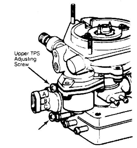 Lower
TPS
Lower
TPS
Adjusting
Screw
Fig. 4: Adjusting Throttle Position Sensor (Man Trans) Courtesy of Chrysler Motors.
IDLE MIXTURE ADJUSTMENT
NOTE: Idle mixture adjustment is not possible on TBI models. COLD (FAST) IDLE RPM
NOTE: Fast idle is not adjustable on TBI models.
SERVICING
EMISSION CONTROL
See EMISSIONS section.
SPECIFICATIONS
IGNITION
Distributor
All models are equipped with Renix solid state ignition.
IGNITION COIL RESISTANCE - OHMS @ 75F (24C)
Application Primary Secondary
2.5L 4-.8 2500-4000
FUEL SYSTEM
FUEL INJECTION
Application Model
2. 5L Renix TBI
Fuel Pump
The 2.5L engine with TBI uses an electric fuel pump located in the tank.
FUEL PUMP SPECIFICATIONS
 Application Pressure:
psi (kg/cm) Volume: Pts. (L)
Application Pressure:
psi (kg/cm) Volume: Pts. (L)
2.5L (TBI) 14.5 (1.0) N/A
BATTERY
BATTERY SPECIFICATIONS
Application Cold Cranking Reserve Capacity
** (1) Amps Minutes
Standard 421 75
Optional 452 81
(1) - At 0F (-18C).
STARTER
All 2 . 5L engines use a Bosch positive engagement starter. STARTER SPECIFICATIONS
Application
Volts Amps Test RPM
2.5L
12 75 2900
ALTERNATOR
All 2.5L engines use a Delco-Remy 10SI or 12SI alternator with integral regulator.
ALTERNATOR SPECIFICATIONS
Application Field Current Rated Amp
** Draw @ 12 Volts Output
Standard 4.0-5.0 Amps 56
Optional 4.0-5.0 Amps 66
Optional 4.0-5.0 Amps 78
ALTERNATOR REGULATOR
All 2.5L models use Delco-Remy nonadjustable regulators, integral with alternator.
REGULATOR OPERATING VOLTAGE @ 80F (27C)
Application Voltage
2.5L 13.9-14.9
BELT ADJUSTMENT
BELT ADJUSTMENT -
TENSION IN LBS. (KG) USING STRAND TENSION
GAUGE
Application New
Belt Used Belt
"V" Belts (1) 125-155 (57-70) 90-115 (41-52)
Serpentine 180-200 (82-91) 140-150 (64-68)
(1) - Adjust new P/S belt to 120-140 lbs. (54-64 kg).
SERVICE INTERVALS
REPLACEMENT INTERVALS
Component Interval (Miles)
Air Filter 30,000
Fuel Filter 30,000
Engine Oil & Filter 7500
PCV Valve 30,000
Spark Plugs 30,000
CAPACITIES
FLUID CAPACITIES
Application
Quantity
Auto. Trans. (Dexron II)
Wrangler 8.0 qts . (7 . 6L)
All Others 8.5 qts. (8.0L)
Cooling System
Wrangler 9.0 qts . (8 . 5L)
All Others 10.0 qts. (9.5L)
Crankcase (Includes Filter) 4.0 qts. (3.8L)
Drive Axle
Front 2.5 pts. (1.2L)
Rear
Commanche
Standard Capacity 2 . 5 pts. (1.2L)
Metric Ton Axle 4.8 pts . (2 . 3L)
All Others 2.5 pts. (1. 2L)
Fuel Tank
Cherokee & Wagoneer
Standard 13.5 gals. (51L)
Optional 20 gals. (76L)
Comanche
Standard 16 gals. (60L)
Optional 23.5 gals. (89L)
Wrangler
Standard 15 gals. (57L)
Optional 20 gals. (75L)
Manual Transmission
AX4 7.8 pts. (3.7L)
AX5 7.4 pts. (3.5L)
BA 10/5 3.5 pts. (1.6L)
Transfer Case (Dexron II)
Wrangler 3.2 5 pts. (1. 5L)
All Others
Command Trac 2.2 pts . (1. 0L)
Select Trac 3.0 pts. (1.4L)
SYSTEM REFRIGERANT CAPACITIES
Application Ozs.
All Models 36