STEERING COLUMN SWITCHES
1988 Jeep Cherokee
1988 STEERING
Jeep Steering Column Switches
All Models
REMOVAL & INSTALLATION
TURN SIGNAL & HAZARD FLASHER SWITCHES
Removal & Installation
Place
front wheels in straight-ahead position. Disconnect
battery
negative cable. Remove the steering wheel. Refer to the
STEERING
WHEEL & HORN REMOVAL article.
On
models with A/T, place selector lever in "PARK"
position.
Remove selector lever retaining pin and lever. Using 2
screwdrivers,
remove lock plate cover. On models with tilt column,
remove
tilt lever.
Using
Plate Compressor (J-23653-A), compress
lock plate.
If shaft has metric threads, use Metric Forcing Screw
(J-23653-4)
prior to installing compressor on shaft. Remove and
discard lock plate
snap ring. Remove plate compressor
NOTE: The lock plate is under strong spring tension. DO NOT attempt to remove snap ring without using lock plate compressor.
Remove
lock plate, canceling cam, upper bearing preload
spring,
spring seat and bearing race (thrust washer on some models).
Depress
hazard warning switch while unscrewing from column.
On
vehicles with A/T, use a paper clip to compress lock
tab
retaining shift quadrant light wire in connector block.
Disconnect
wire. On all models, remove
turn signal lever attaching screw and
lever.
On
vehicles with cruise control, disconnect 2 of
4 wires
at
switch connector. Fold wires back along harness. Tape wires
to
harness. Tape a string to harness to
aid in removal.
Disconnect
turn signal switch wire harness at bottom of
steering column.
Tape around turn signal switch harness connector to
aid in
removal. Remove turn signal switch attaching screws. Remove
switch.
To install, reverse removal procedure.
LOCK CYLINDER
Removal
Remove
horn button and steering wheel. Refer to the
STEERING
WHEEL & HORN REMOVAL article. Remove
turn signal switch.
Remove key warning buzzer switch and contacts
as an assembly, using
needle-nose
pliers.
On
models with standard column, turn ignition lock
cylinder
(clockwise) 2 detent positions beyond the
"OFF/LOCK"
position. On models with tilt column, turn
lock cylinder to "LOCK"
position.
On all models, compress lock cylinder retaining tab and
remove
lock cylinder from housing. See Fig. 1.
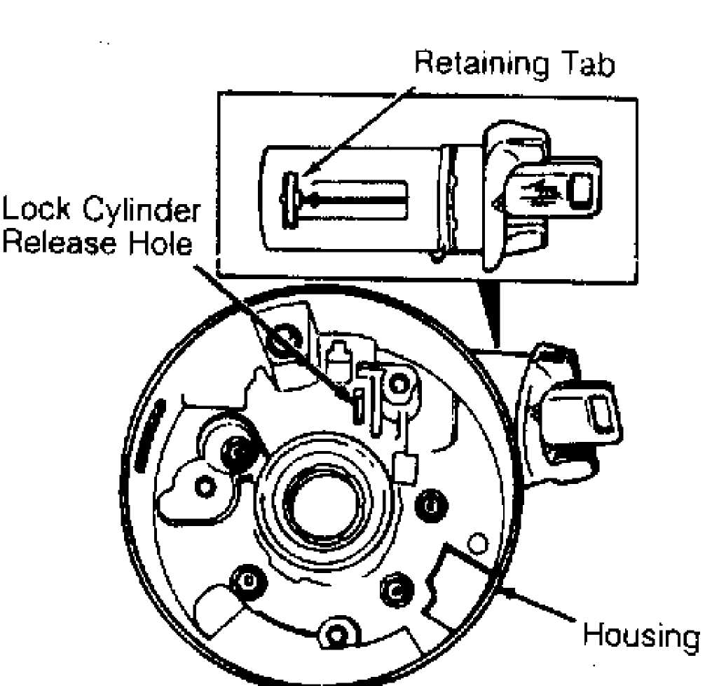
Fig. 1: Removing Jeep Lock Cylinder Courtesy of Chrysler Motors
Installation
To
install, insert key in lock cylinder. Hold cylinder
sleeve while
turning key clockwise until key stops. Align lock
cylinder
retaining tab with keyway in housing. Insert cylinder into
housing.
Push lock
cylinder inward until it contacts lock sector.
Rotate cylinder to
engage it with lock sector. Push lock cylinder
inward until
cylinder retaining tab engages in housing groove. To
complete
installation, reverse removal procedure.
IGNITION SWITCH
Removal (Cherokee, Wagoneer & Wrangler)
Remove lower instrument panel trim panel. Insert key in lock
cylinder. Turn cylinder to "OFF-UNLOCK" position. Disconnect switch from remote rod. Disconnect harness connectors at switch. Remove switch.
Installation
Move switch slider to "ACC" position. Engage remote rod in switch slider. Position switch on column, taking care not to move slider. Hold key in "ACC" position while pushing switch down slightly to remove slack in actuator rod. Install attaching screws. Connect harness connectors.
IGNITION SWITCH
Removal (Comanche & Grand Wagoneer)
Remove lower instrument panel trim panel. Insert key in lock cylinder. Turn cylinder 2 positions beyond the "OFF-UNLOCK" position. Disconnect switch from remote rod. Disconnect harness connectors at switch. Remove switch.
Installation
Move switch slider to "ACC" position. Move switch slider back 2 clicks to "OFF-UNLOCK" position. Engage remote rod in switch slider. Position switch on column. DO NOT move slider while positioning switch. Install attaching screws. Connect harness connectors.
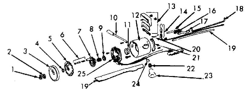
10 Turn Signal Lever
Thrust Cup
Housing
Indicator Assembly
Indicator Light
Lock Bolt
Spring Washer
Lockflack
Steering Wheel Retaining Nut
Washer
Lock Plate Cover
Snap Ring
Lock Rate
Horn Contact Pin, Retainer & Spring
Cancelling Cam
Upper Bearing Preioad Spring
Thrust Washer
Fig. 2: Exploded View of Jeep Steering Column Switch Assemblies Courtesy of Chrysler Motors
TROUBLE SHOOTING
Remote Rod
Harness Cover
Rack Preload Spring
Shift Gate Lock
Sector
Ignition Lock Cylinder
Hazard Knob
Turn Signal Switch
Refer to TROUBLE SHOOTING GENERAL TROUBLE SHOOTING section.
- BASIC PROCEDURES article in the