CRUISE CONTROL SYSTEM
1988 Jeep Cherokee
1988 Cruise Control Systems JEEP CRUISE COMMAND
All Models
DESCRIPTION & OPERATION
Jeep vehicles use an electro-mechanical servo system. The system consists of a control module, speed sensor, servo, control switch assembly, vacuum storage canister, check valve and release system. Release system consists of a mechanical vacuum vent valve and brake and clutch (M/T) release switches.
Cruise control switch is an integral part of turn signal switch lever and consists of 2 separate switches. First is an "ON-OFF" and "RESUME" slide switch located on flat of directional switch lever.
Second is "SET/COAST" push button switch located at end of directional switch lever. To engage system, move slide switch to "ON" position and accelerate to desired speed. Depress and release "SET/COAST" button on end of switch lever. System will now maintain selected speed.
System will automatically disengage when brake or clutch pedal is depressed. It can be re-engaged to previously selected speed by accelerating to 30 MPH and moving slide switch to "RESUME" position, then releasing switch.
NOTE: When slide switch is moved to "OFF" position, pre-set speed of "RESUME" function is canceled from memory and must be reset when system is reactivated.
Higher speed can be set by pressing on accelerator pedal until new speed is reached and then pushing "SET/COAST" button. Lower speed can be obtained by lightly depressing brake pedal, allowing the vehicle to slow to desired speed and then depressing and releasing "SET/COAST" button.
CONTROL MODULE
Control module receives input voltage representing vehicle speed from speed sensor, which is driven by the speedometer cable. Control module has a low speed circuit that prevents operation at speeds below 30 MPH. See Fig. 1.
SERVO
Servo is controlled by control module and uses manifold vacuum to control throttle. Bead-link chain connects servo cable to throttle linkage. See Fig. 1.
CONTROL SWITCH
Control switch assembly is an integral part of turn signal switch lever. See Fig. 1.
RELEASE SYSTEM
Release system deactivates cruise control system when brake or clutch pedal is depressed. Either servo vent valve or mechanical vacuum vent switch admits atmospheric pressure into servo when brake pedal is depressed.
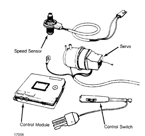
Fig. 1: Cruise Control System Components Courtesy of Chrysler Motors.
TROUBLE SHOOTING
NOTE: Vehicles with computerized engine controls, should be tested for stored computer codes. Codes and related problems must be repaired prior to cruise control diagnosis and repair. For additional information, see COMPUTERIZED ENGINE CONTROLS section.
SYSTEM WILL NOT ENGAGE
Restricted vacuum hose or no vacuum. Control switch or control module defective. Speed sensor defective. Clutch or brake light switch defective or misadjusted. Brake light switch wire disconnected. Open circuit between brake light switch and brake lights.
RESUME FEATURE INOPERATIVE
Defective servo ground connection. Defective control switch. ACCELERATE FUNCTION INOPERATIVE
Accelerate circuit in control module inoperative. Defective control switch.
SYSTEM RE-ENGAGES WHEN BRAKE PEDAL IS RELEASED
Defective control module. Mechanical vent valve not opening. Kink in mechanical vent valve hose. Brake light switch defective.
CARBURETOR THROTTLE DOES NOT RETURN TO IDLE POSITION
Improper linkage adjustment. ROAD SPEED CHANGES 2 MPH OR MORE WHEN SETTING SPEED
Centering adjustment wrong. Servo link misadjusted.
ENGINE ACCELERATES WHEN STARTED
Improper servo chain adjustment. Vacuum hose connections reversed at servo. Defective servo.
SYSTEM DISENGAGES ON LEVEL ROAD WITHOUT APPLYING BRAKES
Loose wire connection. Loose vacuum hose connection. Servo linkage broken. Defective brake light switch.
ERRATIC OPERATION
Reverse polarity of system wiring. Defective servo. Defective control module.
VEHICLE CONTINUES TO ACCELERATE WHEN "SET" BUTTON IS RELEASED
Servo or control module defective. SYSTEM ENGAGES BUT SLOWLY LOSES SET SPEED
Air leak at connections or in vacuum hoses. Air leak on vent valve on brake pedal.
ADJUSTMENTS
CONTROL MODULE ADJUSTMENT
NOTE: Control module adjustments are preset by manufacturer. If
other components in system appear to be functioning properly
and cruise control remains inoperative, perform following adjustments to determine if control module is functional.
1) Remove control module attaching screws or tie straps and
move control module downward for adjustment access. Turn centering
adjustment screw to 10 o’clock position. Turn low speed adjustment
screw to 10 o’clock position. Turn sensitivity adjustment screw fully
clockwise.
CAUTION: Adjustment potentiometers are extremely delicate. Carefully insert screwdriver and do not push or turn screws excessively hard. Maximum movement is 3/4 turn.
Adjustments are not precisely correct for vehicle, but are
acceptable to determine if control module is functioning. Perform
precise adjustments by road testing vehicle on level road. If
adjustments have no effect on cruise control, replace control module.
If actual engagement speed is 2 MPH or more above selected
speed, stop vehicle and turn centering screw 1/16 of a turn
counterclockwise. Recheck engagement speed and adjust as necessary.
If engagement speed is 2 MPH or more below selected speed,
turn centering screw 1/16 of a turn clockwise. Recheck engagement
speed and adjust as necessary.
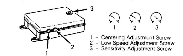
Fig. 2: Control Module Adjustment Screws Courtesy of Chrysler Motors.
VACUUM VENT VALVE
Depress brake or clutch pedal and hold in depressed position. Move vacuum vent valve toward bracket on pedal as far as possible. Release brake or clutch pedal.
TESTING
NOTE: Vehicles with computerized engine controls, should be tested for stored computer codes. Codes and related problems must be repaired prior to cruise control diagnosis and repair. For additional information, see COMPUTERIZED ENGINE CONTROLS section.
PRELIMINARY INSPECTION
Ensure cruise control wire harness is properly connected to
control module before starting diagnosis or repair procedure, as this connection is disturbed when Cruise Command System Tester (AM PC-1-R) is used. Poor connection at this point may be improperly diagnosed as control module malfunction.
Brake light and clutch switches should be properly adjusted. Ensure that all vacuum lines are correctly routed and tightly connected.
CRUISE COMMAND SYSTEM TESTS
Testing is performed with Cruise Command System Tester (AM PC-1-R). Remove wire harness connector from control module. Connect tester to wire harness connector. Perform tests as part of service diagnosis to determine cause and correction of system malfunction. Various tester lights are associated with specific components, circuits, etc.
CONTROL SWITCH CONTINUITY
Wrangler
NOTE: Voltage checks should show battery voltage. If resistance readings are incorrect, check circuit for an open or a short. Cruise control module terminal No. 1 grounds through connector at engine block.
Light No. 1 "OFF" (Set Switch)
With control switch in "ON" position, check for battery voltage between HAZ/STOP and in-line fuse, terminal No. 14 and ground terminal No. 1
Light No. 2 "OFF" (Control Switch & Speed Sensor) With control switch in "ON" position, check for battery voltage between HAZ/STOP and in-line fuse, terminal No. 5 and ground terminal No. 1. With ignition switch in "OFF" position, check resistance between terminals No. 2 and No. 3. Resistance should be 15-50 ohms.
Light No. 3 "OFF" (Brake Light Ground)
With ignition switch in "ON" position, install jumper wire between terminals No. 7 and No. 13. If brake lights do not turn on, check fuses and brake light switch connections.
Light No. 4 "OFF" (Throttle Position Feedback Sensor) With ignition switch in "ON" position, check for battery
voltage between gauge fuses at terminals No. 7 and No. 1.
With ignition switch in "OFF" position, check resistance
between terminals No. 2 and No. 11. Resistance should be 2400-4000
ohms. At idle resistance should be 2800-4300 ohms and at wide open
throttle resistance should be 4000 ohms.
Light No. 5 "OFF" (Resume/Accel/Vent Valve) With control switch in "RESUME/ACCEL" position, check for battery voltage between HAZ/STOP and in-line fuse, terminal No. 10 and ground terminal No. 1. With ignition switch in "OFF" position, check resistance between terminals No. 6 and No. 12. Resistance should be 30-50 ohms. Resistance between terminals No. 6 and ground, and terminal No. 12 and ground should be infinite (open).
Light No. 6 "OFF" (Resume/Accel/Charge Valve) With control switch in "RESUME/ACCEL" position, check for battery voltage between HAZ/STOP and in-line fuse, terminal No. 10 and ground terminal No. 1. With ignition switch in "OFF" position, check resistance between terminals No. 4 and No. 12. Resistance should be
30-50 ohms. Resistance between terminals No. 4 and ground, and terminal No. 12 and ground should be infinite (open).
WRANGLER CRUISE CONTROL TESTING
Conditions Lights "ON"
Control Switch "ON" & Set Switch Depressed No. 1
Control Switch "ON" No. 2
Ignition "ON" & Brake or Clutch Pedal Depressed No. 3 & No. 4
Cruise Control & Resume/Accel "ON" No. 5 & No. 6
Cruise & Resume/Accel "ON" & Engine Running (1) No. 5 & No. 6
(1) - Servo will pull throttle wide open. Keep RPM at a safe level by releasing cruise control switch.
Except Wrangler
Use 12-volt test light to test control switch continuity. Connect test light to wires as indicated in CONTROL SWITCH CONTINUITY TEST CHART. See Figs. 3 or 4.
SET/COAST (S/C) SW | POSITION SLIDER | 1-2 | 1-3 | 1-4 | 2-3 | 2-4 | 3-4 |
Normal | Oft | 0 | î | Î | Î | Î | î |
Normal | On | Î | î | Î | î | ń | Î |
Normal | R/A | Ń | î | ń | Î | ń | Î |
Depressed | Off | Î | î | Î | ń | î | î |
Depressed | On | Î | î | î | ń | ń | ń |
Depressed | R/A | ń | ń | ń | ń | ń | ń |
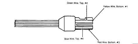
Fig. 3: Cherokee, Comanche & Wagoneer Control Switch Continuity Test
Chart
Courtesy of Chrysler Motors.
Ń - Closed Î - Open
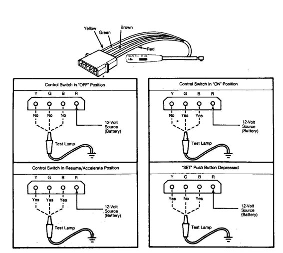
Fig. 4: Grand Wagoneer Control Switch Continuity Test Chart Courtesy of Chrysler Motor.
CORRECT POWER SOURCE
Cherokee, Comanche & Wagoneer
With ignition switch and control switch "OFF", all test
lights should be off. If any light is on, check Brown (7) wire is not
connected directly to source of voltage.
Check for bad control switch. With ignition switch in
"OFF" position, and control switch "ON". Light No. 2 should be on and
lights No. 1, 3, 4, 5 and 6 should be off.
If light No. 2 is off, check speed sensor continuity,
check speed sensor terminals to Gray and Drk. Blue wires, and check
that terminals No. 2, 3, 5 and 7 (Gray, Drk. Blue and Lt. Green wires
are not grounded).
Grand Wagoneer
With ignition and control switches in "OFF" position, test lights should be off. If one or more lights are on, remove Brown (5) wire at control module connector and check for direct source of voltage or repair defective control switch.
SYSTEM ELECTRICAL CONTINUITY
Cherokee, Comanche & Wagoneer
With ignition and control switches in "ON" position,
lights No. 2, 3 and 4 should be on. Lights No. 1, 5 and 6 should be
off. If light No. 2 is off, check speed sensor continuity, check speed
sensor terminals to Gray and Drk. Blue wires, and check terminals No.
2, 3, 5 and 7 (Gray, Drk. Blue and Lt. Green wires are not grounded).
If light No. 3 is off, check brake light switch and all
Brown, Lt. Blue and Lt. Green wire connections. If light No. 4 is off,
check terminals No. 2 and No. 11 at control module connector. Check
continuity of throttle position feedback rheostat of servo.
Grand Wagoneer
With ignition and control switches in "ON" position,
lights No. 1, 2, 3, and 4 should be on. Lights No. 5 and 6 should be
off. If light No. 1 is off, check for blown fuse in brake light switch
to control switch circuit. Check Red, Brown and Green wires at control
switch for continuity to switch. Check Drk. Green wire (14) at control
module connector for continuity to control module.
If light No. 2 is off, check speed sensor for correct
output voltage. Check Gray and Drk. Blue wire at speed sensor
connector for continuity to control module connector. Check terminals
No. 2, 3, 5 and 7 at control module connector for proper connection to
wires.
If light No. 3 is off, check brake and clutch switch
adjustment. If light No. 4 is off, check for defective connection at
terminals No. 2 and 11 on control module connector. Check operation of
throttle position feedback rheostat on servo.
COAST CONTINUITY TEST
Cherokee, Comanche & Wagoneer
With ignition and control switches in "ON" position,
depress and hold "SET/COAST" button. Lights No. 1, 2, 3 and 4 should
be on. Lights No. 5 and 6 should be off. If light No. 1 is off, check
voltage from brake light switch, check 4-amp in-line fuse of Pink
wire, and check Pink, Brown and Drk. Green wires at control switch
connector and Drk. Green (14) wire at control module connector for
good connections.
If light No. 2 is off, check speed sensor continuity,
check speed sensor terminals to Gray and Drk. Blue wires, and check
terminals No. 2, 3, 5 and 7 (Gray, Drk. Blue and Lt. Green wires) for
ground.
If light No. 3 is off, check brake light switch, check all
Brown, Lt. Blue and Lt. Green wire connections. If light No. 4 is off,
check terminals No. 2 and 11 at control module connector, and check
continuity of throttle position feedback rheostat of servo.
SERVO CHARGE VALVE SOLENOID CONTINUITY
CAUTION: If engine is running, servo will move throttle to wide open position.
Grand Wagoneer
1) With ignition and control switches in "ON" position, depress and hold "SET/COAST" button. Lights No. 2, 3, 4, 5 and 6 should be on. Light No. 1 should be off. Light No. 4 will dim when
servo moves throttle to wide open position with engine operating.
If light No. 2 is off, check speed sensor for correct
output voltage. Check Gray and Drk. Blue wire at speed sensor
connector for continuity to control module connector. Check terminals
No. 2, 3, 5 and 7 at control module connector for proper connection to
wires.
If light No. 3 is off, check brake and clutch switch
adjustment. If light No. 4 is off, check for defective connection at
terminals No. 2 and 11 on control module connector. Check operation of
throttle position feedback rheostat on servo.
If light No. 5 is off, check for defective connections at
terminals No. 4 and 12 on control module connector. If necessary,
replace defective servo. If light No. 6 is off, check for defective
connection at terminals No. 6 and 12 on control module connector. If
necessary, replace defective servo.
If all lights are off after depressing set/coast speed
switch, check for blown fuse. Check for short circuits in Red, Pink
and Brown wire circuits at control switch. If necessary, replace
defective servo.
SYSTEM DISENGAGEMENT WITH BRAKE PEDAL DEPRESSED
Cherokee, Comanche & Wagoneer
With ignition and control switches in "ON" position and
brake pedal depressed, lights No. 2 and 4 should be on. Lights No. 1,
3, 5 and 6 should be off. Light No. 3 should be on when brake pedal is
released.
If light No. 2 is off, check speed sensor continuity,
check speed sensor terminals to Gray and Drk. Blue wires, and check
terminals No. 2, 3, 5 and 7 (Gray, Drk. Blue and Lt. Green) for
ground.
If light No. 4 is off, check terminals No. 2 and 11 at
control module connector, and check continuity of throttle position
feedback rheostat of servo.
Grand Wagoneer
With ignition and control switches in "ON" position and
brake pedal depressed, lights No. 1, 2 and 4 should be on. Lights No.
3, 5 and 6 should be off. Light No. 3 should be on when brake pedal is
released.
If light No. 1 is off, check for blown fuse in brake light
switch to control switch circuit. Check Red, Brown and Green wires at
control switch connector for continuity to switch. Check Drk. Green
wire (14) at control module connector for continuity to control
module.
If light No. 2 is off, check speed sensor for correct
output voltage. Check Gray and Drk. Blue wire at speed sensor
connector for continuity to control module connector. Check terminals
No. 2, 3, 5 and 7 at control module connector for proper connection to
wires.
If light No. 4 is off, check for defective connection at
terminals No. 2 and 11 on control module connector. Check operation of
throttle position feedback rheostat on servo. If light No. 3 is off
when brake pedal is released, check brake light switch adjustment.
"RESUME/ACCEL" FUNCTION
CAUTION: If engine is running, servo will move throttle to wide open position.
Cherokee, Comanche & Wagoneer
1) With ignition and control switches in "ON" position, slide and hold control switch in "R/A" position. Lights No. 2, 3, 4, 5 and 6
should be on. Light No. 1 should be off. Light No. 4 will dim when servo moves throttle to wide open position, if engine is running.
2) If light No. 2 is off, check speed sensor terminal
connections to control module through Gray and Drk. Blue wires. Check terminals No. 2, 3, 5 and 7 (Gray, Drk. Blue and Lt. Green wires) for ground.
If light No. 3 is off, check brake light switch, and check
all Brown, Lt. Blue and Lt. Green wire connections. If light No. 4 is
off, check terminals No. 2 and 11 at control module connector. Check
continuity of throttle position feedback rheostat of servo.
If light No. 5 is off, check for bad connection at White
(6) and Orange (12) wire terminals. If necessary, replace defective
servo.
If all lights are off after moving control switch to "R/A"
position, check for blown fuse or fuses, and check Red, Pink, Brown or
White wires for shorts. If necessary replace defective servo.
Grand Wagoneer
With ignition and control switches in "ON" position, slide
control switch to "R/A" position. All test lights should be on. Light
No. 4 will dim when servo moves throttle to wide open position, if
engine is running.
If light No. 1 is off, check for blown fuse in brake light
switch to control switch circuit. Check Red, Brown and Green wires at
control switch for continuity to switch.
If light No. 2 is off, check Gray and Drk. Blue wire at
speed sensor connector for continuity to control module connector.
If light No. 3 is off, check brake light switch
adjustment. If light No. 4 is off, check for defective connection at terminals No. 2 and 11 on control module connector. Check operation of throttle position feedback rheostat on servo.
If light No. 5 is off, check for defective connections at
terminals No. 4 and 12 on control module connector. If necessary,
replace defective servo. If light No. 6 is off, check for defective
connection at terminals No. 6 and 12 on control module connector. If
necessary, replace defective servo.
If all lights are off after moving control switch to "R/A"
position, check for blown fuse. Check for short circuits in Red, Pink
and Brown wire circuits at control switch. If necessary, replace
defective servo.
SPEED SENSOR TEST
Disconnect wire harness connector at speed sensor. Connect
a voltmeter (set on low AC scale) to terminals from speed sensor.
Raise front and rear wheels of vehicle off ground and
support vehicle with safety stands. Run engine (wheels spinning
freely) at 30 MPH and note voltage.
Voltage should be approximately .9 volts. Increases of .1
volts per each 10 MPH increase in speed should also be noticed. Turn
off engine and stop wheels. Lower vehicle. Connect speed sensor wire
harness.
SERVO TEST
With ignition switch in "OFF" position, disconnect servo
wire harness connector. Remove vacuum hose from brake pedal vent valve
nipple on servo. Disconnect servo cable from throttle linkage at
carburetor.
Connect an ohmmeter between ground and Red. Ground and
Orange. And Ground and White wire terminals of servo wire harness
connector. See Fig. 5. Observe ohmmeter during each test. An infinite
(open circuit) resistance should be indicated for each wire terminal.
3) If ohmmeter indicates less than infinite resistance on any
terminal, servo has short circuit to ground and must be replaced.
Short circuit will also cause damage to control module and it must be
replaced.
NOTE: Without sufficient load, solid state circuitry in control module will be damaged by excessive current flow.

Fig. 5: Servo Wire Harness Connector (Except Grand Wagoneer) Courtesy of Chrysler Motors.
If servo does not have any short circuits to ground,
connect a vacuum gauge to brake pedal vent valve nipple. Connect a
jumper wire from chassis ground to Orange wire terminal of servo wire
harness connector.
Connect a second jumper wire to battery positive terminal
and start engine. Momentarily connect jumper wire and simultaneously
touch Red and White wire terminals in servo wire harness connector.
Vacuum should be indicated on gauge while jumper wire is
in contact with wire terminals. Perform this test several times to
make sure that solenoid valves are working properly.
With no voltage applied, solenoid charge valve is closed
and solenoid vent valve is open. With 12 volts applied, solenoid
charge valve is open and vent valve is closed.
Turn engine off and remove jumper wires. If servo is
defective, replace it. If okay, connect vacuum hose, wire harness
connector and throttle linkage to servo.
