IGNITION SYSTEM - 2.5L W/RENIX ELECTRONIC IGNITION
1988 Jeep Cherokee
Distributors & Ignition Systems JEEP RENIX ELECTRONIC IGNITION
2 . 5L TBI: Cherokee, Comanche, Wagoneer, Wrangler
DESCRIPTION
The Renix electronic ignition system consists of a solid-state Ignition Control Module (ICM), a distributor, a Top Dead Center (TDC) sensor, and an Electronic Control Unit (ECU).
OPERATION
IGNITION CONTROL MODULE (ICM)
The ignition control module is located in engine compartment, just left of battery. The ICM consists of a solid-state ignition circuit and an integrated ignition coil that can be removed and serviced separately.
Electronic signals from the electronic control unit to the ICM determine the amount of ignition timing or retard needed to meet various engine requirements. The electronic control unit provides an input signal to the ICM. The ICM has only 2 outputs: a tach signal to the tachometer and diagnostic connector, and a high voltage signal from the coil to the distributor cap.
TDC SENSOR
The TDC sensor senses TDC and BDC crankshaft positions as well as engine RPM. Sensor is located on left rear side of engine and is not adjustable. Sensor is secured by special shouldered bolts to flywheel/drive plate housing.
TESTING
1) Disconnect ignition coil wire from center tower of
distributor cap. Using insulated pliers, hold coil wire about 1/2" (13 mm) away from engine block. Crank engine and check for spark between wire and engine block.
If
spark occurs, reconnect coil wire to distributor cap.
Remove
spark plug wire from one spark plug. Using insulated pliers,
hold
wire about 1/2" (13 mm) away from
engine block.
Crank
engine and check for spark between wire and engine
block. If
spark occurs, check fuel system for problems. If no spark
occurs,
check for a defective rotor, distributor cap, or spark plug
wires.
Replace parts as necessary.
If rotor,
cap and wires are okay, check for loose or
corroded connections
at coil terminals. If necessary, clean terminals
and wires.
Ensure wires are properly seated on coil terminals and not
wedged
between coil body and terminal. If okay, go to next step.
Check for
loose connectors at ICM or ECU. Verify that wire
connectors are
firmly plugged into ICM and ECU. Also check for loose
ICM or ECU
ground wire connections at oil dipstick bracket. Clean and
tighten
if necessary.
Load
test battery to ensure battery is fully charged.
Replace
battery if necessary. If battery is okay, check voltage
between
terminals "A" and "B" of ICM connector while
cranking engine.
See Fig. 1.
Minimum
voltage reading should be 9.5 volts. If
voltage is
okay, go to next step. If
voltage is low, check continuity of ICM and
ECU
ground wires. Repair or replace as necessary.
Using
an ohmmeter, check ignition coil resistance.
Resistance
on primary winding should be .4-.8 ohms.
Secondary
resistance should be
2500-4000 ohms. If correct, go to next
step. If
not, replace ignition coil.
Check
ECU and ICM with Tester (MS 1700) . Replace
ICM or
ECU if either fails MS 1700
test sequence.
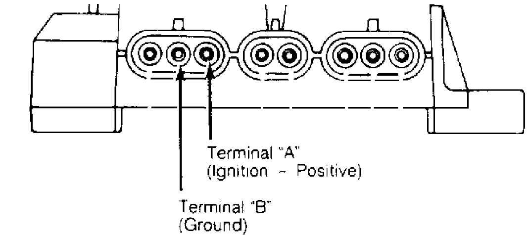
 Fig.
1: 2.5L TBI ICM Connector Terminals
Courtesy of American Motors/Jeep Corp.
Fig.
1: 2.5L TBI ICM Connector Terminals
Courtesy of American Motors/Jeep Corp.
OVERHAUL
NOTE: The 2.5L TBI distributor contains no electrical components other than the rotor and distributor cap. If any other distributor part is defective, the entire distributor assembly must be replaced.