FUEL INJECTION SYSTEM - TBI
1988 Jeep Cherokee
1988 Electronic Fuel Injection JEEP/RENIX THROTTLE BODY INJECTION
2 . 5L Cherokee, Comanche, Wagoneer, Wrangler
DESCRIPTION
The Throttle Body Injection (TBI) system is a single injector system that introduces fuel into throttle body from above throttle plate. Fuel injector, located within throttle body, is controlled by the Electronic Control Unit (ECU).
The ECU is a sealed microprocessor that receives input signals from several sensors and other related engine components. Based on these inputs, ECU generates output signals that control and adjust air/fuel mixture and ignition timing as necessary for proper engine performance.
ECU also controls engine idle speed, emission control
systems, upshift indicator light (manual transmission only), and A/C compressor clutch.
OPERATION
ELECTRONIC CONTROL UNIT (ECU)
On Cherokee, Comanche and Wagoneer, ECU is located under instrument panel, above accelerator pedal. On Wrangler, ECU is located behind glove box. Input information from various engine sensors to ECU is used to determine engine operating conditions and needs. Battery voltage input is used to ensure that correct output voltage is supplied by ECU during fluctuations in battery voltage.
FUEL INJECTOR
Fuel injector is mounted in throttle body so that fuel is injected into incoming airflow. When injector solenoid is energized, armature and plunger move upward against spring. Check ball above injector nozzle moves off seat and opens small orifice at end of injector.
Fuel supplied to injector is forced around ball and through orifice, resulting in fine spray of fuel. Volume of fuel injected is dependent only on length of time that injector is energized by ECU, as fuel pressure is constant at injector. During cold engine starts, extra fuel is supplied so richer mixture will aid in starting.
FUEL PRESSURE REGULATOR
Fuel pressure regulator is integral part of throttle body. Pressure regulator has a spring chamber that is vented to same pressure as tip of injector. Because differential pressure between injector nozzle and spring chamber is same, only the length of time that injector is energized controls volume of fuel injected.
Fuel pump delivers more fuel than is required by engine. Excess fuel goes to fuel tank from pressure regulator via fuel return hose. Fuel pressure regulator function is mechanical and ECU does not control it.
FUEL PUMP
Electric roller type fuel pump is located in fuel tank. Integral check valve is used to maintain pressure in fuel delivery system after pump stops running. Fuel pump operation is controlled by ECU through a fuel pump relay.
IDLE SPEED ACTUATOR (ISA) MOTOR
ISA motor acts as movable idle stop to change throttle stop angle. Both engine idle speed and deceleration throttle stop angle are set by ISA. ECU controls ISA motor by providing appropriate voltage outputs to produce idle speed or throttle stop angle required for engine operating condition.
OXYGEN (O2) SENSOR
Oxygen sensor is equipped with a heating element that keeps sensor at proper operating temperature at all times. Oxygen sensor is located in exhaust pipe.
Maintaining proper sensor temperature at all times, system enters "Closed Loop" operation sooner and remains in "Closed Loop" during periods of extended idle. Electrical feed to oxygen sensor is through ignition switch.
The ECU receives sensor voltage signal which varies with oxygen content in exhaust gas. Signal is used by ECU as reference for setting air/fuel mixture ratio. ECU varies voltage to injector both to compensate for battery voltage fluctuations and to change duration of injector opening for control of air/fuel mixture.
MANIFOLD AIR/FUEL TEMPERATURE (MAT) SENSOR
MAT sensor provides a signal to ECU that changes depending upon temperature of air/fuel mixture in intake manifold. During high temperature conditions, ECU will compensate for changes in density of air.
MANIFOLD ABSOLUTE PRESSURE (MAP) SENSOR
MAP sensor measures absolute pressure in intake manifold. Both mixture density and ambient barometric pressure are supplied to ECU by MAP sensor. Sensor is mounted in middle of firewall in engine compartment. Sensor receives manifold pressure information through vacuum line from throttle body. See Fig. 1.
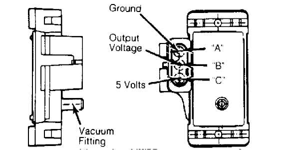
Fig. 1: Manifold Absolute Pressure (MAP) Sensor Courtesy of Chrysler Motors.
COOLANT TEMPERATURE SENSOR (CTS)
Coolant temperature sensor is installed in intake manifold water jacket to provide coolant temperature input signal for ECU. During cold engine operation, ECU will make mixture richer, make up for fuel condensation in cold intake manifold, increase idle speed during warm-up period, increase ignition advance and keep EGR system inoperative until engine warms up.
THROTTLE POSITION SENSOR (TPS)
Throttle position sensor provides ECU with input signal, up to about 5 volts, to indicate throttle position. This allows ECU to control air/fuel mixture according to throttle position. TPS is mounted on throttle body assembly.
WIDE OPEN THROTTLE (WOT) SWITCH
WOT switch provides an input signal to ECU when engine is at wide open throttle. The ECU enriches air/fuel mixture. The WOT switch is located on the side of throttle body.
CLOSED THROTTLE (IDLE) SWITCH
Idle switch is integral with ISA motor and provides voltage signal to ECU. ECU will signal ISA motor to change throttle stop angle in response to engine operating conditions.
UPSHIFT INDICATOR LIGHT
On vehicles equipped with a manual transmission, ECU controls upshift indicator light. Indicator light is normally illuminated when ignition is turned on without engine running. Indicator light is turned off when engine is started.
Indicator light will be illuminated during engine operation in response to engine load and speed. If transmission is not shifted, ECU will turn light off after 3 to 5 seconds. A switch located on transmission prevents indicator light from being illuminated when transmission is shifted to highest gear.
ENGINE SPEED SENSOR
Engine speed sensor is attached to bellhousing. It senses and counts teeth on flywheel gear ring as they pass during engine operation. Signal from speed sensor provides ECU with engine speed and crankshaft angle. On flywheel gear ring, large trigger tooth and notch is located 90 degrees before each TDC point. Each trigger tooth is followed by 12 smaller teeth and notches before TDC point is reached.
As each of 12 small teeth and notches pass magnetic core in speed sensor, concentration and collapse of magnetic field induces slight voltage (spike) in sensor pick-up coil winding. See Fig. 2. Larger trigger teeth and notches induce higher voltage (spike) in sensor pick-up coil winding. These voltage spikes enable ECU to count teeth as they pass speed sensor.
Higher voltage spike (from larger tooth and notch) indicates to ECU that piston will be at TDC position after 12 smaller voltage spikes have been counted. ECU will then either advance or retard ignition timing depending upon remaining sensor inputs.
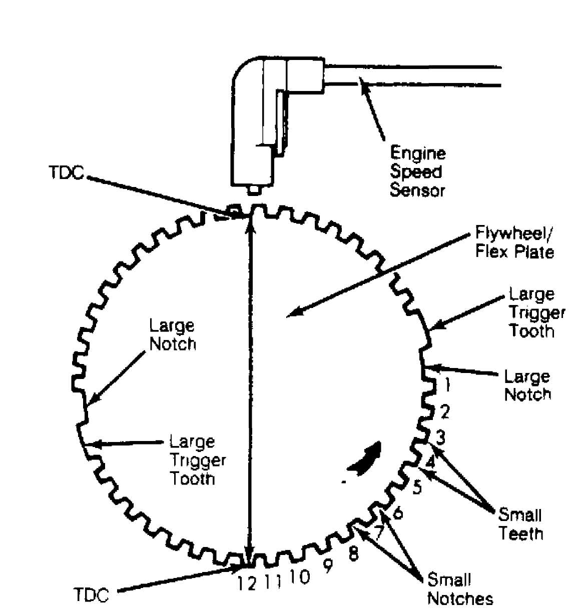
Fig. 2: Engine Speed Sensor Courtesy of Chrysler Motors.
A/C CONTROLS
ECU receives inputs from A/C when either A/C switch is in "ON" position or compressor clutch engages to lower temperature. ECU changes engine idle speed depending upon A/C compressor operation.
POWER STEERING PRESSURE SWITCH
ECU receives input from pressure switch during periods of high pump load and low engine RPM. Input signals from pressure switch to ECU are routed through A/C request and A/C select input circuits. When pump pressure exceeds 250-300 psi (17.5-21.0 kg/cm), switch contacts close transmitting an input signal to ECU. ECU raises engine idle speed immediately after receiving input from pressure switch.
RELAYS
Starter Motor Relay
Starter motor relay provides an input signal to ECU when starter motor is engaged.
System Power Relay
System power relay, located on right fender inner panel, is energized when engine is started. It remains energized for 3 to 5 seconds after ignition is off. This allows ECU to extend ISA for next start before ECU shuts down.
Fuel Pump Control Relay
Fuel pump control relay is located on right fender inner panel. Battery voltage is supplied to relay from ignition switch. When ground is provided by ECU, relay becomes energized and provides voltage to fuel pump.
A/C Compressor Clutch Relay
ECU controls A/C compressor clutch through this relay. The A/C compressor clutch relay is located beside fuel pump control relay on right fender inner panel.
EGR Valve/Canister Purge Solenoid
Vacuum to both EGR valve and vapor canister is controlled by this solenoid. When solenoid is energized, neither EGR valve nor vapor canister receive vacuum.
Solenoid is energized during closed (idle) and wide open throttle operations, engine warm-up and rapid acceleration or deceleration. If solenoid wire connector is disconnected, both EGR valve and vapor canister will receive vacuum at all times.
Load Swap Relay
The load swap relay works in conjunction with power steering switch to disengage A/C compressor clutch. If compressor clutch is engaged when power steering pressure switch contacts close, input signal from switch to ECU also activates load swap relay. Relay then cuts off current to A/C compressor clutch.
The A/C compressor clutch remains disengaged until pressure switch contacts reopen and engine idle returns to normal. The load swap relay contains a timer that delays engaging the compressor clutch for 0.5 second to ensure smooth engagement.
ADJUSTMENTS
CAUTION: When working on or near engine that is running, be very careful to avoid pulleys, belts and fan. DO NOT stand in direct line with blades of fan. DO NOT wear clothing that is loose enough to get caught in moving parts.
IDLE SPEED ACTUATOR (ISA) MOTOR
Adjust ISA
motor plunger to establish initial position of
plunger only if
motor has been removed or replaced. Remove air filter
elbow and
start engine. Run engine until engine reaches normal
operating
temperature. Turn A/C off (if equipped).
Connect
tachometer leads to diagnostic connector D1,
attaching
negative lead to terminal D1-3 and positive lead to
terminal
D1-1. See Fig. 4. Turn ignition off. ISA
motor plunger
should move to fully
extended position.
When
ISA motor plunger is fully extended, disconnect ISA
motor
wiring connector and start engine. Engine speed should be
3300-3700
RPM. If incorrect, turn hex head screw at end of
plunger to
provide engine speed of 3500 RPM.
Fully
retract ISA motor by holding closed throttle (idle)
switch
plunger inward as throttle is opened. Closed throttle switch
plunger
should not touch throttle lever in closed position. If
contact is
made, check linkage and/or cable for binding or damage.
Repair as
necessary.
Connect
ISA motor wiring harness connector and turn
ignition
off for 10 seconds. ISA motor should move
to fully extended
position. Start
engine. Engine speed should be 3500 RPM
for short
period of time and then decrease to normal idle speed.
Turn
ignition off. Disconnect tachometer. After final
adjustment
of ISA motor, use thread penetrating sealant (Loctite 290)
on
adjustment screw to prevent movement and maintain adjustment.
NOTE: If adjustment screw must be moved after thread sealant
hardens, loosen threads by heating screw with flameless heat such as soldering gun. DO NOT use flame or torch type of heat as damage to ISA motor will result.
FUEL PRESSURE REGULATOR
WARNING: Always relieve residual fuel pressure in fuel delivery
system before opening system. To prevent chance of personal injury, cover fittings with shop towel while disconnecting fittings.
1) Replacement
fuel pressure regulator must be adjusted to
establish
correct pressure. Remove air filter elbow and hose.
Connect
tachometer leads to diagnostic
connector D1, attaching negative lead
to terminal D1-3 and
positive lead to terminal D1-1. See Fig. 4.
Remove
screw plug and install fuel pressure test fitting.
NOTE: Fuel pressure test fitting is not included with throttle body. Fitting (8983 501 572) must be obtained separately.
Connect
fuel pressure gauge to test fitting. Start engine
and increase
speed to approximately 2000 RPM. Turn Torx
head screw at
bottom of regulator to
set correct pressure. Turning screw inward
increases
pressure and turning screw outward decreases pressure. See
Fig.
3.
All
models require fuel pressure of 14.5 psi
(1.0 kg/cm).
Install
lead sealing ball to cover regulator adjustment
screw after adjusting fuel pressure. Turn ignition off. Remove measuring equipment and test fitting. Install original plug screw and air filter assembly.
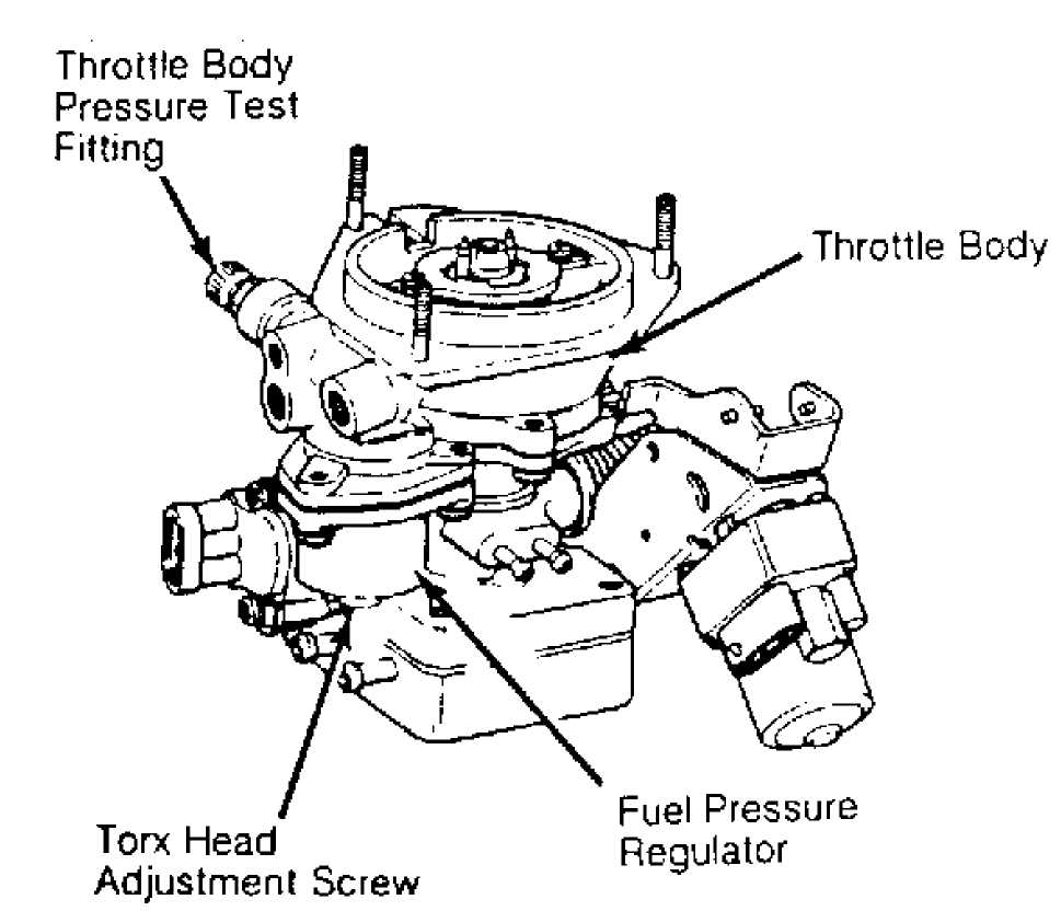
Fig. 3: Adjusting Fuel Pressure Regulator Courtesy of Chrysler Motors.
THROTTLE POSITION SENSOR (TPS)
1) Turn
ignition on. Check throttle position sensor input
voltage. Connect
voltmeter negative lead to terminal "B" (M/T),
or
terminal "D" (A/T) of sensor
connector. Connect voltmeter positive
lead
to terminal "C" (M/T), or
terminal "A" (A/T) of sensor connector.
NOTE: On (A/T) models, connector terminals are identified by
letters molded into back of connector. On all models, do not disconnect TPS harness connector. Insert voltmeter test leads through back of wire harness connector. On some models, it may be necessary to remove throttle body from intake manifold to gain access to sensor wire harness.
2) Move
and hold throttle plate at wide open throttle
position (M/T),
or close throttle plate completely (A/T).
Ensure
throttle
linkage contacts stop. Note voltmeter reading. Input voltage
at
terminals "B" and "C" (M/T), or
terminals "A" and "D" (A/T) should
be
5 volts.
Return
throttle plate to closed throttle position (M/T),
or
maintain throttle plate in closed position (A/T). Check
sensor
output voltage. To do so, disconnect voltmeter positive
lead from
terminal "C" and
connect it to terminal "A" (top) of sensor (M/T),
or
from terminal "A" and connect it
to terminal "B" (A/T).
Move and hold throttle plate in wide open throttle
position (M/T), or maintain throttle plate in closed position (A/T). Ensure throttle linkage contacts stop. Note voltmeter reading. Output voltage should be 4.6-4.7 volts (M/T), or .2 volt (A/T).
5) If
output voltage is incorrect, loosen bottom sensor
retaining screw
and pivot sensor in adjustment slot for a coarse
adjustment.
Loosen top sensor retaining screw for fine adjustments.
Tighten
screws after adjustment.
TESTING & TROUBLE SHOOTING
PRELIMINARY CHECKS & PRECAUTIONS
Subsystem Checks
Before testing fuel injection system for cause of
malfunction, check that following subsystems and components are in good operating condition:
Battery and charging system.
Engine state of tune.
Emission control devices.
Fuel system pressure and delivery volume.
Wiring connectors at components.
General Precautions
In order to prevent injury to operator or damage to system or component parts, use following techniques:
Turn
ignition off before connecting or disconnecting any
component
parts.
DO
NOT apply DC voltage greater than 12 volts
or any AC voltage
to system.
Disconnect battery cables before charging.
Remove
ECU from vehicle if ambient temperature could exceed
176F (80C).
DO NOT modify or circumvent any system functions.
RESISTANCE & VOLTAGE TESTS
MAT Sensor
Disconnect
wiring from MAT sensor. Using high input
impedance digital
volt-ohmmeter (DVOM), check resistance of
sensor.
Resistance should be less than 1000 ohms
when engine is warm. Replace
sensor if
it does not fall within range shown in
TEMPERATURE-TO-RESISTANCE
VALUES table.
Test
resistance in wiring harness between ECU connector
terminal No.
32 and sensor connector terminal. Also
test resistance
in wiring harness between ECU harness terminal
No. 14 and sensor
connector
terminal. See Fig. 5. Repair wiring
harness if open circuit
or resistance greater than one ohm is
indicated.
Coolant Temperature Sensor (CTS)
1) Disconnect wiring harness from CTS. Using high input impedance digital volt-ohmmeter (DVOM), check resistance of sensor. Resistance should be less than 1000 ohms when engine is warm. Replace sensor if it does not fall within range shown in TEMPERATURE-to-RESISTANCE VALUES table.
2) Test resistance in wiring harness between ECU harn terminal No. 32 and sensor connector terminal. Also test resistance in wiring harness between ECU harness terminal No. 15 and sensor connector terminal. See Fig. 5. Repair wiring harness if open circuit or resistance greater than one ohm is indicated.
TEMPERATURE-TO-RESISTANCE VALUES (CTS & MAT SENSOR) TABLE
 °F °C Ohms
(Approximate)
212 100 185
160 70 450
100 38 1600
70 20 3400
40 4 7500
20 -7 13,500
0 -18 25,000
-40 -40 100,700
Throttle Position Sensor (TPS) Test
Turn ignition on. Check voltage at terminal connector without disconnecting from TPS. Terminal "A" (M/T), or terminal "B" (A/T ) is output voltage, which should be 4.6-4.7 volts at wide open throttle (M/T), or .2 volt at closed throttle (A/T). Terminal "B" (M/T), or terminal "A" (A/T) is sensor ground. Terminal "C" (M/T), or terminal "D" (A/T) is input voltage, which is about 5 volts.
Closed Throttle (Idle) Switch Test
NOTE: ALL testing of idle switch must be done with ISA motor plunger in fully extended position. If switch cannot be tested without extending plunger, it is possible that ISA motor has failed. See IDLE SPEED ACTUATOR MOTOR ADJUSTMENT.
Turn
ignition on. Check idle switch voltage at diagnostic
connector
D2, between terminals No. 13 and 7.
See Fig. 4. At
closed
throttle, voltage should be near
zero volts. When switch is off
closed throttle position, voltage
reading should be greater than 2
volts.
If
voltage is always zero, test for short to ground in
harness or
switch. Also check for open circuit between switch and
terminal
No. 25 of ECU connector. If reading is
always greater than 2
volts, check for
open circuit in wiring harness between switch
connector and ECU.
Also check for open between ground and switch
connector. Replace
or repair wiring harness as necessary.
Manifold Absolute Pressure (MAP) Sensor Test
Check
and repair vacuum hose connections at throttle body
and MAP
sensor. Check output voltage at MAP sensor connector terminal
"B"
(marked on sensor body) with ignition on, engine off.
Voltage
reading should be 4-5 volts. If
engine is hot and idling in Neutral,
reading should be 1.5-2.1
volts. Check voltage at terminal No. 33
of
ECU connector. Reading should be same as
that at terminal "B" on MAP
sensor
connector. See Fig. 4.
With
ignition on, check MAP sensor supply voltage at
terminal "C".
Reading should be 4.5-5.5 volts. Same
voltage reading
should be obtained at terminal No. 16 on
ECU harness connector. If
necessary,
repair or replace wiring harness. Using Diagnostic Tester
(MS 1700), test ECU if necessary. Check MAP sensor ground circuit at terminal "A" and terminal No. 17 of ECU connector. Repair wiring if necessary.
3) Using ohmmeter, check MAP sensor ground circuit between terminals No. 17 and 2 of ECU connector. If circuit is incomplete, check sensor ground connection on bellhousing, near starter motor. Replace ECU if ground is good. If terminal No. 17 is shorted to 12 volts, repair problem BEFORE ECU is replaced.
DIAGNOSTIC TOOLS
To properly test throttle body fuel injection system, service technician must have the following equipment available:
Digital
volt-ohmmeter (DVOM) or volt-ohmmeter with minimum input
impedance
of one megohm.
12-volt test light, jumper wires and probes.
Hand vacuum pump with gauge.
Ignition timing light.
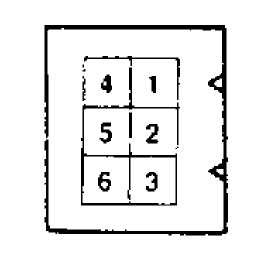
CONNECTOR D1
1.Tach{RPM) Input
Ignition
Ground
Starter Solenoid
Battery
Fuel Pump
CONNECTOR D2
1. Upshift Light (M/T)
2, System
Power Relay
3- Park/Neutral Switch
System Power {Bait. Pos.)
A/C Clutch Relay
WOT Switch
Ground
Air/Fuel Temperature
M.P.A. (Ignition Output)
EGR/Canister Purge Solenoid
ISA Motor Extend {Forward)
Coolant
Temperature Sensor
13- Closed Throttle
Switch
ISA Motor Reverse
Automatic Transmission Diagnosis
Fig. 4: Jeep/Renix Fuel Injection Diagnostic Connectors Courtesy of Chrysler Motors.
DIAGNOSTIC TESTS
NOTE: When diagnosing fuel system problems using following
procedures, no specialized service equipment is needed. Following diagnostic procedures are NOT applicable if special tester M.S. 1700 is used.
Six different test flow charts are used to fully evaluate fuel injection system:
TEST 1: IGNITION OFF
This test checks that system power provides for ECU memory keep-alive voltage.
function.
TEST 2: IGNITION ON: POWER
This test checks system power function and fuel pump power
TEST 3 & 3A: IGNITION ON: INPUT
These tests check the following components and their circuits: closed throttle (idle) switch, Throttle Position Sensor (TPS), MAP sensor, A/T gear selector switch, Coolant Temperature Sensor (CTS) and MAT sensor. Coolant temperature and MAT sensors are tested in cold condition. This procedure also checks all interrelated wiring circuits as well.
TEST 4 & TEST 4A: SYSTEM OPERATIONAL
These tests check engine start-up circuit, fuel injector, "Closed Loop" air/fuel mixture function, coolant temperature sensor function, MAT sensor function, detonation sensor "Closed Loop" ignition retard/advance function, EGR valve and canister purge solenoid function, idle speed control and A/C control functions.
TEST 5: BASIC ENGINE
This test indicates failures in related engine components that are not part of fuel injection system.
TEST 6: MANUAL TRANSMISSION UPSHIFT
This test checks upshift indicator light function on vehicles with manual transmissions.
Ground
Ground
Ignition Switch
Battery
EGR Valve/Canister Purge
Fuel Pump Relay
System
Power Relay
: 8- WOT Switch
9. Not Used
System Ground
Speed Sensor
Park/Neutral Switch (A/T)
TPS
(Ground)
14 MAT Sensor
15. Coolant Temperature Sensor
16, MAP
Sensor (Supply Voltage)
17 MAP Sensof
(Ground)
IB Upshift Light (M/T)
19, System Power (Batt Pos.)
20. Not
Used
21 Injector
A/C Compressor Clutch
ISA Motor Retract (Reverse)
ISA
Motor Extend (Forward)
25 Closed
Throttle (idle) Switch
Not Used
ignition Interference
Speed Sensor
Start Signal
A/C Select
Thmitle Position Sensor
Temperature Sensor Ground
MAP Sensor (Output Voltage)
A/C Request
Oxygen 0, Sensor Input
Fig. 5: Jeep/Renix Fuel Injection ECU Connector Courtesy of Chrysler Motors.
REMOVAL & INSTALLATION
COOLANT TEMPERATURE SENSOR (CTS)
Removal & Installation
Allow engine to cool down. Disconnect CTS wiring harness. Remove CTS from intake manifold and rapidly plug hole to prevent coolant loss. Install replacement CTS and connect CTS wiring harness.
FUEL INJECTOR
WARNING: Always relieve residual fuel pressure in fuel delivery
system before opening system. To prevent chance of personal injury, cover fittings with shop towel while disconnecting fittings.
Removal
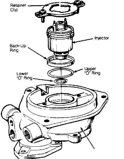
Remove air cleaner assemby. Remove injector wiring connector. Remove injector retainer screws and clip. Using small pliers, carefully grasp center collar of injector between electrical terminals and carefully remove injector with lifting/twisting motion. Discard both "O" rings. See Fig. 6.
Installation
Using
light oil, lubricate new upper and lower "O"
rings.
Install "O"
rings in housing bore. Install back-up ring over
upper
"O" ring. Position
replacement injector in fuel body.
Center nozzle in lower housing bore and use a
pushing/twisting motion to seat injector. Align wire connectors in proper orientation. Install retainer clip and screws. Connect injector wiring. Install air cleaner.
Throttle
Body
Fig. 6: Fuel Injector & Throttle Body Assembly Courtesy of Chrysler Motors.
FUEL PRESSURE REGULATOR
Removal & Installation
WARNING: Always relieve residual fuel pressure in fuel delivery
system before opening system. To prevent chance of personal injury, cover fittings with shop towel while disconnecting fittings.
With throttle body assembly removed, remove 3 screws holding fuel pressure regulator in throttle body. Remove fuel pressure regulator assembly. Note location of components for installation. Discard gaskets. To install, reverse removal procedure. Adjust regulator after installation. See ADJUSTMENTS in this article.
IDLE SPEED ACTUATOR (ISA) MOTOR
Removal & Installation
Disconnect
throttle return spring. Disconnect wiring
harness connector from
ISA motor. Remove ISA motor retaining nuts and
remove ISA motor
from bracket.
To install
ISA motor assembly, reverse removal procedure.
Adjust ISA motor
after installation. See ADJUSTMENTS in this article.
THROTTLE BODY ASSEMBLY
Removal
Remove air
inlet duct and adapter plate. Remove throttle
cable and return
spring. Disconnect electrical leads from fuel
injector, WOT
switch, and ISA motor.
Disconnect
fuel supply and return lines at throttle body.
See
Fig. 7. Tag and disconnect vacuum hoses.
Disconnect TPS wiring.
Remove throttle body assembly. If throttle
body assembly is being
replaced, transfer ISA motor and WOT
switch bracket assembly to new
unit.
Installation

Fig. 7: Intake Manifold & Throttle Body Assembly Courtesy of Chrysler Motors.
THROTTLE POSITION SENSOR
Install replacement throttle body assembly on manifold using new gasket. Reconnect all hoses, wires and cable in reverse order of disassembly. Adjust ISA motor after installation. See ADJUSTMENTS in this article.
Removal & Installation
Remove throttle body assembly as previously described. Remove Torx head retaining screws. Remove throttle position sensor from throttle shaft lever. To install, reverse removal procedure. Adjust TPS after installation. See ADJUSTMENTS in this article.
MANIFOLD AIR/FUEL TEMPERATURE (MAT) SENSOR
Removal & Installation
Disconnect wire harness connector from MAT sensor. Remove MAT sensor from intake manifold. To install, reverse removal procedure. See Fig. 7.
MANIFOLD ABSOLUTE PRESSURE (MAP) SENSOR
Removal & Installation
Disconnect wire harness connector, vacuum hose, and retaining nuts from MAP sensor. Remove sensor from firewall. To install, reverse removal procedure.
ELECTRONIC CONTROL UNIT (ECU)
Removal & Installation
On
Wrangler, remove passenger assist handle and glove box
assembly.
Remove ECU bracket retaining nuts from engine compartment
side of
firewall. Disconnect ECU wiring harness. Remove ECU from
bracket.
To install, reverse removal procedure.
On all
other models, remove retaining screws and bracket
that supports
ECU above accelerator pedal. Remove ECU and disconnect
wiring
harness. To install, reverse removal procedure.
EGR VALVE
Removal & Installation
Disconnect vacuum hose from EGR valve. Remove bolts which hold EGR valve to intake manifold. Remove valve and discard gasket. To install valve, reverse removal procedure. Always use new gasket. See Fig. 7.
TROUBLESHOOTING AND DIAGNOSIS
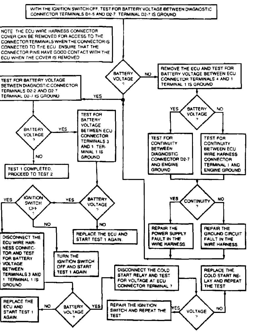 Fig.
Fig.
36961
: TEST 1:
TEST1: IGNITION OFF
I
IGNITION OFF
TEST 2: IGNITION ON: POWER

Fig. 9:
36962
TEST 2:
CONTINUED ON NEXT GRAPHIC
IGNITION ON: POWER
CONTINUED FROM PREVIOUS GRAPHIC
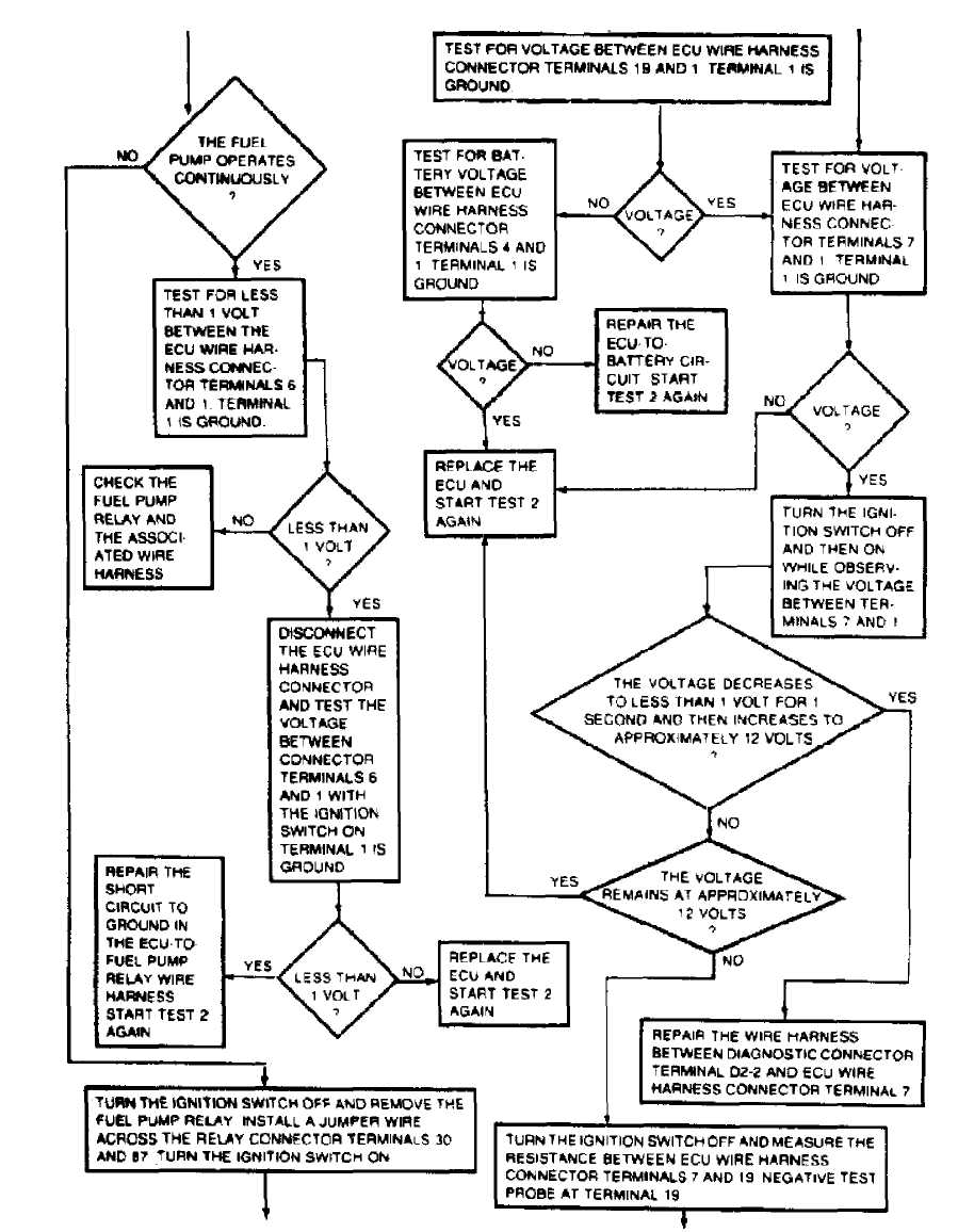
Fig.
36963
10: TEST 2:
IGNITION ON: POWER (Cont.)
TEST 3: IGNITION ON: INPUT
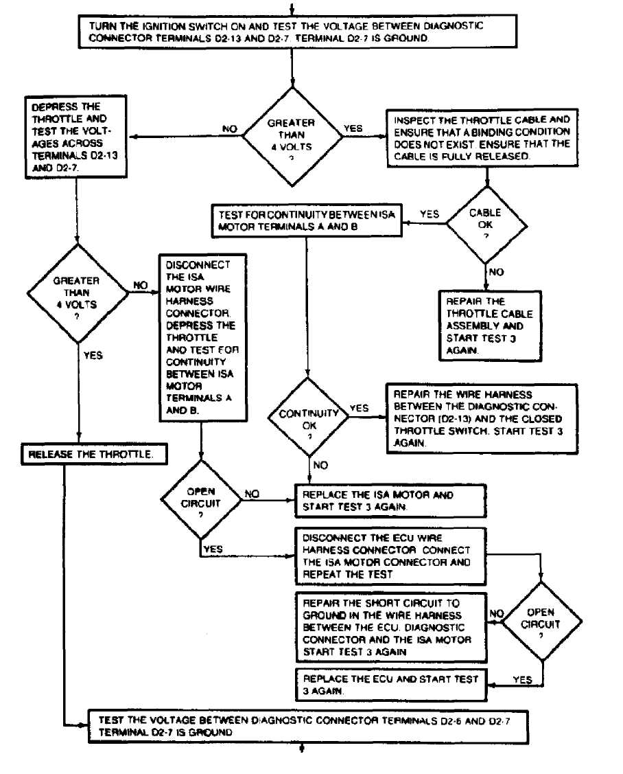 Fig.
11:
Fig.
11:
36965
TEST 3:
CONTtNUED ON NEXT GRAPHIC
IGNITION ON: INPUT
CONTINUED FROM PREVIOUS GRAPHIC
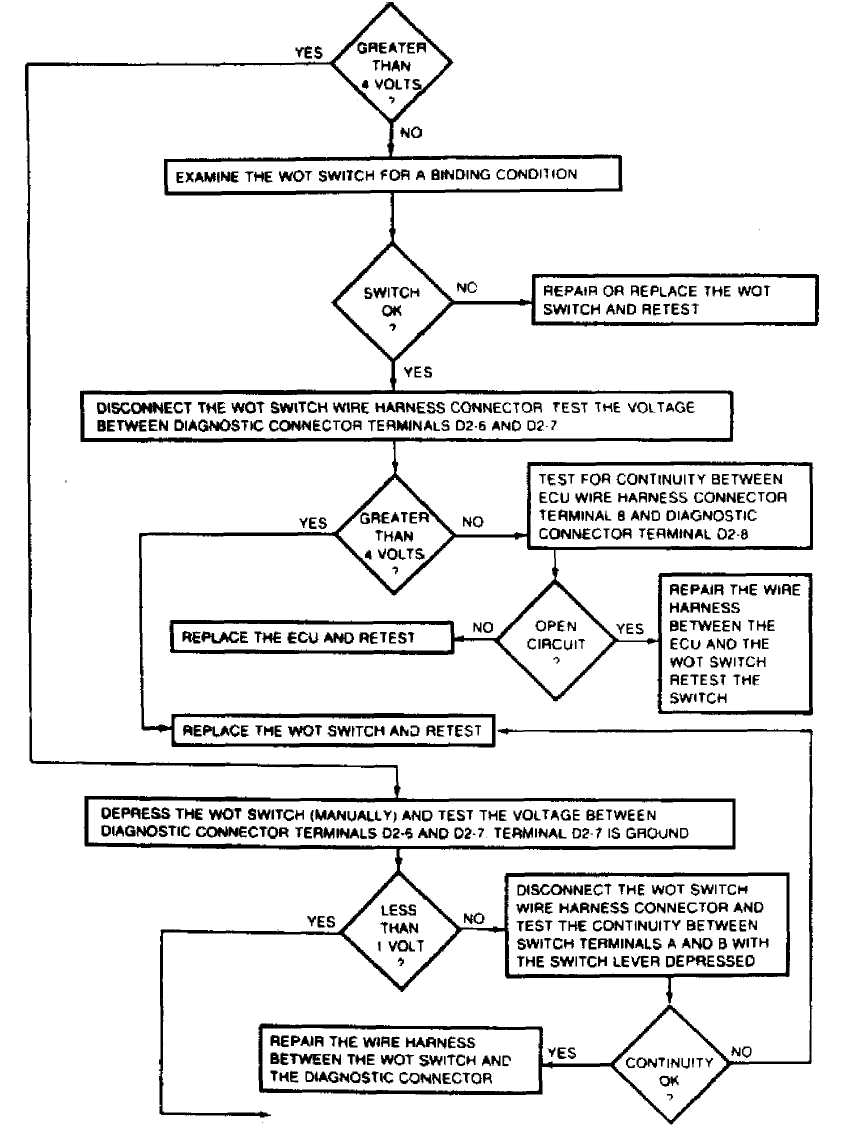 Fig.
Fig.
36966
12: TEST
3: IGNITION ON: INPUT (Cont.)
TEST 3: IGNITION ON: INPUT (Cont.)
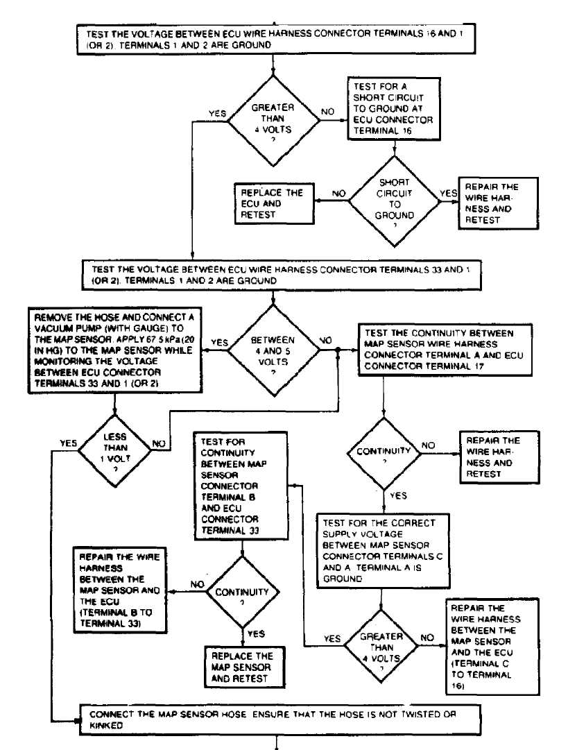
I
CONTINUED ON NEXT GRAPHIC
36967
Fig. 13: TEST 3: IGNITION ON: INPUT (Cont.)
TEST ÇŔ: IGNITION ON: THROTTLE POSITION SENSOR
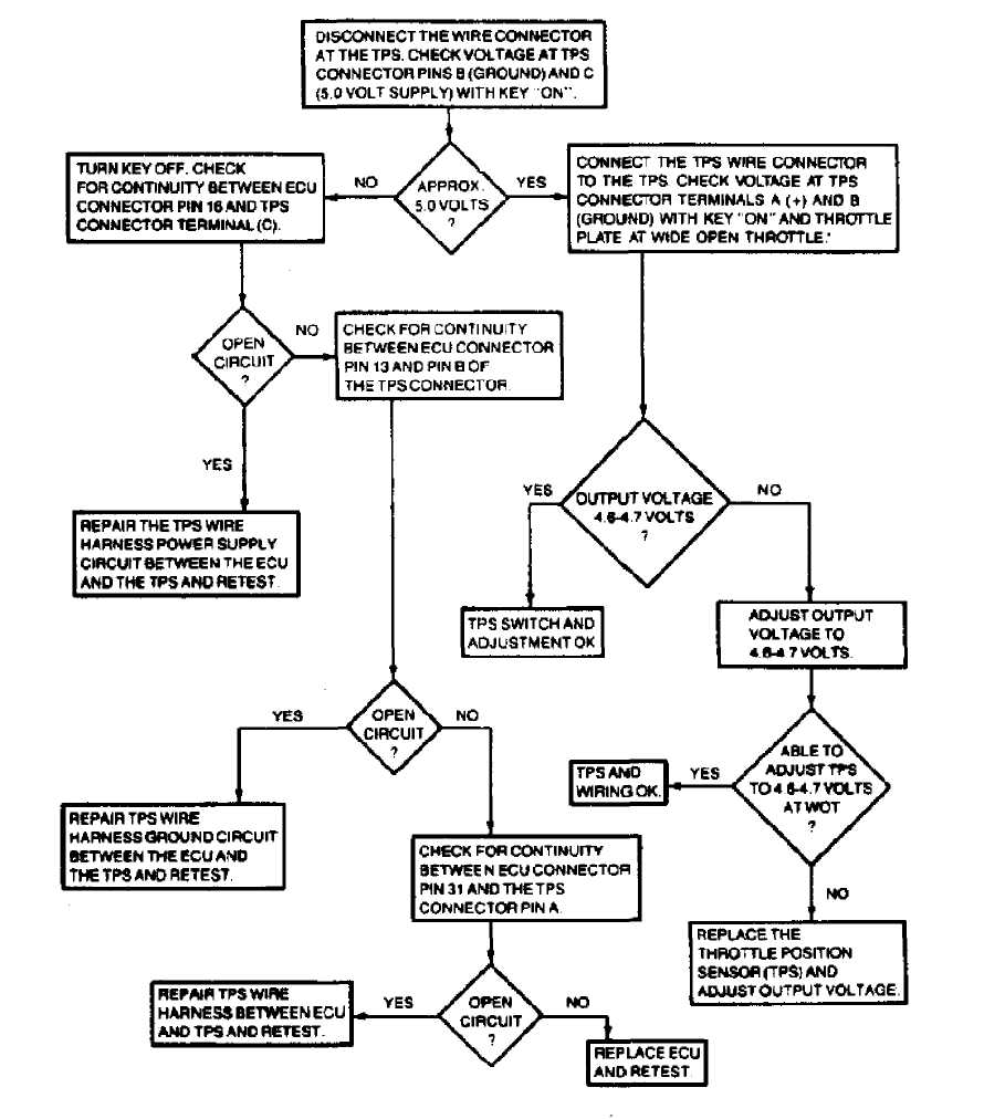
• DO MOT UNFASTEN THE SENSOR WIRE HARNESS CONNECTOR INSERT THE VOLTMETER TEST LEADS THAOUOH THE BACK OFTHE WIRE HARNESS CONNECTOR TQMAKE CONTACT WITH THE SENSOR TERMtNALS. ON SOME MODELS, IT MAY ALSO BE NECESSARY TO REMOVE THE THROTTLE BODY FROM THE INTAKE MANIFOLD. TO QAIN ACCESS TO THE SENSOR WIRE HARNESS CONNECTOR.
36971
Fig. 14: TEST 3A: IGNITION ON: THROTTLE POSITION SENSOR (M/T)
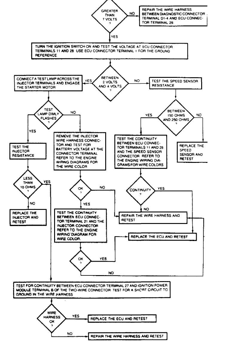
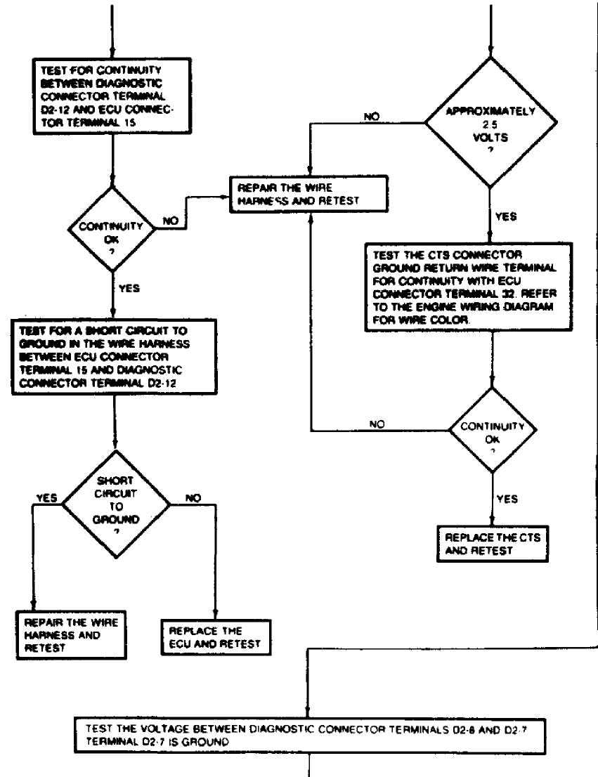
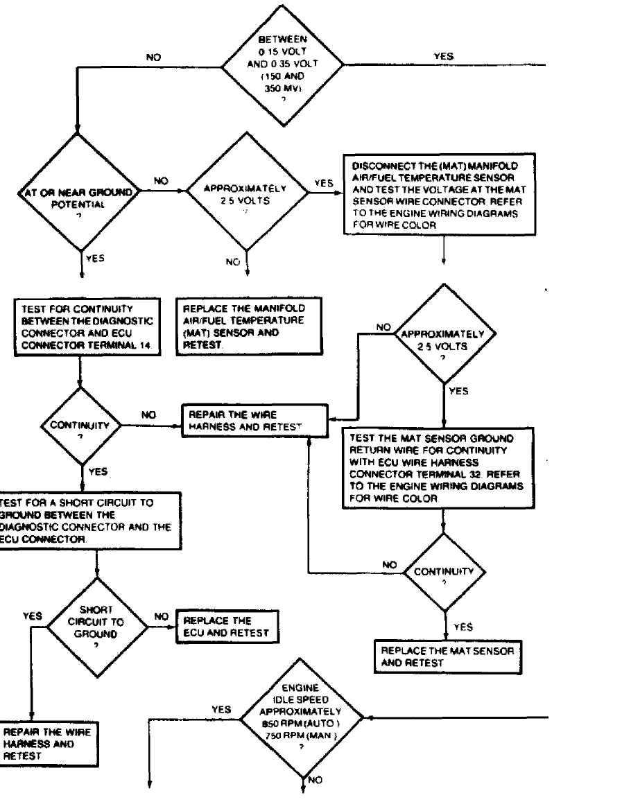
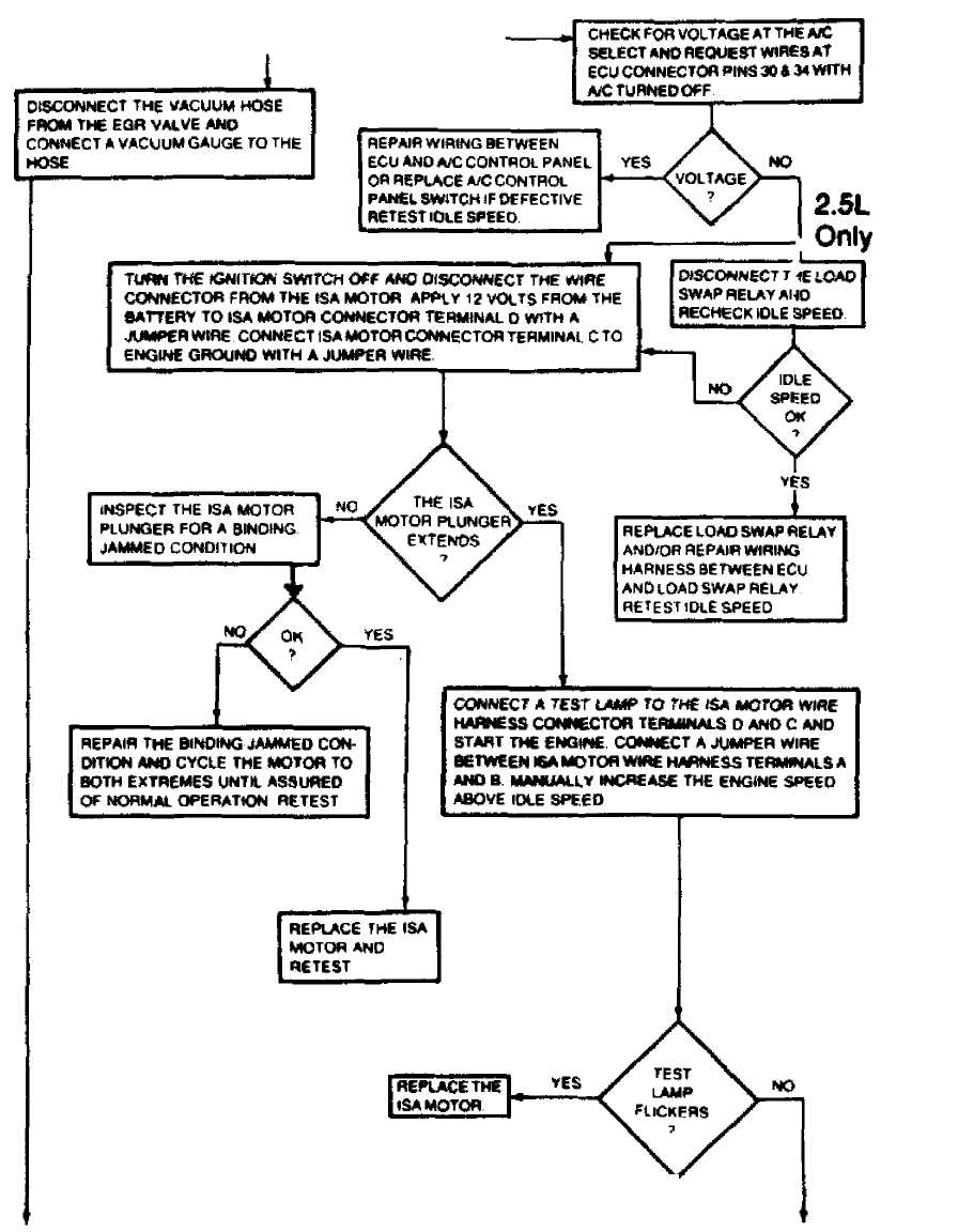
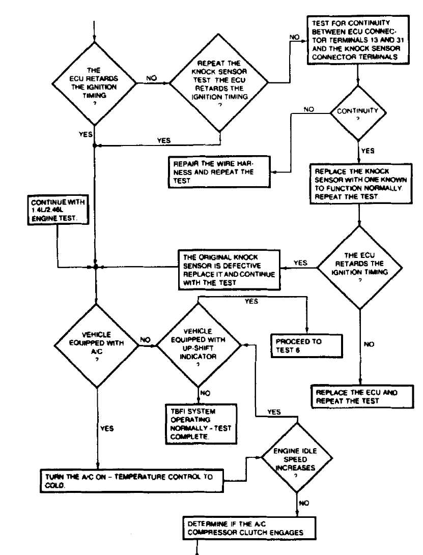
TEST 4: SYSTEM OPERATIONAL (Cont.)
36973
Fig. 15: TEST 4: SYSTEM OPERATIONAL
TEST 4A: SYSTEM OPERATIONAL

CONTINUED ON NEXT GRAPHIC
36974
Fig. 16: TEST 4: SYSTEM OPERATIONAL (Cont.)
 CONTINUED
FROM PREVIOUS GRAPHIC
CONTINUED
FROM PREVIOUS GRAPHIC
CONTINUED ON NEXT GRAPHIC 36975
Fig. 17: TEST 4A: SYSTEM OPERATIONAL
CONTINUED FROM PREVIOUS GRAPHIC
36976
Fig. 18: TEST 4A: SYSTEM OPERATIONAL (Cont.)
CONTINUED FROM PREVIOUS GRAPHIC
CONTINUED ON NEXT GRAPHIC
36977
Fig. 19: TEST 4A: SYSTEM OPERATIONAL (Cont.)
CONTINUED FROM PREVIOUS GRAPHIC
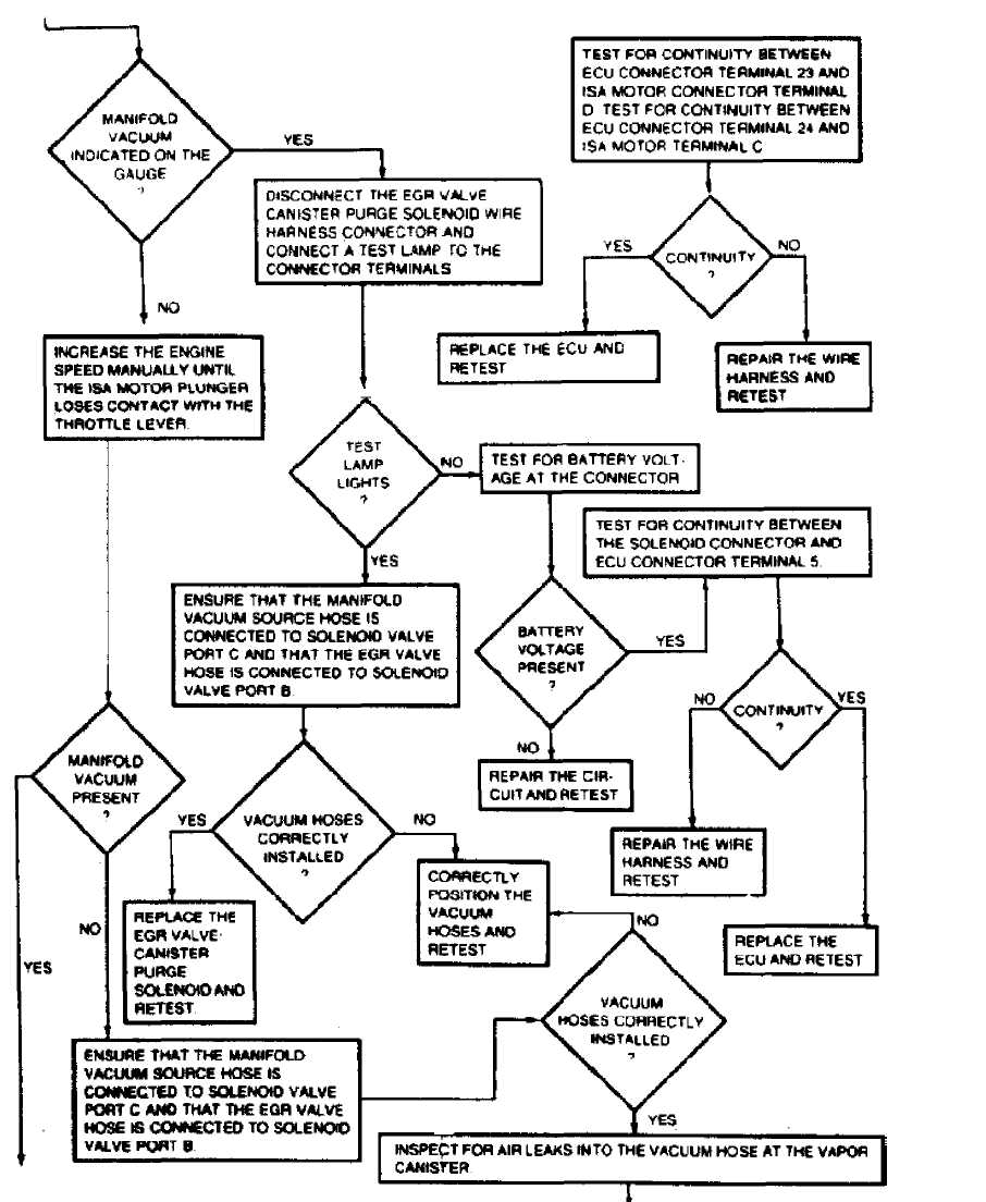
CONTINUED ON NEXT GRAPHIC 36978
Fig. 20: TEST 4A: SYSTEM OPERATIONAL (Cont.)
CONTINUED FROM PREVIOUS GRAPHIC
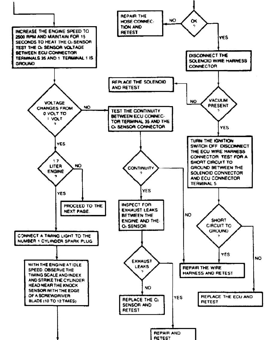
 Fig.
21:
Fig.
21:
36979
TEST 4A:
SYSTEM OPERATIONAL (Cont.)
TEST 4A: SYSTEM OPERATIONAL (Cont.)
CONTINUED ON NEXT GRAPHIC
36980
Fig. 22: TEST 4A: SYSTEM OPERATIONAL (Cont.)
TEST 5: BASIC ENGINE
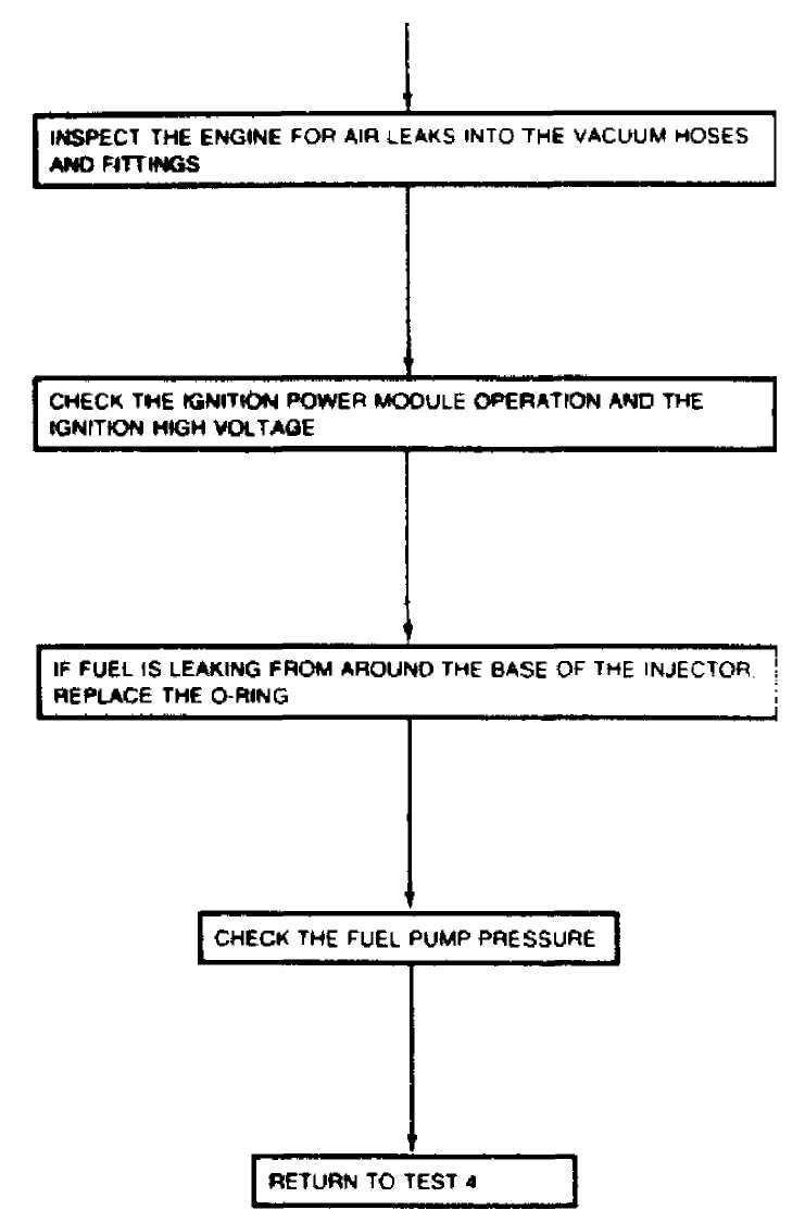
36983
Fig. 23: TEST 5: BASIC ENGINE
TEST 6: MANUAL TRANSMISSION UP-SHI FT
i
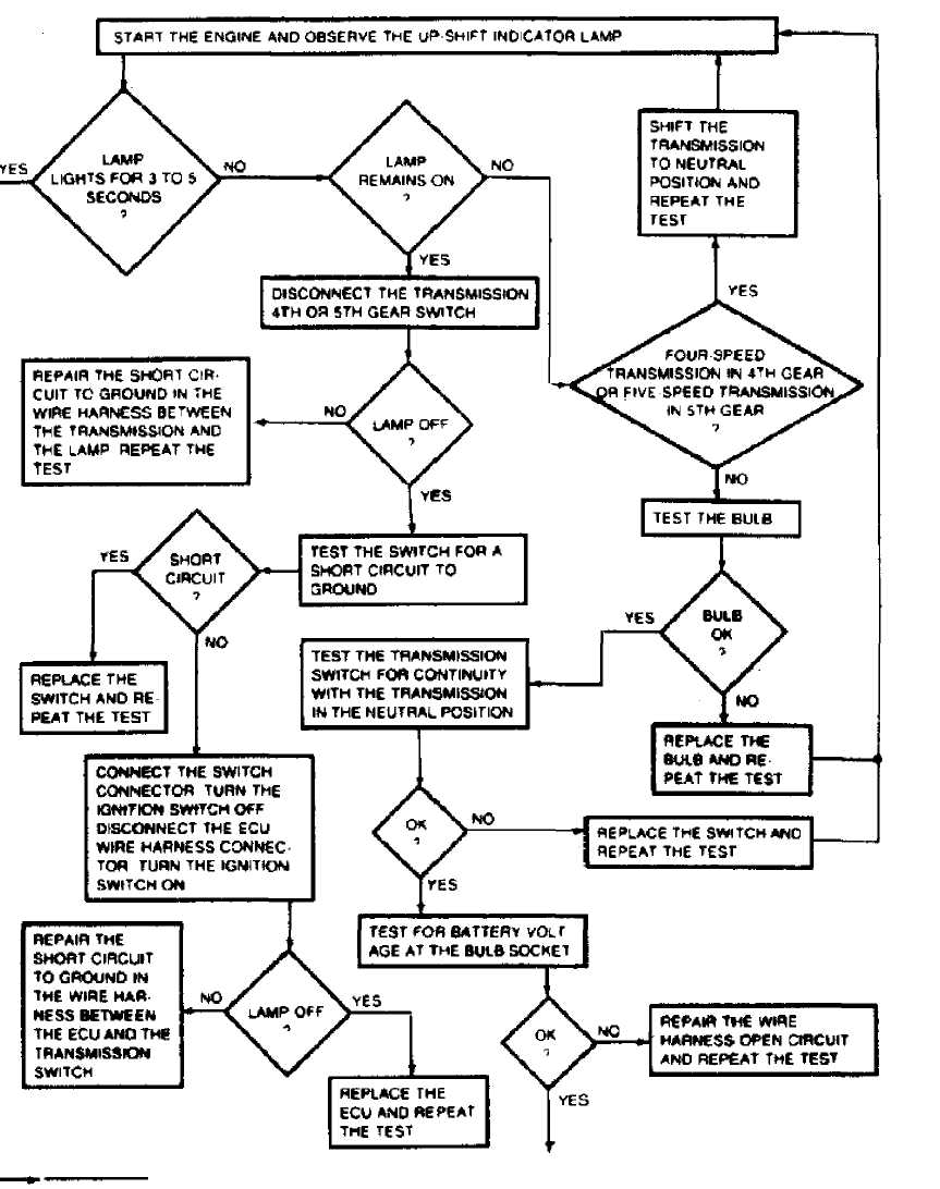
Fig. 24:
CONTINUED ON NEXT GRAPHIC
TEST 6: MANUAL TRANSMISSION UPSHIFT
WIRING DIAGRAMS
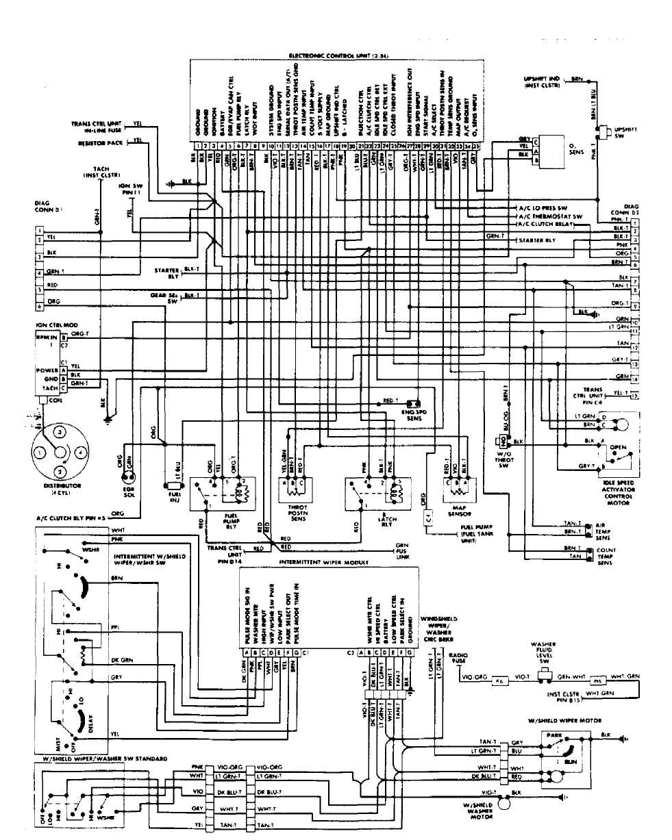
 Fig.
25: Cherokee, Comanche &
Wagoneer Throttle Body Fuel Injection
System Wiring Diagram
Fig.
25: Cherokee, Comanche &
Wagoneer Throttle Body Fuel Injection
System Wiring Diagram
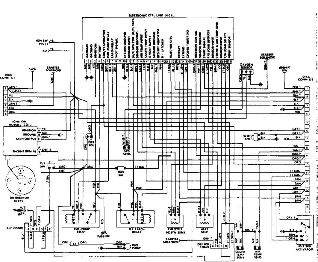
Fig. 26: Wrangler Throttle Body Fuel Injection System Wiring Diagram