DRIVE AXLE - STANDARD
1988 Jeep Cherokee
1988 DRIVE AXLES
Jeep 7 9/16" & 8 7/8" Ring Gear
All Models
DESCRIPTION
The rear axle assembly is a hypoid gear type with integral carrier housing. The standard axle uses a 7 9/16" (192 mm) diameter ring gear. The heavy duty axle uses an 8 7/8" (225 mm) diameter ring gear. See Fig. 1.
IDENTIFICATION
Axle assembly has 10-bolt rear cover. The axle ratio and ring and pinion gear tooth combinations are stamped on a tag attached to differential housing cover.
AXLE RATIO IDENTIFICATION
Axle Ratio Tooth Combinations Ring Gear Diameter
3.31:1 ................. 13/43 ............. 7 9/16" (192 mm)
3.54:1 ................. 13/46 ............. 7 9/16" (192 mm)
4.11:1 ................. 9/37 .............. 7 9/16" (192 mm)
4.10:1 ................. 10/41 .............. 8 7/8" (225 mm)
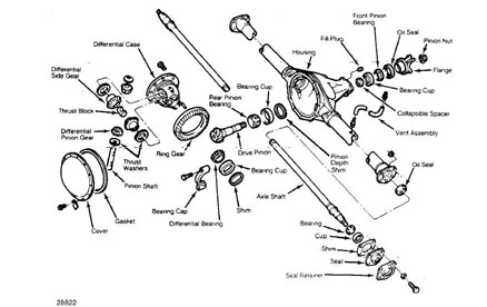
Fig. 1: Exploded View of Rear Axle Assembly
REMOVAL & INSTALLATION
AXLE SHAFTS & BEARINGS
Raise and support vehicle. Remove rear wheel and brake
drum. Remove axle shaft retaining nuts. Remove axle shaft from axle
tube and mount in vise. Drill a 1/4" hole 3/4 of the way through
retaining ring. Use care not to drill into axle shaft.
Cut the ring with a chisel and remove it from the shaft.
Remove bearing from axle shaft using arbor press. Remove axle seal.
See Fig. 2.
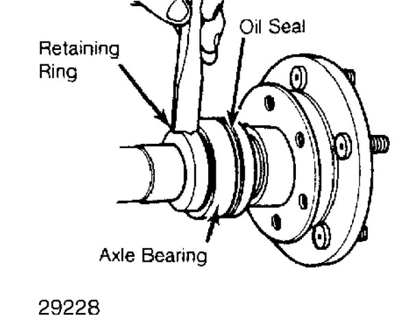
Fig. 2: Removing Axle Bearing Retaining Ring
Installation
Pack wheel bearing with grease. Coat inner axle shaft seal
with axle grease and outer portion of seal with gasket sealant.
Ensure components are correctly placed upon axle. Using
Bearing Installer (J-22912-01), press axle shaft bearing and new
retainer ring on axle shaft. Ensure bearing and retainer ring are
seated against axle shaft shoulder. Apply a thin coat of bearing
lubricant to axle flange bearing bore and install axle. YOKE& PINION OIL SEAL
Removal
Raise and support vehicle. Remove wheels and brake drums.
Mark and remove drive shaft. Using an INCH lb. torque wrench, record
torque required to rotate pinion several revolutions.
Hold yoke from turning and remove pinion nut. Mark drive
pinion shaft and yoke for reassembly reference. Remove yoke and pinion
oil seal.
Installation
1) Coat new seal with rear axle lubricant and install. Align
marks made at disassembly and install yoke. Install new pinion nut and
tighten just enough to remove end play.
CAUTION: DO NOT overtighten pinion nut. If desired preload is
exceeded, a new collapsible pinion spacer sleeve must be installed and drive pinion preload reset.
2) Using an INCH lb. torque wrench, check torque required to
turn pinion. Refer to torque reading recorded during disassembly and
add 5 INCH lbs. (.6 N.m) for correct preload. Tighten pinion nut
slightly and recheck preload. Repeat procedure until desired preload
is obtained.
REAR AXLE ASSEMBLY
Removal
Raise and support vehicle. Remove wheels and brake drums.
Disconnect brake hose-to-axle connection and plug line.
Disconnect parking brake cable at brake equalizer. Mark
and remove drive shaft. Disconnect track bar at axle bracket (if
equipped). Remove axle vent tube at axle. Support axle assembly.
Remove spring "U" bolts and tie plates.
Loosen, but do not remove, bolts which attach front of
rear spring to frame brackets. Lift axle to relieve axle weight from
springs and remove bolts retaining springs to shackles. Lower springs
to floor. Lower jack and remove axle assembly.
NOTE: Factory axles are shipped without lubricant. When adding lubricant, position axle horizontally with yoke end of pinion housing facing downward. Turn pinion shaft several times to lubricate bearings.
Installation
To install, support axle assembly with jack and slide axle
into place. Raise, align and install spring-to-frame and shackle
bolts. Tighten spring-to-frame and shackle bolts to 111 ft. lbs. (150
N.m). Install brake hose, axle vent tube and parking brake cable.
Align and connect drive shaft.
Bleed hydraulic system and adjust parking brake cable.
Ensure axle is filled with 75-90W gear lubricant. Ensure spring
centering bolt heads are seated in axle spring seat before tightening
"U" bolts.
OVERHAUL
DISASSEMBLY
NOTE: It is not necessary to remove axle assembly from vehicle to
perform overhaul.
Raise and support rear of vehicle. Remove rear cover and
drain lubricant. Remove wheels, brake drums, hubs and axle shafts.
Mark differential bearing caps for reassembly reference
and loosen them until a few threads remain engaged. Pry differential
loose and remove bearing caps and differential from housing.
Mark bearing caps, races and shims for reassembly
reference. Remove differential side bearings with a puller. Remove
differential and ring gear from case. Remove pinion shaft lock pin.
Using 2 feeler gauges, measure differential side gear
clearance. Insert an equal distance feeler gauge between each side
gear and case. Continue checking clearance until each feeler gauge is
a tight drag fit. Ensure side clearance does not exceed .007" (.18 mm)
on either side. If side gear clearance exceeds specification, replace
side gear thrust washers.
Remove pinion yoke and nut. Retain pinion nut for pinion
depth adjustment during reassembly. Tap pinion gear end with a soft
faced mallet to release it from front bearing. Remove pinion gear,
pinion bearings and preload collapsible spacer. Discard collapsible
spacer.
Remove pinion seal and pinion rear bearing cup. Remove and
retain pinion depth shim located under rear bearing cup. Remove pinion
front bearing cup. Using a press, remove pinion gear rear bearing.
CLEANING & INSPECTION
Clean all components in solvent and dry with compressed air. Inspect all components for excessive wear or damage and replace as necessary.
REASSEMBLY
NOTE: Ensure correct shims have been chosen to obtain proper
ring gear backlash and bearing preload before reassembly. See ADJUSTMENTS in this article.
Drive Pinion
1) Press rear bearing on pinion stem with large diameter of
roller cage toward gear. Clean housing bearing bores. Place shim in
rear bearing bore and install rear bearing cup.
NOTE: When installing a new gear set, use original depth shim as a starting point. Chamfered side of shim must be installed to bottom side of rear bearing cup bore.
2) Install front bearing cup into housing. Install drive
pinion through rear bearing cup. Install front bearing, yoke and
original pinion nut. Tighten nut to remove bearing end play only.
NOTE: A new nut and collapsible spacer are not installed at this time, as pinion will be removed after a depth measurement.
Differential Case
Assemble side gears and thrust washers and install into
differential case. Ensure side gear thrust washers were replaced in
clearance measured at disassembly was greater than .007" (.18 mm).
Install differential pinions and thrust washers in case.
Ensure pinions are aligned with shaft bores. Recheck side gear
clearance. If clearance exceeds .007" (.18 mm), side gears must be
replaced.
Install differential pinion shaft and lockpin. Using
Remover (J-22912-01), remove differential bearings. Install correct
size end play shims on each side of differential case. Position and install ring gear on differential case. Install replacement ring gear bolts and tighten standard axle ring gear bolts to 70-90 ft. lbs.
(95-122 N.m) . Tighten heavy duty drive axle bolts to 105 ft. lbs.
(142 N.m).
4) Check ring gear backlash. See RING GEAR BACKLASH in
ADJUSTMENTS. Lightly lubricate differential bearings, cups, gears and thrust washers with axle lubricant. Install bearing cups on differential bearings. Install differential in axle housing.
Using a soft faced hammer, tap outer edges of differential
bearing cups to seat them in housing. Install differential bearings
caps and tighten cap bolts to 57 ft. lbs. (77 N.m).
Recheck and verify ring gear backlash has not changed.
Install axle housing cover. Tighten cover bolts to 14 ft. lbs. (19 N.
m). Refill axle with 75-90W gear lubricant.
ADJUSTMENTS
DRIVE PINION DEPTH
Check numbers painted on drive pinion and ring gear. First
number on pinion must match number on ring gear. Second number on
pinion is pinion depth variance. If number is preceded by a plus sign,
add that number to standard pinion depth. If number is preceded by a
minus sign, subtract that amount from standard pinion depth. This will
give desired pinion depth. Record this measurement for future
reference.
If numbers painted on drive gear and ring gear do not
match, gears are not a matched set and should not be used. Some
factory installed sets may have .01" (.25 mm) or .02" (.50 mm)
machined off pinion end face.
Identifying numbers will appear as "+23". Number "2"
indicates .02" (.50 mm) was removed from end face and number "3" is
pinion depth variance. If marked "+16", number "1" indicates .010"
(.25 mm) was removed from end face and number "6" is pinion depth variance.
4) Standard pinion depth on standard drive axle is 2.0 95"
(53.21 mm) . Standard pinion depth on heavy duty drive axle is 2.547"
(64 . 69 mm) .
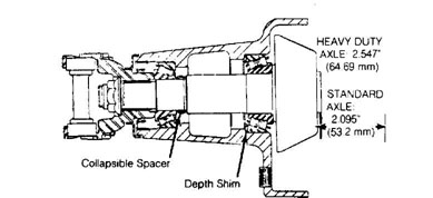
Fig. 3: Pinion Depth & Preload Shim Location
Standard Setting Dimension
5) Measure thickness of original pinion depth shim. Note pinion depth variance numbers marked on old and new pinion gears. Refer to PINION DEPTH SHIM ADJUSTMENT SPECIFICATIONS at end of this
article and determine amount to be added or subtracted from original shim thickness to obtain starter shim thickness. DO NOT use starter shim thickness as a final shim setting.
Install rear bearing on pinion gear. On heavy duty rear
axle, large end of bearing faces gear end of pinion. Press bearing
against rear face of gear.
On all axles, clean pinion bearing bores in axle housing
to ensure accurate measurement. Install and center starter shim in
housing bearing cup bore. If shim is chamfered, ensure chamfered side
faces bottom of bearing cup bore.
Install pinion rear and front bearing cups. Install pinion
gear in rear bearing cup and install pinion front bearing and yoke on
pinion gear. DO NOT install oil seal or collapsible spacer at this
time. Install and tighten original pinion nut only enough to remove
end play. Determine depth variance marked on pinion gear.
Install Arbor (J-5223-4) and Discs (J-5223-23) in
differential bearing cup bores. Ensure discs are fully seated in
bearing cup bores. Install bearing caps over discs and install bearing
cap bolts. Tighten bolts, but not to specified torque.
Position Gauge Block (J-5223-20) against end of drive
pinion with Clamp (J-5223-24) and Bolt (J-5223-29). See Fig. 4. Extend
clamp bolt until it presses against gauge block enough to prevent
gauge block from moving.
Loosen thumbscrew in end of gauge block to allow plunger
to contact arbor. When plunger contacts arbor, tighten thumbscrew,
taking care not to disturb plunger position.
Remove gauge block and measure distance from end of anvil
to top of plunger head, using a 2-3" (51-76 mm) micrometer. Record
this measured pinion depth for future reference.
Remove gauging tools, drive pinion and rear bearing cup.
Remove drive pinion depth shim and record thickness. Add shim
thickness to measured pinion depth. From this total subtract desired
pinion depth. For an example, see DETERMINING CORRECT SHIM THICKNESS
table.
DETERMINING CORRECT SHIM THICKNESSES
Application In. (mm)
Standard Drive Axle
Standard Pinion Depth .............................. 2.095 (53.21)
Pinion Depth Variance ............................... - .004 (.10)
Desired Pinion Depth .............................. =2.091 (53.11)
Measured Pinion Depth .............................. 2.100 (53.34)
Starting Shim Thickness ............................ + .096 (.096)
Total Measured Thickness Depth .................... =2.196 (55.77)
Total Measured Pinion Depth ........................ 2.196 (55.77)
Desired Pinion Depth .............................. -2.091 (53.11)
Correct Shim Thickness .............................. =.105 (2.66)
Heavy Duty Drive Axle
Standard Pinion Depth .............................. 2.547 (64.69)
Pinion Depth Variance ............................... + .007 (.18)
Desired Pinion Depth .............................. =2.554 (64.87)
Measured Pinion Depth .............................. 2.550 (64.77)
Starting Shim Thickness ............................. +.098 (2.49)
Total Measured Pinion Depth ....................... =2.648 (67.26)
Total Measured Pinion Depth ........................ 2.648 (67.26)
Desired Pinion Depth .............................. -2.554 (64.87)
Correct Shim Thickness .............................. =.094 (2.39)
14) The result represents correct shim thickness to be
installed. Install correct thickness shim in rear bearing bore and
install rear bearing cup. See Fig. 3.
NOTE: Replacement pinion gears marked more than .009" (.23 mm) should not be used.
See PINION DEPTH SHIM ADJUSTMENT SPECIFICATIONS to
determine appropriate starter shim thickness when installing NEW gear
sets. Note pinion variance numbers on new and old gear. Follow old
pinion marking line across to new pinion marking column.
The number in box indicates change in shim thickness from
original. For example, old pinion marked "-3" and new pinion marked
"+2". Intersecting box shows -.005" (.13 mm) to be subtracted from
original shim thickness.
Starter shim thickness must not be used as a final shim
setting. An actual pinion depth measurement must be made and final
shim thickness should be adjusted as necessary.
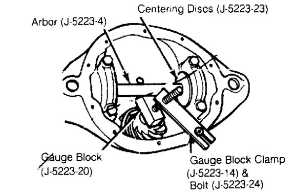
Fig. 4: Measuring Pinion Depth
DRIVE PINION BEARING PRELOAD
1) Install new collapsible spacer and front bearing on drive pinion. Install oil seal, yoke and nut. Tighten pinion nut only enough to remove bearing end play.
CAUTION: Never reuse collapsible spacer.
2) Slowly tighten pinion nut until torque required to rotate pinion gear is 15-25 INCH lbs. (2-3 N.m). Check torque frequently and only tighten nut in small amounts.
CAUTION: DO NOT overtighten pinion nut. If preload torque is
exceeded, collapsible spacer must be replaced and preload reset.
DIFFERENTIAL BEARING END PLAY
Place bearing cup over each differential bearing. Install
differential case assembly (without drive gear) in axle housing. On
standard drive axles, install a .142" (3.60 mm) shim on each side of
differential bearing cup and housing. On heavy duty drive axles,
install a .080" (2.03 mm) shim on each side of differential bearing
cup and housing.
Install bearing caps and tighten bolts finger tight. Mount
dial indicator to housing so indicator button touches ring gear face
of differential case. Prying between shims and housing, move assembly
to one side. Zero dial indicator, then pry assembly to opposite side.
Read and record indicator reading. DO NOT zero or read indicator while
prying.
Amount read on indicator is shim thickness which must be
added in order to arrive at a no preload or end play condition. Shims
are available in thicknesses of .142" (3.60 mm) to .174" (4.41 mm) in
.002" (.050 mm) increments.
When all side play is eliminated, check drive gear face of
case for runout. Runout should not exceed .002" (.050 mm) . Remove case
from housing and retain shims used to eliminate side play. See Fig. 5.
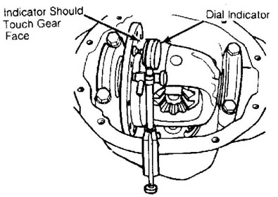
Fig. 5: Differential Bearing End Play & Runout Measurement
RING GEAR BACKLASH ADJUSTMENT
1) Install differential and ring gear assembly in housing
using shims selected to remove end play. Tighten bearing cap bolts evenly to 57 ft. lbs. (77 N.m) for standard drive axle and 85 ft. lbs.
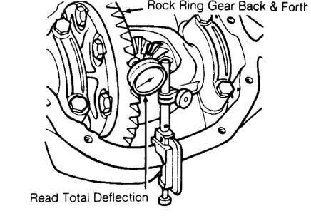
(115 N.m) for heavy duty drive axle. Attach a dial indicator to housing so button of indicator contacts drive side of a tooth of ring gear, at a right angle to tooth. See Fig. 6. Rock ring gear and note movement on dial indicator.
2) Backlash should be .005-.009" (.13-.23 mm) with .008"
(.20 mm) desired. To increase backlash, install thinner shim on ring gear side of case and a thicker shim on opposite side of case. To decrease backlash, reverse placement of shims. DO NOT change total shim thickness, alter positions only.
DIFFERENTIAL BEARING PRELOAD
Differential bearings are preloaded by increasing existing
shim thickness by .004" (.10 mm). Install differential bearing shims
in axle housing bearing bore. DO NOT distort shims by hammering them
into housing.
Assemble bearing cups on bearings (cups should completely
cover rollers). Position differential so bearings just start to enter
in axle housing bearing bores. Keep assembly square in housing and
push in as far as possible.
Using a soft hammer, tap outer edge of bearing cups until
seated in housing. Install bearing caps, aligning marks made at
disassembly. Install and tighten bolts. Preloading differential
bearings may change backlash setting so recheck backlash and correct
as necessary.
29232
Fig. 6: Checking Ring Gear Backlash
4) After all adjustments, check gear tooth pattern. See the GEAR TOOTH CONTACT PATTERNS article in this section.
AXLE ASSEMBLY SPECIFICATIONS TABLE
Application Specification
Axle Shaft End Play ........................ .004-.008" (.10-.20 mm)
Differential Bearing Preload ........................ .008" (.20 mm)
Differential Case Face Runout ....................... .002" (.05 mm)
Differential Side Gear Case Clearance ........... 0-.007" (0-.18 mm)
Oil Capacity
Standard Drive Axle .............................. 2.5 pts. (1.2L)
Heavy Duty Drive Axle ............................. 4.7 pts (2.2L)
Pinion Bearing Preload ................... 15-25 INCH lbs. (2.3 N.m)
Pinion Gear Depth (Standard)
Standard Drive Axle ............................ 2.095" (53.21 mm)
Heavy Duty Drive Axle ........................... 2.547" (64.7 mm)
Ring Gear
Backlash ................................. .005-.009" (.13-.23 mm)
Preferred ......................................... .008" (.20 mm)
TORQUE SPECIFICATIONS TABLE Application
Application Ft. Lbs. (N.m)
Axle Housing Cover ......................................... 14 (19)
Axle-to-Leaf Spring "U" Bolts .............................. 52 (70)
Brake Support Plate Bolts .................................. 32 (43)
Differential Bearing Bolts
Standard Drive Axle ...................................... 57 (77)
Heavy Duty Drive Axle ................................... 85 (115)
Rear Axle Filler Plug
Standard Drive Axle ...................................... 25 (34)
Heavy Duty Drive Axle .................................... 15 (20)
Rear Spring Front Bolt ................................... 111 (150)
Rear Spring Rear Shackle Nuts ............................ 111 (150)
Ring Gear Bolts
Standard Drive Axle ............................... 70-90 (95-122)
Heavy Duty Drive Axle .................................. 105 (142)
Shock Absorber-to-Axle Nut ................................. 44 (60)
Universal Joint Clamp Strap Bolts .......................... 14 (19)
Wheel Lug Nuts ............................................ 75 (102)
PINION DEPTH SHIM ADJUSTMENT SPECIFICATIONS
PINION DEPTH SHIM ADJUSTMENT CHART (INCHES)
Old Pinion Marking Specification
+4
New Pinion Marking
-4 ....................................... +0.008
-3 ....................................... +0.007
-2 ....................................... +0.006
-1 ....................................... +0.005
0 ........................................ +0.004
+1 ....................................... +0.003
+2 ....................................... +0.002
+3 ....................................... +0.001
+4 ............................................ 0
+3
New Pinion Marking
-4 ....................................... +0.007
-3 ....................................... +0.006
-2 ....................................... +0.005
-1 ....................................... +0.004
0 ........................................ +0.003
+1 ....................................... +0.002
+2 ....................................... +0.001
+3 ............................................ 0
+4 .........................................-0.001
+2
New Pinion Marking
-4 ...................................... +0.006
-3 ....................................... +0.005
-2 ....................................... +0.004
-1 ....................................... +0.003
0 ........................................ +0.002
+1 ....................................... +0.001
+2 ............................................ 0
+3 .........................................-0.001
+4 .........................................-0.002
+1
New Pinion Marking
-4 ....................................... +0.005
-3 ....................................... +0.004
-2 ....................................... +0.003
-1 ....................................... +0.002
0 ........................................ +0.001
+1 ............................................ 0
+2 ....................................... -0.001
+3 ....................................... -0.002
+4 ....................................... -0.003
0
New Pinion Marking
-4 ....................................... +0.004
-3 ....................................... +0.003
-2 ....................................... +0.002
-1 ....................................... +0.001
0 ............................................. 0
+1 ....................................... -0.001
+2 ....................................... -0.002
+3 ....................................... -0.003
+4 .........................................-0.004
-1
New Pinion Marking
-4 ....................................... +0.003
-3 ....................................... +0.002
-2 ....................................... +0.001
-1 ............................................ 0
0 ........................................ -0.001
+1 ....................................... -0.002
+2 ....................................... -0.003
+3 .........................................-0.004
+4 .........................................-0.005
-2
New Pinion Marking
-4 ....................................... +0.002
-3 ....................................... +0.001
-2 ............................................ 0
-1 ....................................... -0.001
0 ........................................ +0.001
+1 ....................................... +0.002
+2 ....................................... +0.003
+3 ....................................... +0.003
+4 ....................................... +0.004
-3
New Pinion Marking
-4 ....................................... +0.001
-3 ....................................... +0.002
-2 ....................................... +0.001
-1 ............................................ 0
0 ........................................ -0.001
+1 ....................................... -0.002
+2 ....................................... -0.003
+3 ....................................... -0.004
+4 .........................................-0.005
-4
New Pinion Marking
-4 ............................................ 0
-3 ....................................... -0.001
-2 ....................................... -0.002
-1 ....................................... -0.003
0 ........................................ -0.004
+1 ....................................... -0.005
+2 ....................................... -0.006
+3 .........................................-0.007
+4 .........................................-0.008
PINION DEPTH SHIM ADJUSTMENT CHART (MILLIMETERS)
Old Pinion Marking Specifications
+10
New Pinion Marking
-10 ....................................... +0.20
-8 ........................................ +0.18
-5 ........................................ +0.15
-3 ........................................ +0.13
0 ......................................... +0.10
+3 ........................................ +0.08
+5 ........................................ +0.05
+8 ........................................ +0.03
+10 ........................................... 0
+8
New Pinion Marking
-10 ....................................... +0.18
-8 ........................................ +0.15
-5 ........................................ +0.13
-3 ........................................ +0.10
0 ......................................... +0.08
+3 ........................................ +0.05
+5 ........................................ +0.03
+8 ............................................ 0
+10 ....................................... -0.03
+5
New Pinion Marking
-10 ....................................... +0.15
-8 ........................................ +0.13
-5 ........................................ +0.10
-3 ........................................ +0.08
0 ......................................... +0.05
+3 ........................................ +0.03
+5 ............................................ 0
+8 ........................................ -0.03
+10 .........................................-0.05
+3
New Pinion Marking
-10 ....................................... +0.13
-8 ........................................ +0.10
-5 ........................................ +0.08
-3 ........................................ +0.05
0 ......................................... +0.03
+3 ............................................ 0
+5 ........................................ -0.03
+8 ........................................ -0.05
+10 ....................................... -0.08
0
New Pinion Marking
-10 ....................................... +0.10
-8 ........................................ +0.08
-5 ........................................ +0.05
-3 ........................................ +0.03
0 .......................................... . 0
+3 ..........................................-0.03
+5 ........................................ -0.05
+8 ........................................ -0.08
+10 ....................................... -0.10
-3
New Pinion Marking
-10 ....................................... +0.08
-8 ........................................ +0.05
-5 ........................................ +0.03
-3 ......................................... . 0
0 ......................................... -0.03
+3 ..........................................-0.05
+5 ........................................ -0.08
+8 ........................................ -0.10
+10 ....................................... -0.13
-5
New Pinion Marking
-10 ....................................... +0.05
-8 ........................................ +0.03
-5 ......................................... . 0
-3 ........................................ -0.03
0 ......................................... -0.05
+3 ..........................................-0.08
+5 ........................................ -0.10
+8 ........................................ -0.13
+10 ....................................... -0.15
-8
New Pinion Marking
-10 ....................................... +0.03
-8 ............................................ 0
-5 ........................................ -0.03
-3 ........................................ -0.05
0 ......................................... -0.08
+3 ..........................................-0.10
+5 ........................................ -0.13
+8 ........................................ -0.15
+10 ....................................... -0.18
-10
New Pinion Marking
-10 ........................................... 0
-8 ........................................ -0.03
-5 ........................................ -0.05
-3 ........................................ -0.08
0 ......................................... -0.10
+3 ..........................................-0.13
+5 ........................................ -0.15
+8 ........................................ -0.18
+10 ....................................... -0.20
