IGNITION SYSTEM - 4.0L W/SOLID STATE IGNITION (SSI)
1988 Jeep Cherokee
DISTRIBUTORS & IGNITION SYSTEMS Jeep Solid State Ignition
4.0L 6-Cylinder
DESCRIPTION
IGNITION SYSTEM GENERAL DESCRIPTION
The Solid State Ignition (SSI) system features a solid state Ignition Control Module (ICM)/ignition coil assembly, Electronic Control Unit (ECU), distributor and engine speed sensor. Other components include the battery, ignition switch, starter solenoid, spark plugs and wires, cap and rotor, resistance wire, by-pass wire and a knock sensor. A sync pulse signal generator (stator) inputs the firing order to the ECU.
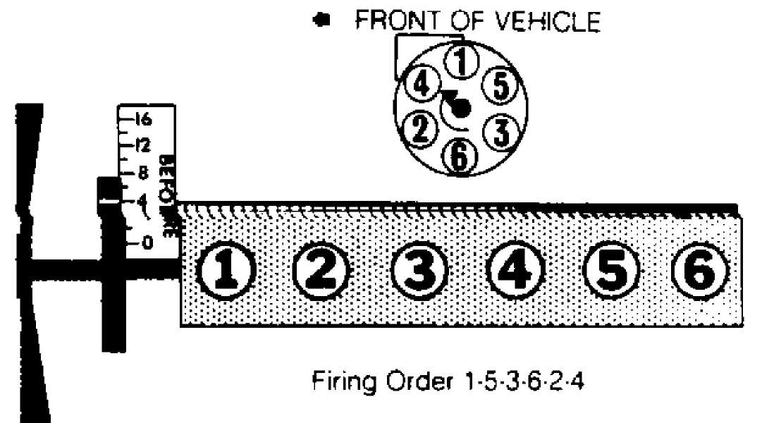
Fig. 1: 4.0L 6-Cylinder Firing Order
IGNITION CONTROL MODULE (ICM)
The ignition control module is mounted to the ignition coil. See Fig. 2. Based on control system inputs, the ECU triggers the ignition coil via the ignition control module. The ECU is able to advance or retard ignition timing by controlling the ignition coil through the ignition control module.
The ICM consists of a solid state ignition circuit, an integrated ignition circuit and an integrated ignition coil that can be removed and serviced separately if necessary.
The ECU provides an input signal to the ICM. The ICM has only two outputs:
Tach signal to the tachometer and diagnostic connector
High voltage from the coil to the distributor cap


 IGNITION
CONTROL MODULE/ IGNITION COtL ASSEMBLY
IGNITION
CONTROL MODULE/ IGNITION COtL ASSEMBLY
Fig. 2: View of Ignition Control Module/Ignition Coil Assembly
IGNITION CONTROL MODULE (ICM) ELECTRICAL FEED CONNECTIONS
Electrical feed to the ICM is through terminal "A" of Connector No. 1 on the module. See Fig. 3.
NOTE: Electrical supply only occurs with the ignition switch in the START and RUN position.
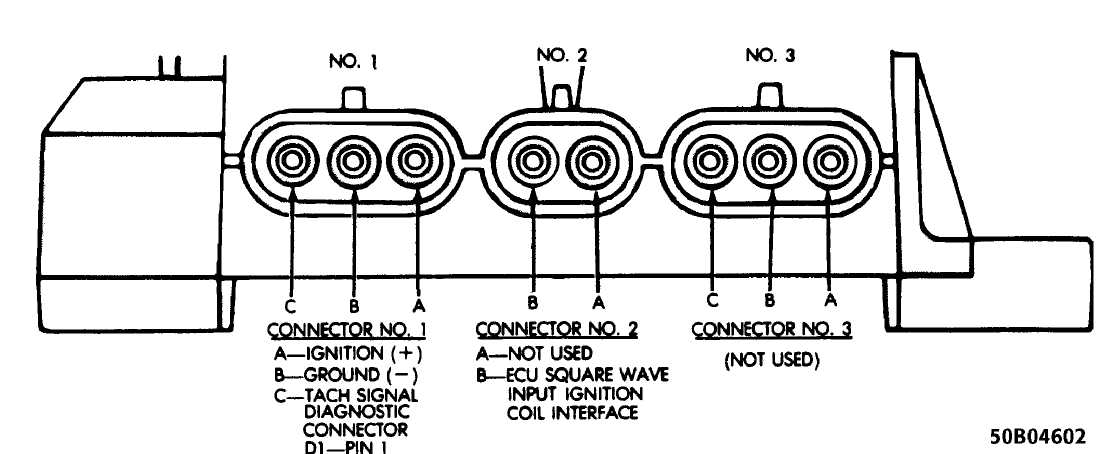
Fig. 3: Ignition Control Module Connector Identification Courtesy of Chrysler Motors.
Terminal "B" of Connector No. 1 is grounded at the engine oil dipstick bracket along with the ECU ground wire and Oxygen (O2) sensor ground.
The tachometer output signal wire of the ICM is connected to Pin No. 1 of the "D1" Diagnostic connector. The wire is routed to the diagnostic connector through a short section of the ECU harness, the engine, and the instrument panel harness. This type of routing eliminates any potential electrical interference from occurring in the various ECU circuitry.
Ignition firing signals from ECU terminal "27" are
transmitted through terminal "B" of Connector No. 2 on the ICM. the ignition signal from the ECU is received by the ICM in the form of a 5 volt square wave. As the leading edge of the wave contacts the ignition circuitry in the ICM, the ICM charges the coil primary windings.
When coil saturation occurs, the module circuitry opens the primary windings to collapse the magnetic field in the windings. This induces the coil secondary windings which is then transmitted to the spark plug via the coil wire, distributor cap, and rotor.
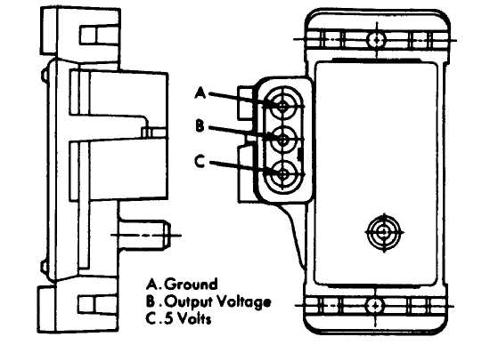
MANIFOLD ABSOLUTE PRESSURE (MAP) SENSOR
The MAP sensor reacts to absolute pressure in the intake manifold and provides an input signal to the ECU. As the engine load changes, manifold pressure varies, which causes the MAP sensor resistance to change, resulting in a different input voltage to the ECU. The input voltage level supplies the ECU with information relating to ambient barometric pressure during engine start-up or regarding engine load while the engine is running. The ECU calculates this information and adjusts the air-fuel mixture accordingly.
The MAP sensor is mounted under the hood on the firewall and is connected to the throttle body with a vacuum hose. See Fig. 4.

Fig. 4: View of Manifold Absolute Pressure (MAP) Sensor Courtesy of Chrysler Motors.
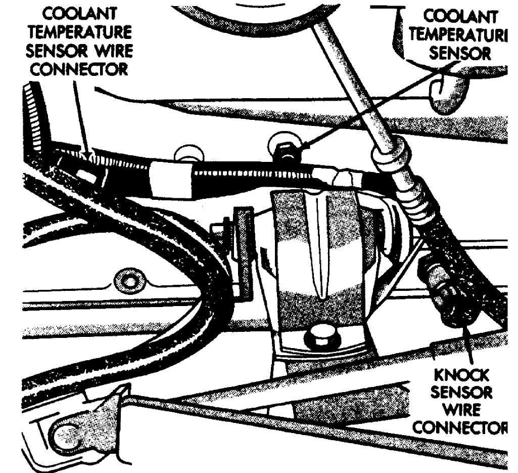
COOLANT TEMPERATURE SENSOR (CTS)
The coolant temperature sensor is installed in the engine water jacket on the left side of the engine. See Fig. 5. It provides an input voltage to the ECU. As coolant temperatures vary, the Coolant Temperature Sensor resistance changes, resulting in a different input voltage to the ECU. The ECU calculates this information and adjusts the following:
Adjust fuel injector pulse width. Colder coolant
temperatures will result in longer injector pulse width
and richer air-fuel mixtures.
Compensate for fuel condensation in the intake manifold.
Control engine warm-up idle speed.
Increase ignition advance when the coolant is cold.
Energize the EGR valve solenoid, thus preventing the flow
of vacuum to the EGR valve.
COOLANT
TEMPERATURE
SENSOR
Fig. 5: Location of Coolant Temperature Sensor (CTS) Courtesy of Chrysler Motors.
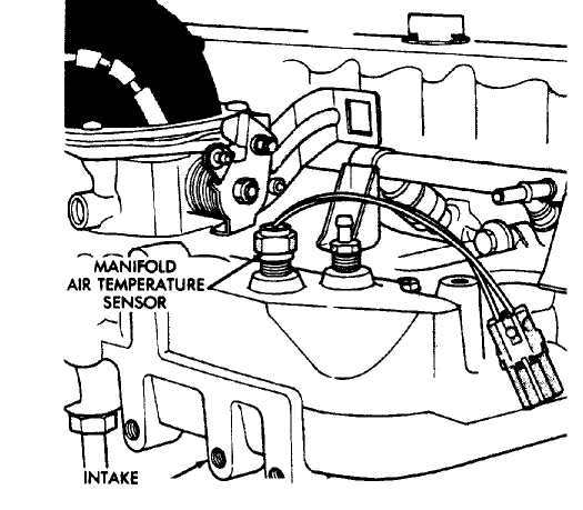
MANIFOLD AIR TEMPERATURE (MAT) SENSOR
The Manifold Air Temperature (MAT) sensor is installed in the intake manifold with the sensor element extending into the air-fuel
stream See Fig. 6. The MAT sensor provides an input voltage to the ECU. As the temperature of the air-fuel stream in the manifold varies, resistance changes, resulting in a different input voltage to the ECU.
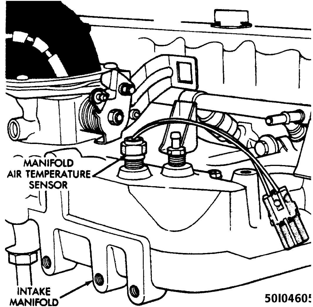 Fig.
6: Location of Manifold Air Temperature
Courtesy of Chrysler Motors.
Fig.
6: Location of Manifold Air Temperature
Courtesy of Chrysler Motors.
(MAT) Sensor
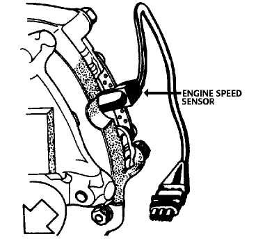
ENGINE SPEED SENSOR (CRANKSHAFT POSITION SENSOR - CPS)
The engine speed sensor is attached to the flywheel cover housing and provides an input signal to the ECU relating to crankshaft speed, angle, and position. See Fig. 7. The ECU converts crankshaft speed input into engine RPM and converts crankshaft angle to piston
position. The engine speed sensor senses TDC, BDC, and engine speed by detecting the flywheel teeth as they pass by the sensor during engine operation. The engine speed sensor is non-adjustable.
The flywheel has three trigger notches, 120 apart. See Fig. 7. There are 20 small teeth between each trigger notch. Each large trigger notch is located 12 small teeth before each Top Dead Center (TDC) position of the corresponding pistons.

Fig. 7: Location of Engine Speed Sensor Courtesy of Chrysler Motors.
When a small tooth and notch pass the magnet core in the sensor, the concentration, followed by the collapse of the magnetic
flux induces a small voltage spike to the sensor pickup coil winding. These small voltage spikes enable the ECU to count the teeth as they pass the sensor. When a large trigger tooth and notch pass the magnetic core in the sensor, the increased concentration, and then collapse of the magnetic flux induces a higher voltage spike into the sensor pickup coil winding. See Fig. 8.
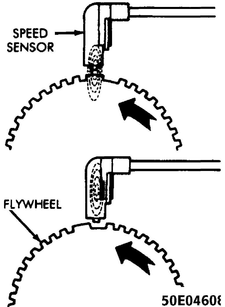
Fig. 8: Engine Speed Sensor Operation Courtesy of Chrysler Motors.
The higher voltage spike is an indication to the ECU that a piston will reach its TDC position, 12 teeth later. See Fig. 9. The
ignition timing for the particular cylinder is either advanced or retarded as necessary by the ECU according to sensor inputs.
|
|
Fig. 9: View of Engine Speed Sensor, Showing Trigger Notches & TDC
Position
Courtesy of Chrysler Motors.
SYNC PULSE SIGNAL GENERATOR (STATOR)
The sync pulse signal generator is located in the distributor and works in conjunction with the engine speed sensor to provide the ECU with input to establish and maintain correct injector firing order. See Fig. 10. A pulse ring mounted to the distributor shaft references the position of pistons one and six as it rotates through the sync pulse signal generator’s magnetic field.
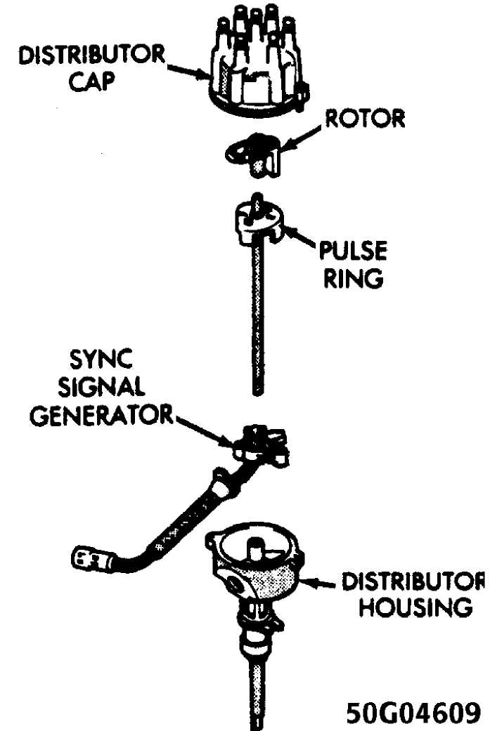
Fig. 10: Location of Sync Pulse Signal Generator & Pulse Ring Courtesy of Chrysler Motors.
The pulse ring rotates through the sync pulse signal generator for l80. When the leading edge of the pulse enters the sync
pulse signal generator, the magnetic field becomes weaker. This indicates the position of piston number one to the ECU. When the trailing edge of the pulse ring leaves the sync pulse signal generator, the magnetic field becomes stronger. This indicates the position of piston number six.
The sync pulse signal input and engine speed sensor input allow the ECU to establish the necessary reference point to synchronize the fuel injection.

Fig. 11: Sync Pulse Signal Generator Operation Courtesy of Chrysler Motors.
KNOCK SENSOR
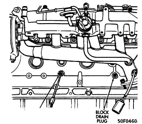
The knock sensor is located on the lower left side of the engine block just above the oil pan. See Fig. 12. The knock sensor provides an input to the ECU, indicating detonation (knock) during engine operation. When knock occurs, the ECU retards the ignition advance to eliminate the knock at the appropriate cylinder(s).

Fig. 12: Location of Knock Sensor Courtesy of Chrysler Motors.
IGNITION SYSTEM PRECAUTIONS
When disconnecting wire from spark plug or distributor cap, twist rubber boot slightly to loosen. Grasp boot (not wire) and pull with steady, even force.
When separating control unit connectors, pull with firm, straight force. Do not pry apart with screwdriver. When connecting, press together firmly to overcome hydraulic pressure of silicone grease.
If connector locking tabs weaken or break, press together firmly and bind with electrical tape or a harness tie strap to assure good connection.
COMPONENT LOCATIONS
COMPONENT LOCATIONS
 Component
Location
Coolant Temperature
Sensor (CTS) On left side of engine
Engine Speed Sensor .... Attached to flywheel cover housing
Ignition Control Module Mounted to ignition coil
Knock Sensor On lower left side of engine
Manifold Absolute Pressure
(MAP) Sensor Under the hood, on firewall
Manifold Air Temperature
(MAT) sensor On intake manifold
Sync Pulse Signal Generator Inside distributor
TESTING
BASIC DIAGNOSTIC PROCEDURES
This section contains information for determining individual system component performance. Diagnosis of ECU/Engine Control System is performed using the DRB-II Diagnostic Tester. See the appropriate Computerized Engine Control System article in this section.
COOLANT TEMPERATURE SENSOR (CTS) TEST
1) Disconnect the CTS wire harness connector from the CTS. See Fig. 13.
 COOIANT
TEMPERATURE
SENSOR
Fig. 13: Location of Coolant Courtesy of Chrysler Motors.
Temperature Sensor (CTS)
2) Using a high input impedance (digital) volt-ohmmeter, test the resistance of the sensor. Resistance should be less than l000 ohms
with a warm engine. See the COOLANT TEMPERATURE SENSOR (CTS) RESISTANCE VALUES table below.
COOLANT TEMPERATURE SENSOR (CTS) RESISTANCE VALUES
|
Degrees F |
Degrees C |
Resistance (Ohms) |
|
-40 |
-40 |
100,700 |
|
0 |
-18 |
25,000 |
|
20 |
-7 |
13,500 |
|
40 |
4 |
7,500 |
|
70 |
20 |
3,400 |
|
100 |
38 |
1,600 |
|
160 |
70 |
450 |
|
212 |
100 |
185 |
If any
resistance is not within the range as specified in
the table,
replace the coolant temperature sensor.
Test the
resistance of the wire harness between the ECU
wire harness
connector terminal "D-3" and the sensor connector
terminal
"C-10".
Repair any open circuits.
MANIFOLD AIR TEMPERATURE (MAT) SENSOR TEST
1) Disconnect the MAT wire harness connector from the MAT sensor. See Fig. 14*.
MANIFOLD*^ VZi"^ 5010460!
Fig. 14: Location of Manifold Air Temperature (MAT) Sensor Courtesy of Chrysler Motors.
2) Using a high input impedance (digital) volt-ohmmeter, test the resistance of the sensor. Resistance should be less than l000 ohms
with a warm engine. See the MANIFOLD AIR/FUEL TEMPERATURE (MAT) SENSOR RESISTANCE VALUES table below.
MANIFOLD AIR/FUEL TEMPERATURE (MAT) SENSOR RESISTANCE VALUES
|
Degrees F |
Degrees C |
Resistance (Ohms) |
|
-40 |
-40 |
100,700 |
|
0 |
-18 |
25,000 |
|
20 |
-7 |
13,500 |
|
40 |
4 |
7,500 |
|
70 |
20 |
3,400 |
|
100 |
38 |
1,600 |
|
160 |
70 |
450 |
|
212 |
100 |
185 |
If
any resistance is not within the range as specified in
the table,
replace the MAT sensor.
Test
the resistance of the wire harness between the ECU
wire harness
connector terminal "D-3" and the sensor connector
terminal
"C-8".
Repair
as necessary any circuits displaying a value
greater than one
ohm.
MANIFOLD ABSOLUTE PRESSURE (MAP) SENSOR TEST
1) Inspect the MAP sensor vacuum hose connections at the throttle body and the MAP sensor. See Fig. 15. Repair vacuum hose or connections as necessary.
50Ń04612
Fig. 15: Manifold Absolute Pressure (MAP) Sensor Connectors Courtesy of Chrysler Motors.
2) With the ignition switch ON and engine OFF, test the MAP sensor output voltage at the MAP sensor connector terminal "B". See
Fig. 15. With a hot idle condition, the voltage reading should drop to between 0.5-1.5 volts.
Test
ECU terminal "C-6" for the same voltage as described
in
step 2) to verify the wiring harness.
Repair as necessary.
Test
the MAP sensor supply voltage at the sensor connector
terminal
"C" with the ignition ON. Voltage reading should be
between
4.5-5.5 volts. Check that the
voltage reading at terminal "C-14" is
also
4.5-5.5 volts.
Repair or replace the wire harness as necessary.
Test
the MAP sensor ground circuit at the sensor connector
terminal
"A" and ECU connector terminal "D-3". Repair the
wire harness
as necessary.
Using
an ohmmeter, test the MAP sensor ground circuit at
the ECU
connector between terminal "D-3" and terminal "B-ll".
If an
open circuit is indicated, check for a defective sensor
ground
connection. The MAP sensor ground is located on the right
side of the
engine block.
If,
after performing step 7), the ground
connection is
verified to be good,
check for a short to 12 volts at terminal
"D-3".
If a short is found,
repair the short and then replace the ECU.
KNOCK SENSOR TEST
Connect Diagnostic Tester M.S. 1700 to the vehicle.
Go to "State Display" mode.
Start the engine and let idle.
Observe knock sensor value.
Using
the tip of a screwdriver, lightly tap the cylinder
block near the
sensor while observing the knock sensor value.
The
knock sensor value should increase when the cylinder
block is
tapped.
If
the knock sensor value does not increase while tapping
on
the cylinder block near the knock sensor, check for
proper
connections to the knock sensor. If connections are good,
replace
the knock sensor. Refer to
REMOVAL & INSTALLATION in this
article.
ENGINE SPEED SENSOR TEST
Disconnect
the engine speed sensor connector from the
ignition control
module.
place
an ohmmeter between terminals "A" and "B"
(marked on
the connector). On
a hot engine, the resistance reading should be
between
125-275 ohms.
Replace sensor if readings are not within specification.
50E04613
Fig. 16: View of Engine Speed Sensor Connectors (At Sensor) Courtesy of Chrysler Motors.
SPARK PLUG CHECK
Faulty or fouled plugs may perform well at idle speed, but at higher engine speeds, they frequently fail. Faulty plug can exhibit the following symptoms:
Poor fuel economy.
Power loss.
Decreased engine speed.
Hard starting.
Generally poor performance.
Spark plugs also malfunction due to carbon fouling, excessive electrode air gap, or broken insulators.
SYNC PULSE SIGNAL GENERATOR (STATOR) TEST
NOTE: For this test, an analog voltmeter MUST be used.
Insert
the positive (+) lead of the voltmeter
into the
Blue wire at the distributor connector.
Insert
the negative (-) voltmeter lead into the
Gray/White
wire at the distributor connector.
CAUTION: DO NOT remove the distributor connector from distributor. Insert the voltmeter leads into the backside of the distributor connector to make contact with the terminals.
Set
the voltmeter to the 15-Volt D/C scale. Turn ignition
key
to "ON".
The voltmeter should display approximately 5.0 volts.
If no
voltage displays, check that the voltmeter leads are
making good
contact. If there is still no voltage, go to next step.
Remove the
ECU and check for voltage at pin "C-16" and
ground with
harness connected. If there in still no voltage, proceed
to the
next step.
Connect
Diagnostic Tester M.S. 1700 to the
vehicle. Using
the diagnostic tester,
perform vehicle test. If voltage is present, go
to
the next step.
Check for
continuity between the Blue wire at the
distributor connector and
pin C-16 at the ECU.
If there in no continuity, repair harness as necessary.
Check for
continuity between the Gray/White wire at the
distributor
connector and pin C-5 at the ECU.
If there is no continuity, repair harness as necessary.
Check for
continuity between the Black wire at the
distributor connector
and ground.
If there is no continuity, repair harness as necessary.
While
observing the voltmeter, crank the engine; the
voltmeter needle
should fluctuate back and forth while the engine in
cranking. A
fluctuation verifies that the stator in the distributor is
operating
properly.
If
there is no pulse sync, replace the stator. Refer to
REMOVAL
& INSTALLATION below in this article.
REMOVAL & INSTALLATION
COOLANT TEMPERATURE SENSOR (CTS)
Removal
1) Drain the cooling system.
Remove air cleaner assembly.
Disconnect the CTS wire connector. See Fig. 17.
Remove the CTS from the left side of the engine block.

50G04614
Fig. 17: Coolant Temperature Sensor (CTS) Connector Courtesy of Chrysler Motors.
Installation
Install
the CTS to the cylinder block. Tighten the CTS
to 21 Ft.
Lbs. (28 Nm).
Connect the CTS wire connector.
Install air cleaner assembly.
Fill the cooling system.
MANIFOLD AIR TEMPERATURE (MAT) SENSOR
Removal
Disconnect the MAT sensor wire connector. See Fig. 18.
Remove the MAT from the intake manifold.
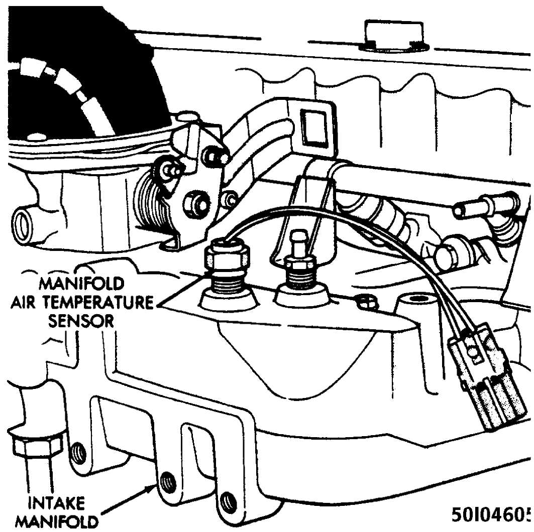
Fig. 18: Manifold Air Temperature (MAT) Sensor Connectors Courtesy of Chrysler Motors.
Installation
Install
the MAT sensor to the cylinder block. Tighten the
MAT sensor to
21 Ft. Lbs. (28 Nm).
Connect the MAT sensor wire connector.
MANIFOLD ABSOLUTE PRESSURE (MAP) SENSOR
Removal
Disconnect the MAP sensor wire connector. See Fig. 19.
Disconnect MAP sensor vacuum supply hose from MAP sensor.
Remove the
MAP sensor attaching nuts. Remove MAP sensor
from the firewall.
 Fig.
19: View of Manifold Absolute Pressure
Mounting Nuts & Vacuum
Supply Hose Courtesy of Chrysler Motors.
Fig.
19: View of Manifold Absolute Pressure
Mounting Nuts & Vacuum
Supply Hose Courtesy of Chrysler Motors.
(MAP) Sensor
Installation
Install
the MAP sensor to the firewall. Tighten the MAP
sensor attaching
nuts.
Connect the MAP sensor vacuum supply hose.
Connect the MAP sensor wire connector.
KNOCK SENSOR
Removal
Raise and support the vehicle.
Disconnect
the knock sensor wire connector located below
and
to the rear of the Coolant Temperature Sensor. See Fig. 20.
Remove knock sensor from left side of the engine block.


 50G04614
Fig. 20: Knock Sensor Connector Courtesy of Chrysler Motors.
Installation
WARNING: The knock sensor MUST be tightened to the EXACT torque specified in order to ensure proper operation.
Install
the knock sensor to the cylinder block. Tighten
the knock sensor
to 89 INCH Lbs. (10 Nm).
Connect the knock sensor wire connector.
Lower vehicle.
ENGINE SPEED SENSOR
Removal
Remove engine speed sensor wire connector. See Fig. 21.
Remove the
engine speed sensor-to-transmission housing
attaching bolts.
Remove engine speed sensor from transmission housing.
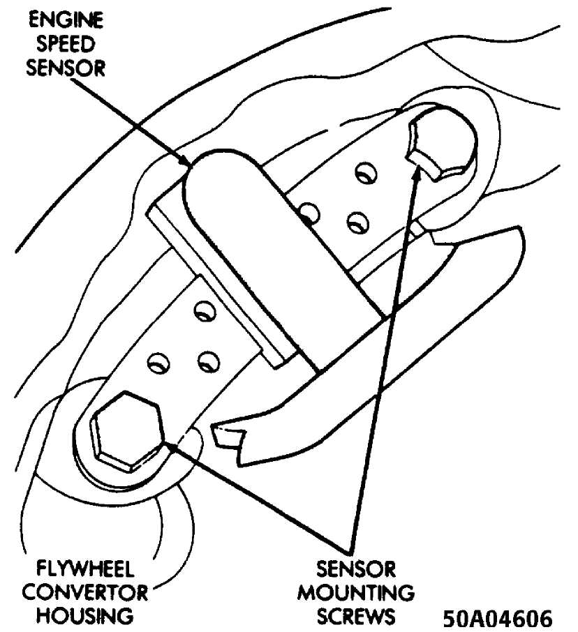
Fig. 21: Engine Speed Sensor Mounting Bolts Courtesy of Chrysler Motors.
Installation
1) Install the engine speed sensor to the transmission
housing with 2 shoulder bolts. Tighten the engine speed sensor shoulder bolts.
2) Connect the engine speed sensor wire connector.
ELECTRONIC CONTROL UNIT (ECU)
Removal
NOTE:
The ECU is located below the instrument panel, between the steering column and the A/C-Heater housing. See Fig. 22. Three screws mount the ECU to a bracket.
Disconnect the negative battery cable.
Remove the 3 ECU attaching screws. See Fig. 23.
Disconnect the ECU wiring harness connector.
Remove the ECU.
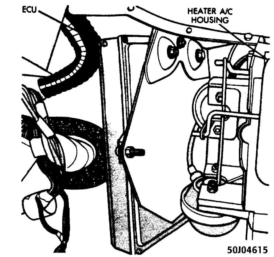
Fig. 22: Location of ECU Courtesy of Chrysler Motors.
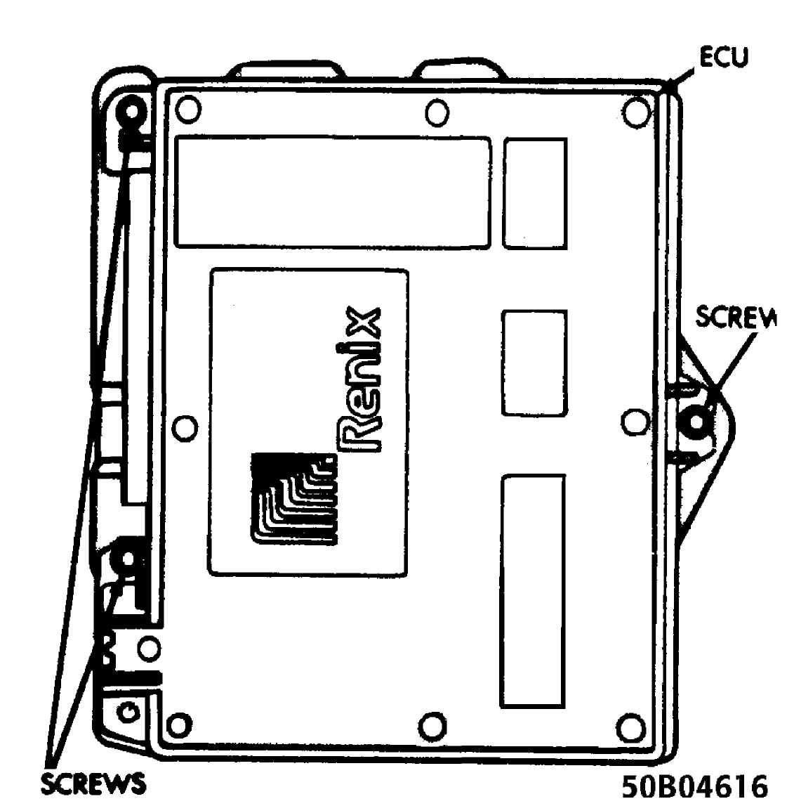
Fig. 23: Location of ECU Mounting Screws Courtesy of Chrysler Motors.
Installation
Connect the ECU wiring harness connector.
While
holding the ECU in position, attach the 3 ECU
attaching
screws. See Fig. 23.
3 Connect the negative battery cable.
DISTRIBUTOR
Removal
Disconnect the battery negative cable.
On
vehicles equipped with A/C, remove the electrical
cooling fan and
shroud assembly from the radiator to allow room to
rotate the
engine with a socket and ratchet using the vibration damper
bolt.
Scribe
a mark on the distributor housing below the left
side
(past) the number one spark plug wire post of the distributor
cap
for reassembly reference for No 1
cylinder firing position.
Remove the distributor cap.
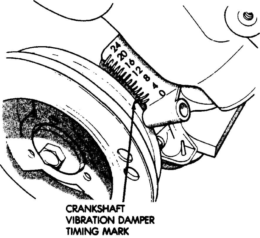
Turn
the engine in a clockwise direction until the rotor
is
approaching the scribed mark on the distributor housing. Then
slowly
turn the engine until the timing mark on the crankshaft
vibration
damper lines up with zero on the front cover timing scale.
See
Fig. 24.
NOTE:
The timing mark is located on the edge of the vibration damper closest to the front cover.
50D04617
6) Align the trailing edge of the rotor blade with the mark previously scribed on the distributor housing. See Fig. 25.
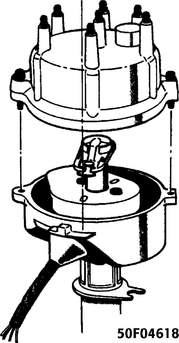
Fig. 25: Aligning Rotor & Distributor Cap for Removal Courtesy of Chrysler Motors.
Remove the distributor hold-down bolt and clamp.
Remove the distributor from the engine.
Installation
1) If needed, use a flat blade screwdriver to turn the oil pump gear shaft until the slot is slightly past the 11 o’clock position. See Fig. 26. The oil pump shaft is located down in the distributor hole.
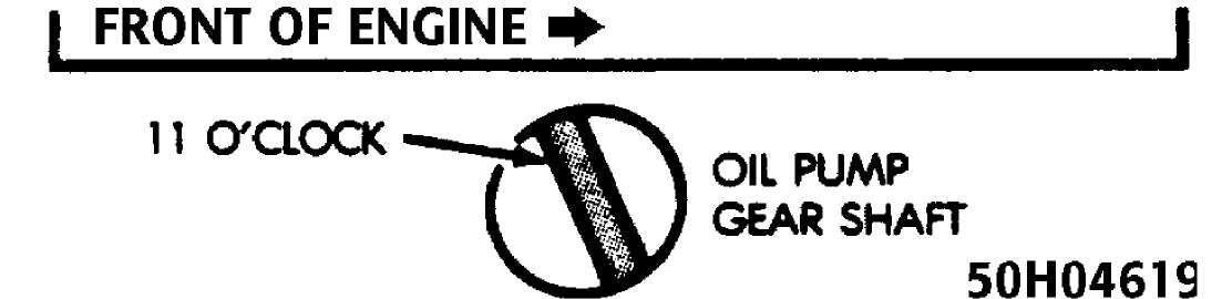
Fig. 26: Aligning Oil Pump Gear Shaft Courtesy of Chrysler Motors.
Install the rotor.
Without
engaging the distributor gear into the cam gear
and ensuring the
distributor gasket is installed, position the
distributor into
the hole in the engine block.
Visually
line up the hold down ear of the distributor
housing
with the hold down clamp hole. See Fig. 27.
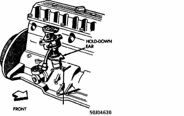 HOLD-OOWN
CLAMP BOLT HOLE
HOLD-OOWN
CLAMP BOLT HOLE
Fig. 27: Installing Distributor Courtesy of Chrysler Motors.
5) Turn the rotor to the 4 o’clock position. See Fig. 28.
12 O’CLOCK
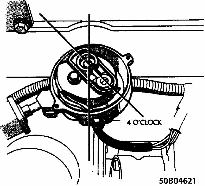 Fig.
28: Installing &
Aligning Rotor Courtesy of Chrysler Motors.
Fig.
28: Installing &
Aligning Rotor Courtesy of Chrysler Motors.
Carefully
slide the distributor into the block until it
seats, keeping the
hold down ear aligned to the hole in the block.
The
rotor should be in the 5 o’clock position
with the
trailing edge of the rotor blade lined up with the mark
previously
scribed on the distributor
housing (number one spark plug wire post
location).
install
the distributor hold-down clamp bolt and tighten
to
9.5-14 Ft. Lbs. (13-19 N.m).
Install
the distributor cap. Connect the distributor
electrical
connector.
Install
the electric cooling fan and shroud if
applicable.
Connect the negative battery cable.
IGNITION/COIL WIRE REPLACEMENT PRECAUTIONS
Removal & Installation
Using care, disconnect the spark plug and coil wire boots and wires. Twist the boot one half turn and pull on the boot to disconnect the wire.
When replacing the spark plug and coil wires, carefully route the wires correctly and secure them in their proper channels retainers.
Failure to route the wires properly can cause the radio to reproduce ignition noise, cross ignition of the plugs, or can short circuit the wires to ground.
OVERHAUL
STATOR REPLACEMENT
Disassembly
Remove
the distributor as specified in DISTRIBUTOR under
REMOVAL &
INSTALLATION above in this article.
Remove the distributor rotor.
Position the distributor in a vise.
Remove
the distributor gear from the shaft using a small
punch and a
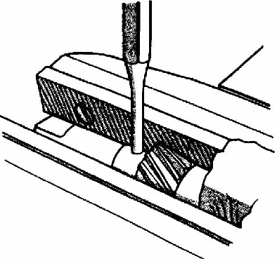
hammer to drive out the retaining roll pin. See Fig. 29.
Remove the distributor shaft from the distributor housing.
Remove the stator retaining screw.
NOTE:
Mark the location of the stator position for reassembly reference.
 50D04622
Fig. 29: Removing Distributor Gear Retaining Roll Pin Courtesy of Chrysler Motors.
7) Remove stator harness by pushing the grommet through the distributor housing. Remove stator assembly. See Fig. 30.
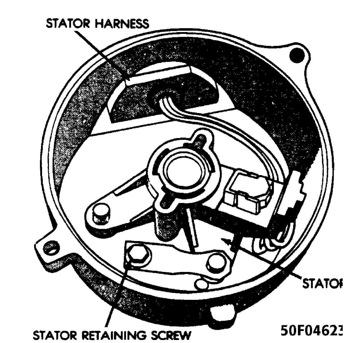
Fig. 30: Location of Stator Retaining Screw Courtesy of Chrysler Motors.
Reassembly
Install stator assembly and the stator retaining screw.
Position
the stator assembly harness through the
distributor housing and
push the grommet into position.
Install
distributor shaft into the distributor housing. If
the shaft is
equipped with seals, ensure that they are in place and
not
damaged.
Install
the distributor gear washer and distributor gear
onto the shaft.
Install the distributor gear retaining pin.
Install the distributor rotor.
Install
the distributor as specified in DISTRIBUTOR under
REMOVAL &
INSTALLATION above in this article.
TORQUE SPECIFICATIONS
TORQUE SPECIFICATIONS
Application Ft.
Lbs. (N.m)
Coolant Temperature Sensor 21 (28)
Distributor Hold-Down Clamp Bolt 9.5-14 (13-19)
Manifold Air Temperature Sensor 21 (28)
INCH Lbs. (N.m)
Knock
Sensor 89 (10)