STEERING GEAR - MANUAL
1988 Jeep Cherokee
1988 STEERING
Jeep Manual Steering Gears
Koyo & Saginaw Recirculating Ball
Cherokee, Comanche, Wrangler
DESCRIPTION
Jeep uses the Saginaw steering gear unit. Different models are used. The Model 525 uses 3 bolts in the side cover while the Model 535 uses 4 bolts.
Steering gears are a recirculating ball-type. Proper
engagement between sector and ball nut is obtained by adjusting screw. Worm bearing adjuster can be turned to provide proper preloading of upper and lower bearings.
TROUBLE SHOOTING
Refer to TROUBLE SHOOTING - BASIC PROCEDURES article in the GENERAL TROUBLE SHOOTING section.
ADJUSTMENTS
NOTE: Adjust worm bearing preload prior to performing meshload adjustment. If steering gear is removed, install INCH lb. torque wrench on worm shaft to check preload adjustments.
WORM BEARING PRELOAD
1) Place reference mark on pitman arm and sector shaft.
Remove pitman arm retaining nut. Using puller, remove pitman arm from sector shaft.
Disconnect pitman arm from ball stud or sector shaft.
Remove
horn pad. Turn steering wheel slowly against one
stop
then back 1/2 turn. Place an INCH-lb.
torque wrench with a
maximum reading of
50 INCH lbs. (6 N.m)
on steering wheel nut.
Measure
amount of torque (preload) required to rotate
steering
wheel at a constant speed for approximately 1 1/2 turns
on
Ford Motor Co. models or 90 degree
arc on all others.
Note
preload. Adjust preload if not within specification.
See WORM
BEARING PRELOAD table. Adjust preload by loosening lock nut
(if
not previously loosened) and rotating worm bearing adjuster
to
obtain correct preload.
Once
correct preload is obtained, tighten lock nut to
specification.
Perform meshload adjustment once correct preload is
obtained.
WORM BEARING PRELOAD TABLE
 Application INCH
Lbs. (N.m)
Application INCH
Lbs. (N.m)
Cherokee, Comanche & Wrangler 5-8 (.6-.9)
MESHLOAD ADJUSTMENT
1) Rotate steering wheel from stop-to-stop, noting the number of revolutions. Rotate steering wheel back to the center position.
2) Ensure sector shaft cover bolts are tightened to
specification. Using an INCH lb. torque wrench, measure highest torque required to rotate steering wheel back and forth through the center position. Meshload must be adjusted if not within specification. See the MESHLOAD SPECIFICATIONS table.
MESHLOAD SPECIFICATIONS TABLE
 Application INCH
Lbs. (N.m)
Application INCH
Lbs. (N.m)
Cherokee, Comanche & Wrangler (1) 4-10 (.5-1.1)
(1) - In excess of worm bearing preload. Maximum preload is 18 INCH lbs. (2.0 N.m) on Jeep models or 16 INCH lbs. (1.8 N.m) on all others.
Loosen
sector shaft adjuster screw lock nut. Adjust sector
shaft
adjuster screw to obtain correct reading. Tighten lock nut
to
specification while holding adjusting screw.
Reverse
removal procedures for components removed. Ensure
reference
mark is aligned on pitman arm and sector shaft. Tighten
pitman
arm retaining nut to specification. On Jeep models, stake
pitman
arm retaining nut in 2 places.
REMOVAL & INSTALLATION
STEERING GEAR
CAUTION: All steering component fasteners are made of special quality materials. Replacement fasteners must be of same part number or equivalent. Tighten all fasteners to proper torque. Install new cotter pin where used.
Removal
Disconnect
negative battery cable. Set front wheels in
straight-ahead
position. Note position of steering wheel. Remove
flexible
coupling shield retaining screw (if equipped).
Remove
flexible coupling-to-steering worm shaft flange
bolts or lower
universal joint pinch bolt. Remove sector shaft nut and
washer.
Place reference mark in relation of pitman arm-to-sector
shaft.
Using Puller (J-6632-01), remove pitman arm. Remove
steering
gear-to-frame bolts. Remove steering gear.
Installation
Install
flexible coupling on worm shaft. Align flat on
coupling
with flat on worm shaft. Push coupling on shaft until shaft
touches
shoulder. Install pinch bolt. Pinch bolt must pass through
shaft
undercut.
To install remaining components, reverse removal
procedure. Align reference mark on pitman arm and sector shaft. Ensure splines are properly aligned. Tighten bolts to specification. On Jeep models, stake sector shaft nut in 2 areas.
SECTOR SHAFT SEAL
NOTE: On some models, sector shaft seal may be replaced without removing steering box. It may be necessary to remove steering gear to gain access to remove sector shaft seal.
Removal & Installation
1) Place steering gear at center of travel. Remove sector
shaft nut. Place reference mark in relation of pitman arm-to-sector shaft. Using puller, remove pitman arm.
Remove
sector shaft cover retaining bolts. Lift sector
shaft and cover
from housing. Using a screwdriver, pry sector shaft
seal from
housing. Use care not to damage housing area. Note direction
of
seal installation.
Loosen
sector shaft adjusting screw lock nut. Rotate
adjusting screw
clockwise and remove cover from sector shaft. Inspect
gear
lubricant for contamination. Steering gear must be overhauled
if
contamination exists.
Lubricate new sector shaft seal with steering gear
lubricant. Position seal in housing bore. Using proper sized socket, tap seal into housing until it bottoms.
Install
sector shaft so center tooth of sector shaft
enters
center tooth of ball nut. Fill housing with lubricant. Install
new
sector shaft cover gasket on gear housing (if equipped).
Apply a
thin bead of sealant to sector shaft
cover on models which do not use
a
gasket.
Using
a screwdriver through the center hole, align
adjusting screw and
install cover on sector shaft. See Fig. 1. Turn
adjusting
screw counterclockwise until screw bottoms, then back off
1/4
turn.
Coat cover
bolts with non-hardening sealant. On all
models, install cover
retaining bolts. Tighten to specification.
Install sector shaft
lock nut. Perform adjustments on steering box.
See ADJUSTMENTS in
this article.


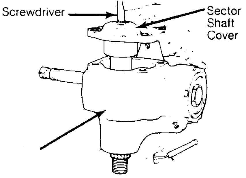
Housing
Fig. 1: Installing Sector Shaft Cover
OVERHAUL
STEERING GEAR
Disassembly
Place
steering gear in a holding fixture. Worm shaft
should be centered
in steering gear. Remove sector shaft cover bolts.
Remove sector
shaft and cover from housing.
Remove sector shaft adjusting screw lock nut. Rotate
adjusting screw clockwise to remove cover from shaft. DO NOT lose shim located on adjusting screw.
3) Loosen
worm bearing adjuster lock nut. Remove worm bearing
adjuster
and worm shaft lower bearing. Remove worm shaft and ball nut
assembly
from housing. Remove upper bearing.
CAUTION: DO NOT allow ball nut to rotate down worm shaft as ball guides may be damaged.
If ball
nut fails to rotate smoothly on worm shaft,
disassembly is
required. Remove ball guide clamp and guides. Rotate
worm shaft
in both directions to remove balls. Note and record number
of
balls in each circuit area of the ball nut.
Note
direction of ball nut on worm shaft prior to removal.
Remove ball
nut from worm shaft.
CAUTION: Note and record number of balls removed from each circuit of ball nut during disassembly. Determine location of ball nut on worm shaft prior to removal. Ball nut must be installed on worm shaft with shallow teeth in proper direction.
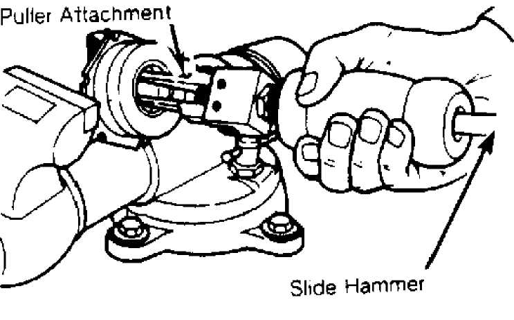
Use
slide hammer and puller attachment to remove worm
bearing
adjuster bearing cup. See Fig. 2. Using a
bearing driver or
socket, remove
bearing cup from housing.
Remove
bearings from housing. Pry out all seals from
housing. Note
direction of seals.
30301
Fig. 2: Removing Worm Adjuster Bearing Cup
Cleaning & Inspection
1) Clean components with solvent and dry with compressed air. Inspect bearings and races for signs of wear. Inspect ball nut and
worm shaft for wear or pitting.
2) Inspect
sector shaft fit at side cover bushing assembly
(if
equipped). Bushing is replaceable.
3) Inspect
housing for cracks or damage. Inspect bearings for
damage. Inspect
sector gear teeth for chipping or excessive wear.
Replace
components as necessary.
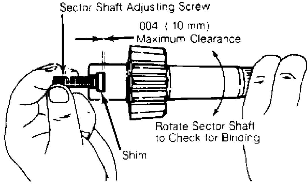
Reassembly
1) Install sector shaft adjusting screw and shim in sector shaft. Using feeler gauge, measure clearance between adjusting screw and bottom of sector shaft "T" slot. See Fig. 3.
30302
Fig. 3: Checking Sector Shaft "T" Slot Clearance
2) Different thickness shims should be used if clearance is not within specification. See ADJUSTING SCREW CLEARANCE SPECIFICATIONS table.
ADJUSTING SCREW CLEARANCE SPECIFICATIONS TABLE
Application
Cherokee, Comanche & Wrangler
In. (mm) .002 (.05)
3)
Once correct shim is determined, install
shim and adjusting screw. Hold sector adjuster screw while turning
sector shaft. If sector shaft does not
turn freely, increase clearance by
replacing shims as necessary.
Install
ball nut on worm shaft. Ensure ball nut is
installed so shallow
end of teeth are to the left as viewed from
steering wheel end of
worm shaft. Align grooves in worm and nut by
sighting through
ball guide holes.
There
are 2 types of ball guides used. One type
contains a
hole in the middle, while
the other does not. If ball guides contain
the
middle hole, install ball guides in the ball nut.
Divide
balls into 2 equal groups. Insert each
group into a
ball guide, while slowly turning worm shaft away
from the hole. Repeat
procedure for remaining circuit.
On guides
with no holes, separate guide halves and fill
each one half of
each circuit with balls. Install remaining guide
half. Hold
guides and plug ends with grease to prevent the balls from
falling
out.
Fill each
circuit of ball nut with half of remaining balls
in one circuit,
and half in other. DO NOT turn worm shaft while
installing. It
may be necessary to use small punch to aid in ball
installation.
Install ball guides. On both types, install ball guide
ńlamp.
9) To
install, reverse removal procedure. Lubricate all
seals,
bearings and sector shaft prior to installation. Coat worm
bearing
adjuster, sector shaft adjuster screw and sector shaft cover
bolts
with non-hardening sealant prior to installation.
Screw worm
bearing adjuster down until nearly all end
play has been removed.
Lubricate steering gear by rotating worm shaft
until ball nut is
at end of its travel.
Pack as much grease as possible into steering gear
housing without losing it out sector shaft opening. Rotate ball nut to other end of its travel and pack more grease into housing.

Fig. 4: Exploded View of Saginaw Model 525 Steering Gear (Typical)
TORQUE SPECIFICATIONS
Rotate
ball nut until it is in center of its travel.
Insert sector shaft
assembly, containing adjusting screw and shim into
housing.
Center tooth of sector gear must engage center rack tooth
space
in ball nut.
Pack
housing with grease. Apply a thin bead of sealant to
sector shaft
cover on models which do not use gasket. Install cover
and gasket
on housing. Engage sector adjuster screw with tapped hole
in
center of sector cover by turning screw counterclockwise.
Turn
adjusting screw until sector cover is flush with
housing.
Install sector cover bolts but do not tighten unless there is
a
lash between sector shaft and worm shaft.
Tighten
sector cover bolts to specification. Adjust
steering gear preload
and meshload. See ADJUSTMENTS in this article.
TORQUE SPECIFICATIONS TABLE
Application Ft.
Lbs. (N.m)
Adjuster Screw Lock Nut 25 (34)
Flex Coupling Pinch Bolt 45 (61)
Sector Shaft Nut 185 (252)
Sector Cover Bolt 32 (43)
Steering Gear-to-Frame Bolt 75 (102)
Worm Bearing Adjuster Lock Nut 50 (68)