STEERING COLUMN
1988 Jeep Cherokee
1988 STEERING
Jeep Steering Columns
All Models
DESCRIPTION
All models use collapsible steering columns. All columns have integral ignition switch and locking device. Optional tilt wheel is available with both A/T and M/T. Transmission shift linkage is integral on all models except those with floor shift.
TROUBLE SHOOTING
Refer to TROUBLE SHOOTING - BASIC PROCEDURES article in the GENERAL TROUBLE SHOOTING section.
REMOVAL & INSTALLATION
NOTE: Steering column removal and installation procedures refer to all manufacturers. Not all procedures, however, apply to all models.
STEERING COLUMN (COLUMN SHIFT)
Removal
Disconnect
battery negative cable. Disconnect transmission
shift cable rod
by prying rod from grommet in shift lever. Remove
cable clip.
Remove cable from lower bracket.
Disconnect,
as equipped, either the flexible coupling,
"Pot"
coupling or "U" joint from pinion shaft.
Disconnect
wiring connectors at column jacket. Remove
steering wheel and
horn pad. See STEERING WHEEL & HORN
REMOVAL
article. Remove damper assembly
(if equipped). On RWD models, remove
turn
signal lever.
On all
models, remove steering column-to-floor pan
attaching screws.
Expose steering column bracket. Remove instrument
panel steering
column cover. Lower reinforcement. Disconnect bezel.
Remove
indicator set screw and gearshift pointer from shift housing.
Remove
steering column bracket-to-instrument panel
attaching nuts. Lower
support bracket. Firmly grasp steering column
assembly and pull
rearward while disconnecting lower stub shaft from
pinion shaft
coupling.
NOTE: On vehicles equipped with cruise control and M/T, take care not to damage clutch pedal cruise control switch.
30241
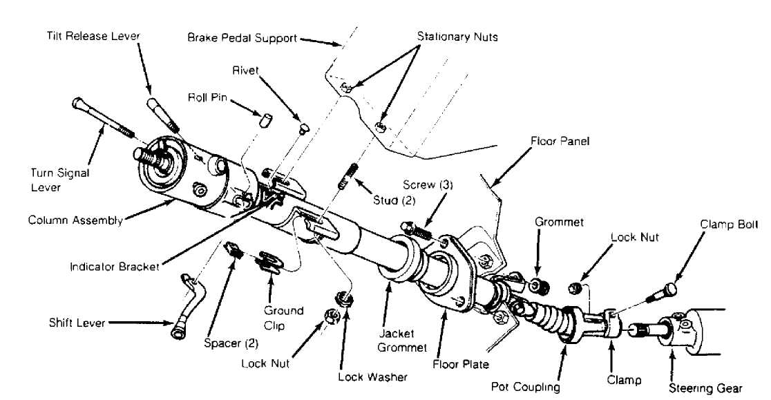
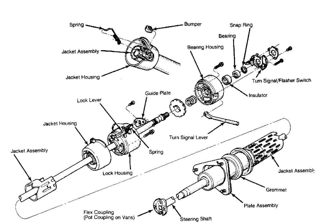
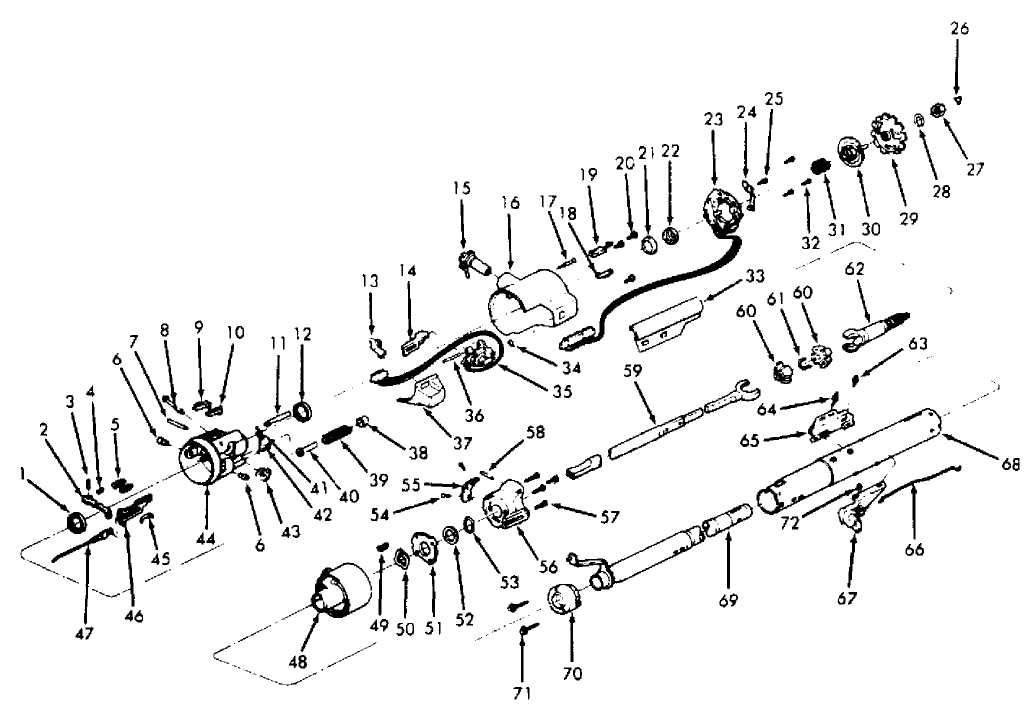
Fig. 1: Exploded View of RWD Steering Column Major Assemblies
Installation
On all
models, aligning lower shaft with lower coupling
and insert
shaft. Raise column assembly into position onto studs.
Loosely
install nuts and washers in breakaway capsules. Pull
column
rearward. Tighten nuts to specification. See TORQUE
SPECIFICATIONS.
Install a
new shift lever grommet using pliers and back-up
washer to snap
the grommet into place. Use a multipurpose grease to
aid
installation.
Connect
gearshift cable rod to shift lever by snapping rod
into
grommet with pliers. Adjust linkage. Place steering wheel on
shaft
with master splines aligned. Place damper assembly inside
steering
wheel (if equipped). Install steering
wheel retaining nut.
Tighten to 45
ft. lbs. (61 N.m).
Install
horn pad assembly. Refer to procedures in the
STEERING WHEEL &
HORN REMOVAL article. Connect wiring connectors
at
steering column jacket. Connect
battery negative cable. Test operation
of
lights and horn.
On
models with A/T, install gearshift indicator pointer.
Slowly
move gearshift lever from "LOW" position to "PARK"
position,
pausing briefly at each selector position. Loosen and
readjust to
align pointer with each position (if necessary).
Install instrument
panel
steering column cover.
STEERING COLUMN (FLOOR SHIFT)
The steering column with a floor mounted gearshift is basically the same as previously described. Standard columns and service procedures are identical except as described below.
* In place of rotating shift housing, there is a plastic shroud which is fixed to lock housing. Shroud covers jacket and lock inhibitor assembly. It is held in place by a tab that fits under side cover and one screw. Shroud can only be replaced by removing lock housing from jacket.
The
lock inhibitor assembly consists of a lever that engages
lock
levers (preventing locking of steering shaft), a
button
to operate lever and a return
spring. Assembly is attached to
lock
housing in same location as shift gate is on column
shift.
Lower steering shaft bearing is mounted in an aluminum
support.
A spring
is attached between shift housing and column jacket.
This spring
keeps housing rotated counterclockwise against
rubber bumper.
OVERHAUL
STANDARD COLUMN
NOTE: All columns are similar except for appearance of covers. Some models use ignition key light, while others do not. Disassembly and reassembly procedures cover all models. Some procedures may not apply to every steering column.
Disassembly
Pry out
wiring trough retainers. Lift off trough. New
retainers may be
required for reassembly. Use masking tape to protect
paint and a
deep socket to back-up housing. Drive retaining roll pin
out with
a punch to remove shift lever.
Remove breakaway capsules. Secure column in vise by
clamping at column bracket. DO NOT distort column. Remove turn signal lever cover-to-lock housing attaching screws. Remove cover. Remove wiper/washer switch assembly. Pull switch cover up wiper/washer lever. Remove lever sleeve-to-switch attaching screws.
Rotate
wiper/washer shaft to full clockwise position.
Remove shaft from
switch. Remove turn signal switch and upper bearing
retaining
screws. Remove retainer. Lift switch upward out of way.
Unclip
horn ground wire. Remove ignition key light retaining screw.
Lift
ignition key light out of way.
Remove
bearing housing-to-lock attaching screws. Remove
snap ring from
upper end of steering shaft. Remove bearing housing
from
shaft. Remove lock plate spring and lock
plate from shaft. Remove
shaft through
lower end of column.
Remove ignition key. Remove warning switch retaining
screw. Lift out key warning switch. Remove 2 ignition switch-to-column jacket retaining screws. See Fig. 2. Remove ignition switch by rotating switch 90 degrees on actuator rod. Remove 2 dimmer switch retaining screws. Disengage dimmer switch from rod.
30450
Fig. 2: Removing Ignition Switch
Remove
bellcrank mounting screws. Slide bellcrank up in
housing until it
can be disconnected from ignition switch rod. Using
key, place
cylinder in "LOCK" position. Remove key.
Using a
small diameter screwdriver or similar tool, push
inward to
release spring-loaded lock retainer while pulling lock
cylinder
from housing bore. Pull lock lever and spring assembly out
of
housing as an assembly.
Remove
4 lock housing-to-column jacket retaining
screws.
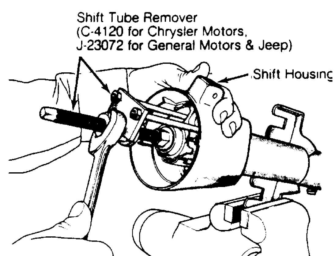
Remove housing from jacket. On A/T models, loosen shift
tube set screw
in shaft housing. On all models, using Shift Tube
Remover (J-23072 for
Jeep), remove tube through lower end of
jacket. See
Fig. 3.
9) To
disassemble flexible coupling, remove 4 bolts
and 2
cross straps. Remove flexible
coupling. "Pot" coupling is removed by
prying cover
tangs from coupling body and lifting seal and cover from
body.
Drive dowel pin down into coupling. Discard "Pot" coupling.
Pull
body off shaft and shoe assembly.
 30249
30249
Fig. 3: Removing Shift Tube

Fig. 4: Removing Lock Cylinder
Reassembly
1) Coat all friction surfaces with grease. Clamp column in vise so that both ends of column are accessible. Check column tube-to-
 mandrel
rivets for tightness.
mandrel
rivets for tightness.
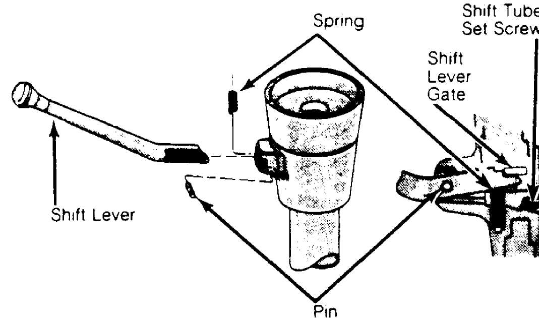
2) Use new 1/8" diameter by 1/4" long (1/8" grip) aluminum blind rivets (if necessary). DO NOT use steel rivets as rivets must shear upon impact. Position crossover load spring and shift lever in gearshift housing. Tap pivot pin into place. See Fig. 5.
30250
Fig. 5: Installing Column Shift Lever Courtesy of Chrysler Motors
Assemble
key cylinder plunger spring. Install assembly on
lock
housing. Install shift lever gate on lock housing. Place shift
lever
in mid position (if equipped). Seat lock
housing on top of
jacket by aligning
keyway in housing with slot in jacket. Install
housing-to-jacket
screws. Tighten alternately to 90 INCH
lbs. (10 N.
m) .
Install
dimmer switch rod by firmly pushing rod into
switch.
Compress switch until 2 (.093") drill
bit shanks can be
inserted into
alignment holes. Reposition upper end of push rod in
pocket
of wiper/washer switch. Remove lower column cover (if
necessary).
Remove drill bits.
Switch
should click when lever is lifted and again as
lever returns,
just before it reaches stop in down position. Grease
and
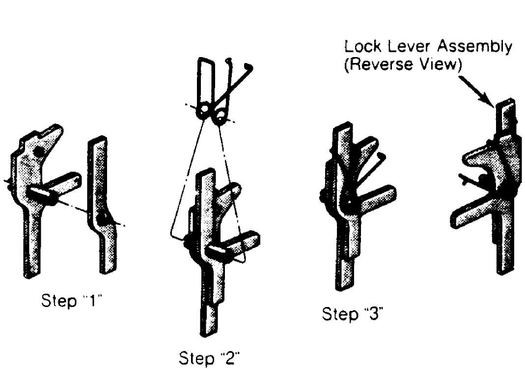
assemble 2 lock levers, lock lever spring
and pin. See Fig. 6.
Install assembly
into lock housing. Seat pin firmly in bottom of
slots.
Ensure that lock lever spring leg is firmly in place in lock
casting
notch. See Fig. 7.
30251
Fig. 6: Assembling Lock Lever & Spring Assembly
 Lock
Lever & Spring
Assembly
Lock
Lever & Spring
Assembly
30452
Fig. 7: Installing Lock Lever & Spring Assembly
6) Install ignition switch actuator rod from bottom through oblong hole in lock housing. Attach rod to bellcrank. Position bellcrank assembly into lock housing while pulling ignition switch and
rod down column. Install bellcrank onto its mounting surface. Gearshift lever should be in "PARK" position.
Place
ignition switch on actuator rod. Rotate switch 90
degrees
to lock rod into position. Install ignition lock by turning
key
to "LOCK" position. Remove key. Insert cylinder into
housing far
enough to contact switch
actuator. Insert key. Press inward. Rotate
cylinder.
When parts
align, cylinder will move inward and spring
loaded retainers will
snap into place, locking cylinder in housing.
With cylinder and
ignition switch in "LOCK" position, tighten
ignition
switch mounting screws.
Feed key
warning switch wires behind wiring post and down
through space
between housing and jacket. Remove ignition key.
Position
cylinder in housing. Tighten mounting screws. Install lower
bearing
support (floor shift), bearing and spring on steering shaft.
Install
and lubricate rubber "O" ring in
lower groove on
upper end of steering
shaft. Insert steering shaft assembly into
column
assembly. Press upper bearing into upper bearing housing.
Bearing
must be fully seated.
Push
up on steering shaft to compress bearing and spring.
Hold
shaft in this position until snap ring is installed. Install
lock
plate on steering shaft. Install
upper bearing spring. Install upper
bearing housing with bearing
previously installed. Tighten bearing
housing
retaining screws to 35 INCH lbs (4
N.m).
Install
upper bearing snap ring on steering shaft,
locking
assembly into position. Install 4 screws
attaching bearing
housing to lock
housing. Install ignition key lamp assembly in bearing
housing.
Install turn signal switch in bearing housing.
Feed turn
signal switch and ignition key lamp wires
through opening between
bearing housing and lock housing and down
along bottom of jacket.
Install bearing retainer plate. Tighten
screws. Ensure that
ground wires from turn signal switch are
positioned toward ground
clips before tightening.
Assemble
wiper switch, shaft, cover or speed control
switch, switch cover
and knob. Place wiper/washer switch assembly into
lock housing,
feeding wires through lock housing. Fasten wires to turn
signal
switch. Install dimmer switch rod and dimmer switch.
Install
turn signal lever cover. Install breakaway
capsules. Install
wiring trough in place, being careful not to pinch
wires. Install
new retainers (if necessary).
Bearing Assembly
Shoe Release Lever
Release Lever Pin
Release Lever Spring
Spring
6 Pivot Pin
Dowel Pin
Drive Shaft
9 Steering Wheel Lock Shoe
Steering Wheel Lock Shoe
Lock Bolt
Bearing Assembly
Tilt Lever Opening Shield
Dimmer Switch Rod Activator
Cylinder Lock Assembly
Lock
Housing Cover
17 Lock Retaining Screw
Buzzer Switch Retaining Clip
Buzzer
Switch Assembly
20 Screw
21. Inner Race
22 Inner Race Seal
Turn
Signal/F-lasher
Switch Assembly
Turn Signal Arm Assembly
25 Screw 26. Retainer
Jam Nut
Retaining Ring
Lock Plate
Turn Signal Cancelling Cam
Sprsng
Screw
Wiring Trough
Pin Preload Spring
Pivot & Switch Assembly
Switch
Actuator Pivot Pin
37 Column Cover End
Cap
Spring Retainer
Tilt Spring
Spring Guide
Spring
Screw
Switch Actuator Sector
Steering Column Housing
Rack
Preload Spring
46. Switch Actuator
Rack
47 Ignition Switch Acluator
49
Gearshift Lever Sowl
49 Shift
Lever Spring
Wave Washer
Jacket Mounting Ptate
Thrust Washer
Shift Tube Retaining Ring
Screw
Shift Lever Gate
Column Housing Support
Screw
Dowel Pin
Lower Steering Shaft Assembly
Centering Sphere
Joint Preload Spring
Race & Upper Shaft Assembly
Screw
Mounting Stud
Ignition
Switch Assembly
66 Dimmer Switch Rod
Dimmer Switch Assembly
Steering Column Jacket
Shift Tube Assembly
Adapter & Bearing Assembly
Screw
72,
Nut
30254
Fig. 8: Exploded View of Tilt Steering Column
TILT WHEEL COLUMN
Disassembly
Remove
lower bracket assembly-to-lower bearing support
bolts. On column
shift models, remove shift housing cover. On floor
shift models,
unsnap and remove shroud extensions. Remove wiring
protector from
column jacket.
Mount
column in vise at capsule bracket. Mount Holding
Fixture (C-4132)
onto column. Mount holding fixture and column in
vise.
Remove
tilt lever. To remove hazard warning knob, push in
knob while
unscrewing. Remove ignition key light assembly. Pull knob
off
wiper/washer switch assembly. Pull hider up switch lever. Remove
2
sleeve-to-wiper/washer switch
retaining screws. Remove sleeve.
Rotate
shaft in wiper switch fully clockwise. Remove shaft
by pulling
straight out of wiper/washer switch. Carefully remove
plastic
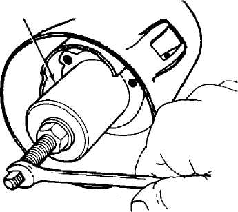
cover from lock plate. Using Lock Plate Depressor (J-23653-A
for
Jeep), depress lock plate. Pry retaining ring from groove.
Remove
lock plate, canceling cam and upper bearing plate.
Remove
switch actuator screw and arm. Remove 3 turn
signal switch
attaching screws. Place
shift bowl in "LOW" position. Wrap a piece of
tape
around wires to prevent snagging when removing switch. Remove
switch
and wiring.
Remove key
light. Place lock cylinder in "LOCK" position.
Insert a
small screwdriver into slot next to switch mounting screw
boss.
Depress spring latch at bottom of slot. Remove lock.
Using a
paper clip, remove key warning switch. Bend one
end of clip into
a hook. Insert hook into exposed loop of wedge
spring. Pull clip.
Remove spring and switch. DO NOT allow spring to
fall into
steering column.
Remove
3 housing cover screws. Remove housing
cover.
Remove wiper/washer switch. Using a punch, press out wiper
switch
pivot pin (if necessary).
Tilt lever opening shield and dimmer
switch
actuator rod may be removed from
cap (if necessary).
Place
column in fully upright position. Using a large
Phillips
screwdriver, remove tilt spring retainer. Insert screwdriver
in
opening. Push in approximately 3/16". Turn
approximately 1/8 turn
clockwise
until ears align with grooves in housing. Remove spring and
guide.
Remove
dimmer switch mounting screws. Remove dimmer
switch. Separate
dimmer switch from rod by pulling on rod. Push upper
steering
shaft in far enough to remove steering shaft inner race seat
and
inner race. With ignition switch in "ACC" position,
remove
ignition switch mounting screws and switch. Place Pivot
Pin Remover
(J-21854-01 for Jeep) over pivot pin. Thread small
portion of screw
firmly into pin.
Hold screw
from turning with one wrench while turning nut
clockwise with a
second wrench to withdraw pivot pin from support.
Remove opposite
pivot pin in same manner. Use tilt release lever to
disengage
lock shoes. Remove bearing housing assembly by pulling
upward to
extend rack fully.
Move housing assembly left to disengage rack from
actuator. Rotate housing clockwise to free dimmer switch actuator rod. Remove activator assembly. Remove coupling from lower end of steering shaft. Double coupling is retained to shaft with a roll pin. Remove shaft assembly from upper end.
CAUTION: DO NOT drop or bump steering shaft as plastic pins may shear.
13) Disassemble
steering shaft assembly by removing center
spheres
and anti-lash springs. See Fig. 9. Remove 4
bolts securing
support
to lock plate. Remove support from end of column jacket.
Remove
2 attaching screws and shift gate from
support (if necessary).
Dimmer switch is
removed with support.
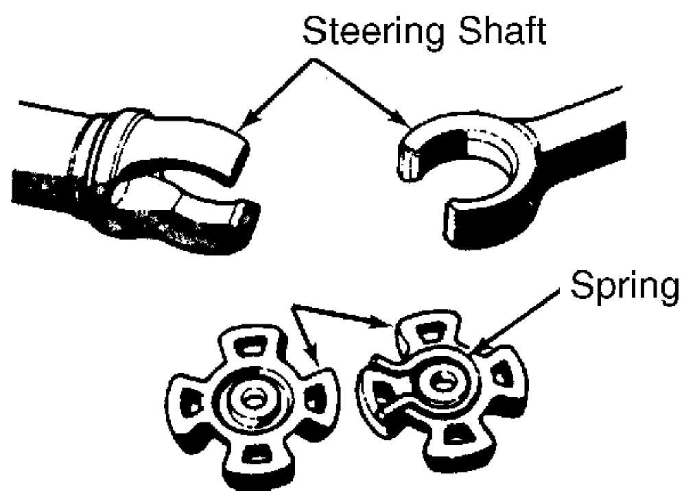
Centering Spheres
30258
Fig. 9: Shaft Centering Spheres
14) Using a screwdriver, remove shift tube retaining ring. Remove thrust washer. Remove 2 screws from lower bearing. Remove lower bearing from jacket. Using Puller (J-23073-01 for Jeep), remove shift tube from bowl. Insert bushing on end of puller in shift tube to force tube from bowl. DO NOT hammer shift tube as plastic joints may shear.
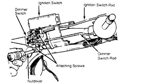
Fig. 10: Removing Shift Tube from Bowl on Models With Tilt Wheel
15) From lower end of jacket, remove shift tube from jacket. Remove jacket mounting plate by sliding from jacket notches and tipping down toward bowl hub at 12 o’clock position under jacket
opening. Remove wave washer. Remove bowl from jacket. Remove shift lever spring from bowl by winding spring up with pliers and pulling out.
By
removing spring retaining screw and moving spring
clockwise,
remove lock bolt spring. Using a hammer and punch, lightly
tap
drive shaft from sector. Remove drive shaft, sector and bolt.
Remove
rack, spring and shim (if used). Remove
tilt release lever pin.
Relieve
load on lever release by holding shoes inward.
Wedge a block
between top of shoes and bearing housing. Remove release
lever
and release lever spring. Using punch and hammer, remove lock
shoe
pin. Remove lock shoes and lock shoe springs.
Remove
bearings from bearing housing only if they are to
be replaced.
Remove separator and ball from bearing. Place housing on
work
bench. Using a punch against back surface of race, hammer race
from
housing. DO NOT reuse bearings.
Reassembly
1) During reassembly, coat all friction surfaces with
multipurpose grease. Clamp column in vise so that both ends of column are accessible. Install bearings in bearing housing (if removed).
Install
lock shoe springs, lock shoes and shoe pin in
bearing housing.
Use a .180" rod to line up shoes for
pin
installation. With tilt lever
opening on left side and with the shoes
facing up, the 4
slot shoe should also face up.
Install
spring, release lever and pin in bearing housing.
Install drive
shaft in housing. Lightly tap sector onto drive shaft
far enough
to bottom on shaft. Install lock bolt. Engage lock bolt
with
sector cam surface. Install rack and spring. Block tooth on
rack
should engage block tooth on sector.
Install
external tilt release lever. Install bolt spring
and spring
retaining screw. Tighten to 35 INCH lbs.
(4 N.m). Install
shift
lever spring in bowl by winding up with pliers and pushing in.
Slide
bowl into jacket. Install wave washer and jacket mounting plate.
Work
jacket mounting plate into jacket notches by tipping
jacket
mounting plate toward bowl hub at 12 o’clock
position and under
jacket opening. Slide jacket mounting plate in
jacket notches.
Carefully install shift
tube in lower end of jacket.
Align
key in tube with keyway in bowl. Using Puller (J-
23073-01
for Jeep), pull shift tube into bowl. See Fig.
11. DO NOT
push
or tap on end of shift tube. By pulling bowl up and compressing
wave
washer, install thrust washer and retaining pin.
Puller (C-4119 For Chrysler Motors, J-23073-01 For General Motors & Jeep)
30259
Fig. 11: Installing Shift Tube on Models With Tilt Wheel
7) Slide dimmer switch actuator rod through hole in support. Feed rod between bowl and jacket. Install support by aligning notch in support with notch in jacket. Insert 4 screws through support into
jacket mounting plate. Tighten screws to 60 INCH lbs. (7 N.m). Install lower bearing on lower end of jacket (if removed).
Install
centering spheres and anti-lash spring in upper
steering shaft.
Install lower steering shaft from same side of spheres
that
spring ends protrude. Perform a trial fit of assembly to ensure
that
master serration of upper shaft is on same side as master
serration
of lower shaft assembly.
Position
shift bowl fully counterclockwise. Install
ignition switch
actuator rod between bowl and jacket from bottom.
Guide back of
coupling into support slot. Assemble bearing housing
over
steering shaft. Engage rack over end of ignition switch
actuator
rod.
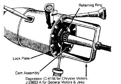
Fig. 12: Installing Lock Plate Retaining Ring
Position
access hole of bearing housing over end of
dimmer switch actuator
rod. Rotate housing counterclockwise to
assemble.
Holding lock shoes in disengaged position, assemble bearing
housing
over steering shaft until pivot holes line up with holes in
support.
Install
pivot pins. Assemble as far as possible, using
palm
pressure of hand to prevent enlarging support pivot hole. Using
a
small hammer and punch, tap pins into
place. Replace wiper/washer
pivot assembly. Press pivot pin in
cover (if removed). Check pivot
assembly
for ease of movement.
If
movement is restricted, tap other end of pin for
clearance.
Install wiper/washer switch. Replace tilt lever opening
shield
in cover (if removed). Position cap over
dimmer switch actuator
rod. Guide end of actuator rod into pivot
slot during cover assembly.
Hold cap so that cover will slide
over it.
Place
housing in full upward position. Ensure there is
grease between
guide and peg on support, tilt spring and tilt spring
retainer.
Install guide. Using a screwdriver in retaining slot, turn
retainer
clockwise to engage. Install bearing inner race and seat.
Install
lock housing cover. Tighten 3 screws to
100 INCH
lbs.
(11 N.m). Assemble
key warning switch to spring clip with formed
end
of clip under end of switch and with spring bowed away from
switch
on side opposite contact. Push
switch and spring into hole in lock
housing
cover with contacts facing lock cylinder bore.
Install
key light (if equipped). Install turn
signal
switch wires and connector
through cover, bearing housing and shift
bowl. Push in hazard
plunger. Install turn signal switch. Tighten
screws
to 25 INCH lbs. (3 N.m).
Install hazard warning knob and screw.
Pull
knob out.
Install
canceling cam spring, canceling cam (carrier
assembly) and lock
plate. Using Lock Plate Depressor (J-23653-A for
Jeep), depress
lock plate. See Fig. 12. Install a new
retaining ring.
Install tilt release lever (if removed).
Install turn signal switch
lever.
Install
ignition lock. Turn key to "LOCK" position.
Remove key.
Insert cylinder into housing far enough to contact shaft.
Press
inward while moving ignition switch actuator rod up and down
to
align parts.
When
parts align, cylinder will move inward and a spring
loaded
retainer will snap into place locking cylinder in housing.
To
replace ignition switch, position key cylinder in "LOCK"
position.
Remove key. Place ignition switch in "LOCK"
position (second detent
from bottom).
Fit
ignition switch actuator rod into slider hole.
Loosely install on
column with 2 screws. Push switch lightly
toward
lock housing to take out slack
in actuator rod. Tighten screws to 34
INCH
lbs. (4 N.m). DO
NOT move switch out of detent position.
Install
dimmer switch by firmly seating push rod into
switch.
Compress switch until 2 (.093") drill
bit shanks can be
inserted into
alignment holes. Reposition upper end of push rod in
pocket
of wiper/washer switch. Remove lower column cover (if
necessary).
With
a light upward pressure on switch, install 2 screws.
Remove
drill bits. Switch should click when lever is lifted and again
as
lever returns, just before it reaches lower stop. Install
wire
protector over wires on column jacket, being careful not to
pinch
wires.
Remove
column from vise. Position lower bracket assembly
on
steering column. Install 2 bolts. Tighten
to 105 INCH lbs. (12 N.
m).
Aligning master splines, install coupling
assembly on steering
shaft. Support coupling under joint. Drive
in roll pin.
NOTE: DO NOT remove bearings from housing unless they are to be
replaced. Install new bearings if bearings are removed from housing. Never reuse old bearings.
TORQUE SPECIFICATIONS
TORQUE SPECIFICATIONS TABLE
 Application Ft.
Lbs. (N.m)
Application Ft.
Lbs. (N.m)
Flexible Coupling Bolts 17 (23)
Steering Wheel Retaining Nut 45 (61)
Support Plate Bolts 17 (23)
INCH Lbs. (N.m)
Bearing Housing-to-Lock Housing Screws 35 (4)
Bracket-to-Column Bolt 124 (14)
Column Clamp Stud 20 (2)
Column Clamp Stud Nut 106 (12)
Hazard Switch 27 (3)
Housing Cover Screws 100 (11)
Ignition Switch Screws 35 (4)
Lock Housing-to-Jacket 90 (10)
Shift Tube Support Screws 60 (7)
Steering Column Lower Bracket Bolts 106 (12)
Tilt Release Spring Retaining Screw 35 (4)
Turn Signal Retaining Plate 27 (3)
Upper Bracket Nuts 106 (12)