4.0L 6-CYL -VIN [M] & 4.2L 6-CYL -VIN [C]
1988 Jeep Cherokee
1988 ENGINES
Chrysler Motors 4.0L & 4.2L 6-Cylinder
Jeep; Cherokee, Comanche, Wagoneer, Wrangler
ENGINE CODING
ENGINE IDENTIFICATION
NOTE: For engine repair procedures not covered in this article,
see ENGINE OVERHAUL PROCEDURES - GENERAL INFORMATION article
in the GENERAL INFORMATION section.
The Vehicle Identification Number (VIN) is located on upper
left side of dash and is visible through windshield. The fourth
character identifies the engine size. The tenth character identifies
the model year.
ENGINE IDENTIFICATION CODES TABLE
----------
Application
VIN Code
4.0L 6-Cylinder MPFI ........................
M
4.2L 6-Cylinder 2-Bbl. ......................
C
----------
SPECIAL ENGINE MARKS
Some engines are produced at factory with oversize or
undersize components. These engines are identified by a letter code
stamped on a boss between ignition coil and distributor. Letters are
decoded as follows:
*
"B" indicates all cylinder bores are .010" (.25 mm)
oversize.
*
"C" indicates all camshaft bearing bores are .010" (.25 mm)
oversize.
*
"M" indicates all main bearing journals are .010" (.25 mm)
undersize.
*
"P" indicates all connecting rod journals are .010" (.25 mm)
undersize.
REMOVAL & INSTALLATION
ENGINE REMOVAL
See ENGINE REMOVAL in this section.
INTAKE & EXHAUST MANIFOLD (4.0L)
WARNING: Fuel system is under pressure. Use care when removing fuel
lines to prevent personal injury.
Removal
1) Disconnect negative battery cable. Remove air inlet from
throttle plate assembly. Disconnect throttle, cruise control and
throttle valve (A/T models) cables (if equipped)
.
2) Disconnect and mark all vacuum and electrical connectors
from intake manifold. Disconnect fuel lines at fuel rail. Fuel lines
are removed by squeezing the 2 retaining tabs against the fuel line
and pulling the fuel line from the connector. Use caution as these
fuel lines are under pressure.
3) Loosen drive belt tensioner and remove drive belt. Remove
power steering pump and bracket from intake manifold. Remove fuel rail
retaining bolts. Remove fuel rail and injector assembly.
4) Remove intake manifold heat shield. Disconnect EGR tube
fittings. Disconnect exhaust pipe from manifold. Disconnect oxygen
sensor. Remove retaining bolts and remove manifolds.
Installation
1) Install new gasket. Install exhaust and intake manifolds
and loosely install bolts. Install EGR tube between manifolds. Tighten
manifold bolts in proper sequence see Fig. 1. Tighten to
specifications, see TORQUE SPECIFICATIONS TABLE in this article.
2) Tighten EGR tube bolts. Apply anti-seize to oxygen sensor
threads prior to installation. Reverse removal procedures for
remaining components. Tighten bolts to specification.
3) Install new "O" rings on fuel line connectors prior to
installation. Ensure "CLICK" sound is heard when installing fuel
lines. This indicates that fuel lines are properly seated.
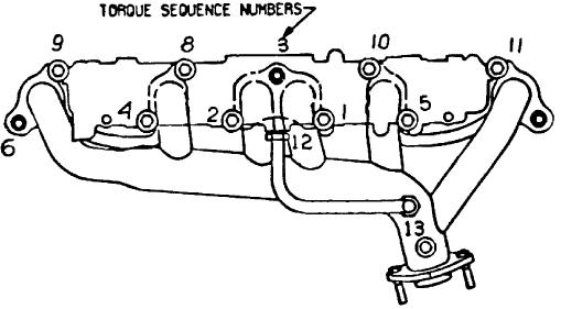
Fig. 1: Manifold Tightening Sequence (4.0L)
Courtesy of Chrysler Motors.
INTAKE & EXHAUST MANIFOLD (4.2L)
Removal
1) Remove air cleaner. Disconnect fuel line at carburetor.
Mark and disconnect all vacuum hoses, ventilation hoses and electrical
connectors at intake manifold.
2) Disconnect throttle cable at bellcrank. On A/T models,
disconnect throttle valve rod. On all models, remove PCV hose from
manifold. Drain cooling system. Remove coolant hoses from intake
manifold.
3) Remove EGR tube fittings from manifolds. Remove power
steering pump and A/C compressor and mounting brackets (if equipped)
.
4) Remove intake manifold bolts. Remove intake manifold. If
exhaust manifold requires removal, disconnect exhaust pipe from
manifold. Remove oxygen sensor (if equipped). Remove exhaust manifold.
Installation
1) Install new gasket. Install exhaust manifold and loosely
install bolts. Install intake manifold. Tighten bolts to specification
in proper sequence. See Fig. 2.
2) Apply anti-seize to oxygen sensor threads prior to
installation. Reverse removal procedure for remaining components.
Tighten bolts to specification. Fill and purge cooling system. See
COOLING SYSTEM AIR PURGE under WATER PUMP in this article.
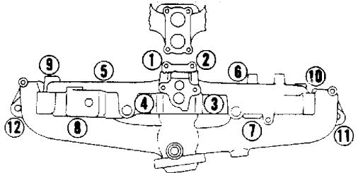
Fig. 2: Manifold Tightening Sequence (4.2L)
Courtesy of Chrysler Motors.
CYLINDER HEAD
Removal
1) Disconnect negative battery cable. Drain cooling system.
Disconnect hoses at thermostat housing. Remove intake and exhaust
manifolds. See the following:
* INTAKE & EXHAUST MANIFOLD (4.0L)
.
* INTAKE & EXHAUST MANIFOLD (4.2L)
.
2) Disconnect and mark all hoses and electrical connections
at cylinder head. Disconnect and mark spark plug wires. Remove spark
plugs. Remove valve cover bolts.
3) Remove the rocker arms and the push rods. Remove cylinder
head bolts. Remove cylinder head. See ROCKER ARMS & BRIDGE.
Inspection
Inspect cylinder head for cracks or damage. Using
straightedge, check cylinder head for warpage in several areas. Repair
or replace cylinder head if warpage exceeds .002" (.05 mm) per each 6"
(152 mm) or damage exists.
Installation
1) Ensure all gasket surfaces are clean. Clean carbon from
combustion chambers and tops of pistons. Apply sealant to both sides
of new cylinder head gasket. Install new gasket with the word "TOP"
upward. Ensure all holes are aligned.
2) Install cylinder head. Apply sealing compound to threads
of cylinder head bolt No. 11 prior to installation. See Fig. 3.
Install head bolts.
3) Tighten all bolts in sequence (except No. 11) to 110 ft.
lbs. (149 N.m) on 4.0L or 85 ft. lbs. (115 N.m) on 4.2L models.
Tighten No. 11 head bolt to 100 ft. lbs. (136 N.m) on 4.0L or 75 ft.
lbs. (136 N.m) on 4.2L. See Fig. 3.
4) Reverse removal procedure for remaining components.
Install valve cover and new gasket. Tighten bolts to specification.
5) Refill and purge cooling system. See COOLING SYSTEM AIR
PURGE under WATER PUMP in this article.
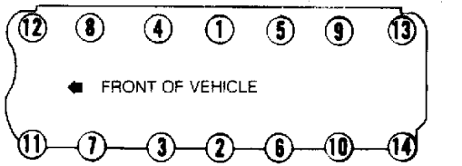
Fig. 3: Cylinder Head Bolt Tightening Sequence
Courtesy of Chrysler Motors.
Valve Arrangement
E-I-I-E-I-E-E-I-E-I-I-E (Front-to-rear)
.
ROCKER ARMS & BRIDGE
Removal
1) Remove PCV valve hose at valve cover. Remove cruise
control servo (if equipped). Remove valve cover. Alternately loosen
each rocker arm bolt one turn at a time.
2) Remove rocker arm assemblies and push rods. Mark
components for reassembly. Components must be installed in original
location.
Installation
Reverse removal procedure. Install rocker arm components in
original location. Install valve cover and new gasket. Tighten bolts
to specification.
Valve Guide
Valve guides are not replaceable. If clearance is excessive,
valve guides must be reamed to accommodate oversized stem valves.
VALVE SPRING
Valve springs can be removed without removing cylinder head.
Valve Spring Installed
For 4.0L the Valve Spring Installed Height Specification is
1.625 inches or 41.29 mm. For the 4.2L the information is not
available from manufacturer.
HYDRAULIC VALVE LIFTER
Removal
Remove cylinder head. See CYLINDER HEAD. Using Lifter
Remover/Installer (J-21884), remove lifter. Mark lifter location for
reassembly reference. Replace lifters as an assembly if damaged.
Internal components cannot be interchanged.
Inspection
Inspect lifter and camshaft mating surfaces for wear. Check
cylinder block lifter bore diameter. Lifter bore diameter should be
within .9055-.9065" (22.999-23.025 mm). Replace parts as necessary.
Installation
Soak lifter assembly in engine oil prior to installation.
Reverse removal procedure for installation. Install lifter in original
location.
ENGINE FRONT COVER
Removal
1) Disconnect negative battery cable. Remove drive belts, fan
and hub assembly. Remove pulley from vibration damper. Remove
vibration damper retaining bolt and washer.
2) Using Puller (J-21719-01), remove vibration damper and
key. Remove alternator and A/C compressor bracket (if equipped)
.
Remove oil pan-to-front cover bolts. Remove cover-to-block retaining
bolts. Remove front cover.
3) Cut oil pan gasket tabs even with face of cylinder block.
Remove tabs. Remove gasket from oil pan. Pry crankshaft oil seal from
cover.
Installation
1) Ensure all gasket surfaces are clean. Ensure oil slinger
is installed on crankshaft. Apply sealing compound on both sides of
front cover gasket. Install gasket on cylinder block. Replace front
section of oil pan seal with similar section fabricated from new seal.
2) Coat seal with RTV sealant and place in position. Apply
sealant to the joint area of oil pan and cylinder block. Apply engine
oil on seal-to-oil pan contact areas.
3) Place front cover on cylinder block. Place Front Cover
Seal Installer (J-22248) in front cover seal area. Install all
retaining bolts. Tighten bolts to specification.
4) Install front cover oil seal. See FRONT COVER OIL SEAL in
this article. Remove front cover seal installer. Reverse removal
procedure for remaining components. Lubricate vibration damper
retaining bolt with oil prior to installation. Tighten bolts to
specification.
FRONT COVER OIL SEAL
1) Remove vibration damper. Pry seal from front cover. Use
care not to damage seal area. Position new seal on Front Cover Seal
Installer (J-22248) with lip facing outward.
2) Apply sealant to seal outer diameter. Lightly coat
crankshaft with oil. Place front cover seal installer on front of
crankshaft. Tap seal into front cover. Lightly coat seal contact area
of vibration damper with oil.
3) Install key in crankshaft (if removed). Install vibration
damper. Lubricate vibration damper bolt with oil. Install retaining
bolt and washer. Tighten to specification.
TIMING CHAIN & SPROCKET
Removal
1) Drain cooling system. Remove radiator. Remove engine front
cover. See ENGINE FRONT COVER in this article. Remove oil slinger.
Rotate crankshaft until timing marks on sprockets are aligned. See
Fig. 4.
2) Remove camshaft sprocket bolt. Remove timing chain and
both sprockets as an assembly.
Installation
Install timing chain and sprockets. Ensure timing marks are
aligned. See Fig. 4. Install camshaft sprocket bolt. Tighten bolts to
specification. Install new front cover oil seal. Reverse removal
procedure for remaining components.
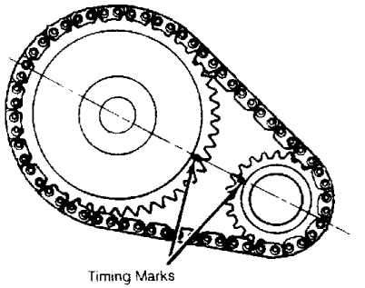
Fig. 4: Timing Chain & Sprocket Alignment
Courtesy of Chrysler Motors.
CAMSHAFT
Removal
1) Drain cooling system. Remove radiator. Discharge A/
C
system if necessary. Remove A/C condenser and receiver assembly (if
equipped). Remove fuel pump (if equipped with mechanical pump)
,
ignition wires and distributor.
2) Remove cylinder head. See CYLINDER HEAD in this article.
Remove hydraulic lifters. Using Lifter Remover/Installer (J-21884)
,
remove lifters. Mark lifter location for reassembly reference.
3) Remove engine front cover. See ENGINE FRONT COVER in this
article. Remove timing chain and sprockets. Remove front bumper and
grille (if necessary). Carefully remove camshaft.
Inspection
Inspect camshaft for flaking, lobe wear or worn bearing
journals. Replace if not within specification. See ENGINE
SPECIFICATIONS tables.
Installation
Lubricate camshaft and install into place. Use care not to
damage camshaft bearings. Reverse removal procedure to complete
installation. Tighten bolts to specification.
Camshaft Bearing
Replace camshaft bearings using camshaft bearing
remover/installer. Ensure oil holes are aligned after installation.
OIL PAN
See OIL PAN REMOVAL at end of ENGINE section.
PISTON & ROD
NOTE:
Mark piston cylinder location for reassembly reference.
Install pistons in original cylinder location.
Removal
1) Remove cylinder head. See CYLINDER HEAD in this article.
Remove oil pan. See OIL PAN REMOVAL at end of ENGINE section. Remove
ridge or deposits from cylinder bore.
2) Mark connecting rod and piston for cylinder
identification. Remove bearing cap. Remove piston and rod assembly.
CAUTION: Arrows on top of piston must point toward front of engine.
Oil squirt holes in connecting rod must face camshaft side
of engine.
Installation
1) Ensure ring end gap and side clearance are within
specification. See ENGINE SPECIFICATIONS tables. Install rings on
piston. Position ring end gaps at specified areas. See Fig. 5. Ring
gaps may vary 20 degrees from positions illustrated.
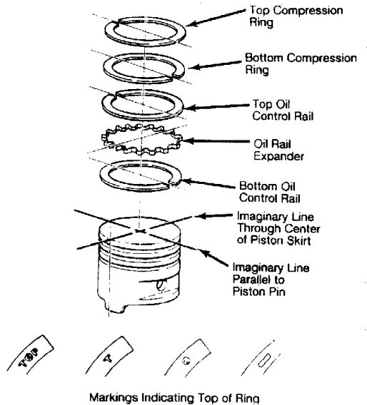
Fig. 5: Positioning Piston Ring Gaps
Courtesy of Chrysler Motors
2) Lubricate piston assembly and cylinder block. Install
piston assembly. Arrows on top of piston must face toward front of
engine and connecting rod oil squirt hole should face camshaft side of
engine.
3) Install bearings. Check oil clearance and connecting rod
side play clearance. Reverse removal procedure for remaining
components. Tighten bolts to specification.
Fitting Pistons
1) Determine cylinder taper, wear and out-of-roundness and
piston clearance. For cylinder specifications, see CYLINDER, PISTON
&
ROD SPECIFICATIONS table. If taper or out-of-roundness are not within
specification, hone or bore cylinders for installation of new pistons.
2) Measure piston at right angle of the piston pin at the
center line of the pin. Compare reading to cylinder bore to determine
clearance. Mark fitted piston for cylinder location.
CYLINDER, PISTON & ROD SPECIFICATIONS TABLE
----------
Application In. (mm)
Connecting Rod
Crankshaft Bore ................ 2.2080-2.2085 (56.083-56.095)
Pin Bore ......................... .9288-.9298 (23.591-23.616)
Cylinder Bore
Diameter
4.0L ......................... 3.8751-3.8775 (98.427-98.488)
4.2L ......................... 3.7501-3.7533 (95.252-95.334)
Out-of-Round ...................................... .001 (.02)
Taper ............................................. .001 (.02)
Piston Pin Bore Diameter ........... .9308-.9313 (23.642-23.655)
Piston Pin Diameter ................ .9304-.9309 (23.632-23.644)
Piston-to-Cylinder Clearance ..... .0009-.0017 (.022-.043)
----------
PISTON PIN
NOTE:
Note direction of arrows on piston and oil squirt hole in
connecting rod location prior to removal.
Removal
Position piston on Support (J-21872-1), Pin Pilot (J-21872-2)
and Driver (J-21872-3) on an arbor press. See Fig. 6. Note location of
piston pin through gauge window. Press piston pin from piston.
NOTE:
Piston and pin must be at standard room temperature when
measuring fit. Piston pin should gravity-fall through the
piston at room temperature. Piston pin cannot be reused
after removal.
Inspection
Measure piston pin diameter, piston bore and connecting rod
bores. Replace components if not within specification. See CYLINDER,
PISTON & ROD SPECIFICATIONS table.
NOTE:
Rod must be positioned on the piston so the oil squirt hole
faces the camshaft side of the engine when piston is
installed with arrow toward the front of the engine.
Installation
1) Insert pin pilot through piston and connecting rod. Place
assembly on support. Insert piston pin through the upper piston pin
bore and into connecting rod pin bore. See Fig. 6.
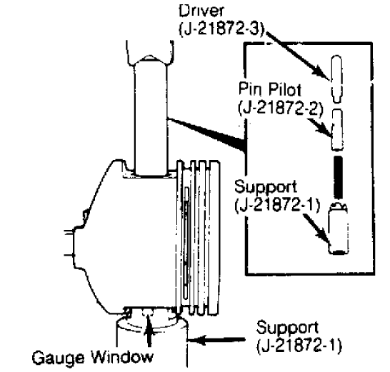
Fig. 6: Piston Pin Removal & Installation
Courtesy of Chrysler Motors.
2) Position driver inside pin. Using arbor press, press pin
through rod and piston bores until pilot indexes with mark on support.
Remove piston and connecting rod. Pin should be centered in rod
.
0312" (.792 mm)
.
3) Piston pin installation requires a 2000 lb. (906 kg) press
fit. Replace connecting rod if noticeably less effort is encountered.
ROD BEARING
NOTE:
Crankshaft journal diameters are indicated by a color coded
mark placed on the adjacent counterweight or cheek toward
the flanged (rear) end of crankshaft. Note color code to
determine proper bearing usage. Check oil clearance after
bearing installation.
Removal
Remove oil pan. See OIL PAN REMOVAL at end of ENGINE section.
Rotate crankshaft to position rod to be serviced at bottom of stroke.
Mark bearing cap and connecting rod. Remove bearing cap with bearing.
Push piston and rod assembly up to remove upper bearing.
Installation
1) Note color code on edge of bearings removed. Install
bearings. Using Plastigage method, check bearing clearances. Replace
bearings as necessary to obtain correct clearance. Bearings are
available in standard and undersize application.
2) If required, different sized upper and lower bearings may
be installed to obtain correct oil clearance. Tighten bolts to
specification. Check rod side play. Rotate crankshaft to ensure
freedom of movement. Reverse removal procedure for remaining
components. Tighten bolts to specification.
NOTE:
Avoid combining bearing inserts in excess of .001" (.02 mm)
difference in size.
MAIN BEARING
Removal
Remove oil pan. See OIL PAN REMOVAL at end of ENGINE section.
Ensure main bearing caps are marked for location. Remove bearing cap.
Rotate crankshaft to remove bearings. Note color code on edge of
bearing.
NOTE:
Crankshaft main bearing journal diameters are indicated by
a
color code. Color code is placed on the adjacent cheek
toward the flanged (rear) end of crankshaft for all except
the rear main. Rear main is color coded on the rear flange.
Note color code to determine proper bearing usage. Check oil
clearance after bearing installation.
Installation
1) Note color code on edge of bearings removed. Install
bearings. Ensure caps are installed in original location with arrow on
cap facing toward front of engine. Using Plastigage method, check
bearing clearances.
2) Replace bearings as necessary to obtain correct clearance.
Bearings are available in standard and undersize applications. If
required, different sized upper and lower bearings may be installed to
obtain correct oil clearance.
NOTE:
If different sized bearings are used, odd sized bearings must
all be uniform in location (upper or lower). DO NOT use
bearings with a thickness difference exceeding
.001" (.02 mm)
.
3) Tighten bolts to specification. Check crankshaft end play.
See CRANKSHAFT END PLAY in this article. Rotate crankshaft to ensure
freedom of movement. Reverse removal procedure for remaining
components. Tighten bolts to specification.
Crankshaft End Play
1) Using dial indicator, check crankshaft end play. Inspect
crankshaft thrust surfaces or thrust bearing for wear if not within
specification. See ENGINE SPECIFICATIONS table.
2) Replace thrust bearing if required. When replacing thrust
bearing, pry crankshaft forward then reward prior to tightening main
bearing cap to specification. Recheck end play. Replace crankshaft if
not within specification.
REAR MAIN OIL SEAL
Removal
1) Remove oil pan. See OIL PAN REMOVAL in this section.
Remove rear main bearing cap. Note direction of seal lip installation.
Remove seal from bearing cap. Loosen all remaining main bearing cap
bolts.
2) Using a brass drift, tap upper seal around crankshaft
until seal protrudes enough to permit removal with pliers. Remove
seal.
Installation
1) Clean crankshaft seal surface. Coat seal-to-block contact
areas with liquid soap. Lightly coat all seal lips with engine oil.
See Fig. 7. Install upper seal into block with lip facing toward front
of engine.
2) Apply Silicone sealer on both sides of lower seal tabs.
Ensure no sealer is applied on seal lip. Apply liquid soap on seal-to
cap contact surfaces.
3) Install lower seal into bearing cap with lip facing toward
front of engine. Ensure seal is firmly seated in bearing cap. Apply
Silicone sealer to chamfered edges of bearing cap. See Fig. 7.
CAUTION: DO NOT apply Silicone sealer on cap-to-block contact
surfaces. Sealer should only be applied to chamfered edges
only.
4) Install rear main bearing cap. Tighten main bearing cap
bolts to specification.

Fig. 7: Installing Rear Main Bearing Oil Seal
Courtesy of Chrysler Motors.
WATER PUMP
Removal
Drain cooling system. Disconnect radiator and heater hoses
from pump. Remove drive belt(s). Remove fan shroud. Remove fan
assembly. Remove electric cooling fan (if equipped). Remove power
steering bracket from water pump. Remove water pump and gasket.
Installation
Ensure gasket surfaces are clean. Install water pump. Tighten
bolts to specification. Ensure pump turns freely. Reverse removal
procedures. Fill and purge air from cooling system.
NOTE:
It may be necessary to remove heater hose to remove trapped
air if system cannot be purged using following procedures.
Cooling System Air Purge (Vehicles W/Coolant Recovery)
Fill system to proper level. Place heater control to "HEAT"
position and temperature control to "WARM" or "HIGH" position. Install
coolant caps. Operate engine to normal operating temperature. Shut off
engine and allow system to cool. Add coolant to recovery bottle.
Repeat procedure to obtain correct coolant level.
Cooling System Air Purge (Vehicles W/O Coolant Recovery)
Fill system to proper level. Place heater control to "HEAT"
position and temperature control to "WARM" or "HIGH" position. Operate
engine to normal operating temperature with radiator cap removed. Add
necessary coolant and install radiator cap.
NOTE:
For further information on cooling systems, see appropriate
article in the ENGINE COOLING section.
LUBRICATION
CRANKCASE CAPACITY
Crankcase capacity for 4.0L is 5 1/2 qts. (5.2L) or 5 qts.
(4.7L) for 4.2L with oil filter change.
NORMAL OIL PRESSURE
.
Normal oil pressure should be 37-75 psi (2.6-5.3 kg/cm
)
maximum above 1600 RPM. Minimum oil pressure should be 13 psi (.
9
.
kg/cm ) at 600 RPM.
OIL PRESSURE REGULATOR VALVE
Oil pressure regulator valve is located in pump body. Valve
is nonadjustable and serviced as an assembly.
ENGINE OILING SYSTEM
Engine lubrication is provided by the distributor driven
gear-type oil pump. Oil is supplied through the full-flow oil filter
and into an internal oil passage. Internal passage provides oil to the
lifter bores. Oil is then routed to camshaft and crankshaft bearings.
Oil is supplied to rocker arms from the hydraulic lifters and through
the push rods.
OIL PUMP
Removal
Remove oil pan. See OIL PAN REMOVAL in this section. Remove
oil pump retaining bolts.
CAUTION: DO NOT move oil pick-up pipe in pump body. If oil pick-up
pipe is moved, pick-up pipe must be replaced to ensure an
airtight seal.
Disassembly & Inspection
1) Disassemble pump. See Fig. 8. Use feeler gauge and
straightedge to check gear end clearance. Place straightedge across
gears and pump body. Using feeler gauge, determine thickness feeler
gauge which fits snugly between straightedge and gears.
2) With gears installed in pump body, insert feeler gauge
between gear tooth and inner wall of pump body to check gear-to-body
clearance. Rotate gears and measure clearance at each gear tooth.
3) Compare measurements to specification. See OIL PUMP
SPECIFICATIONS table. Repair as necessary if not within
specifications. Check pressure regulator valve for wear or binding in
pump body. Replace components if wear or binding exists.
OIL PUMP SPECIFICATIONS TABLE
----------
Application In. (mm)
Gear End Clearance ........... .004-.008 (.10-.20)
Gear-to-Body Clearance ....... .002-.004 (.05-.10)
----------
CAUTION: If pressure regulator valve is replaced, ensure replacement
valve is the same diameter as that removed. Different
diameter valves may be used.
Reassembly & Installation
1) Reverse procedures for reassembly and installation. Apply
Permatex No. 2 to pick-up pipe prior to installation. Using Pipe
Installer (J-21882), install pick-up pipe. Ensure pick-up pipe support
bracket is aligned with pump cover bolt.
2) Fill gear cavity with petroleum jelly prior to installing
cover. Apply Loctite on pump cover area. Install cover and bolts.
Tighten bolts to specification. Check pump gears for freedom of
rotation.
3) Install oil pump and new gasket. Tighten retaining bolts
to specification.
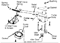
Fig. 8: Exploded View of Oil Pump Assembly
Courtesy of Chrysler Motors.
TORQUE SPECIFICATIONS TABLE
TORQUE SPECIFICATIONS TABLE
----------
Application Ft. Lbs. (N.m)
Camshaft Sprocket Bolt .......................... 80 (109)
Connecting Rod Cap Nut ........................... 33 (45)
Crankshaft Pulley-to-Damper Bolt ................. 20 (27)
Cylinder Head Bolt
4.0L
No. 11 .................................... 100 (135)
All Others ................................. 110 (149)
4.2L
No. 11 ..................................... 75 (102)
All Others .................................. 85 (115)
Exhaust Pipe-to-Manifold Bolt .................... 20 (27)
Fan & Hub Bolt ................................... 18 (24)
Flywheel-to-Crankshaft Bolt .................... 105 (142)
Fuel Rail Bolt ................................... 20 (27)
Intake & Exhaust Manifold Bolt
4.0L
Exhaust Manifold Bolts 1-5 ................... 23 (31)
Exhaust Manifold Bolts 6-7 .................. 17 (23)
Exhaust Manifold Bolts 8-11 ................. 23 (31)
Exhaust Manifold Bolts 12-13 ................ 30 (41)
4.2L ........................................... 23 (31)
Main Bearing Cap Bolt
Step 1 ......................................... 40 (54)
Step 2 ......................................... 70 (95)
Step 3 ........................................ 80 (109)
Oil Pump Attaching Bolt
Short .......................................... 10 (14)
Long ........................................... 17 (23)
Oxygen Sensor .................................... 35 (47)
Rocker Arm Bolt .................................. 19 (26)
Vibration Damper Bolt ....................... (1) 80 (109)
Water Pump Bolts ................................. 13 (18)
INCH Lbs. (N.m)
Engine Front Cover
Bolt ............................................ 60 (7)
Studs ......................................... 192 (22)
Oil Pan Bolt
1/4" X 20 ....................................... 84 (9)
5/16" X 18 .................................... 132 (15)
Oil Pump Cover Bolt ............................... 70 (8)
Valve Cover Bolt .................................. 55 (5)
(1) - Clean and lubricate with oil prior to tightening.
----------
ENGINE SPECIFICATIONS
GENERAL ENGINE SPECIFICATIONS
GENERAL SPECIFICATIONS TABLE
----------
Application In. (mm)
4.0L
Displacement
Cu. In. .......................................... 242
Liters ........................................... 4.0
Fuel System ........................................ MPI
HP@RPM ...................................... 173 @ 2500
Torque Ft. Lbs.@RPM ......................... 220 @ 2500
Compression Ratio ................................ 9.2:
1
Bore ....................................... 3.88 (98.4)
Stroke ..................................... 3.44 (87.4)
4.2L
Displacement
Cu. In. .......................................... 258
Liters ........................................... 4.2
Fuel System ..................................... 2-Bbl.
HP@RPM ...................................... 112 @ 3000
Torque Ft. Lbs.@RPM ......................... 210 @ 2000
Compression Ratio ................................ 9.2:
1
Bore ....................................... 3.75 (95.3)
Stroke ..................................... 3.90 (98.9)
----------
VALVE SPECIFICATIONS
VALVES SPECIFICATIONS TABLE
----------
Application In. (mm)
4.0L
Intake
Head Diameter ........................... 1.91 (48.51).
Face Angle ....................................... 45 .
Seat Angle ..................................... 44.5
Seat Width ..................... .040-.060 (1.02-1.52)
Stem Diameter ............................ .312 (7.92)
Stem Clearance ................... .001-.003 (.03-.08)
Valve Lift .............................. .424 (10.76)
Exhaust
Head Diameter ........................... 1.50 (38.10).
Face Angle ....................................... 45 .
Seat Angle ..................................... 44.5
Seat Width ..................... .040-.060 (1.02-1.52)
Stem Diameter ............................ .312 (7.92)
Stem Clearance .................. .001-.003 (.03-.003)
Valve Lift .............................. .424 (10.76)
Valve Spring Height Installed ............ 1.625 (41.29)
4.2L
Intake
Head Diameter .................. 1.78-1.79 (45.3-45.5).
Face Angle ....................................... 29 .
Seat Angle ....................................... 30
Seat Width ..................... .040-.060 (1.02-1.52)
Stem Diameter ................ .3715-.3725 (9.44-9.46)
Stem Clearance ................... .001-.003 (.03-.08)
Valve Lift .............................. .405 (10.29)
Exhaust
Head Diameter .................. 1.40-1.41 (35.6-35.8).
Face Angle ....................................... 44 .
Seat Angle ..................................... 44.5
Seat Width ..................... .040-.060 (1.02-1.52)
Stem Diameter ................ .3715-.3725 (9.44-9.46)
Stem Clearance ................... .001-.003 (.03-.08)
Valve Lift .............................. .405 (10.29)
Valve Spring Height Installed ...................... (1)
(1) - Specification not provided from manufacturer.
----------
PISTON/PIN/RING SPECIFICATIONS
PISTONS, PINS & RINGS TABLE
----------
Application In. (mm)
Piston Clearance
Pins
Piston Fit
.................
.....................
.0009-.0017 (.023-.043)
.0003-.0005 (.008-.013)
Rod Fit ...................................... Press Fit
Rings
Ring No. 1 & No.
2
End Gap .......................... .010-.020 (.25-.51)
Side Clearance ............... .0017-.0032 (.043-.081)
Ring No.
3
End Gap .......................... .010-.025 (.25-.64)
Side Clearance .................. .001-.008 (.03-.020)
----------
BEARING SPECIFICATIONS
CRANKSHAFT MAIN & CONNECTING ROD BEARINGS TABLE
----------
Application In. (mm)
Main Bearings
Journal Diameter ........... 2.4996-2.5001 (63.49-63.50)
Clearance ....................... .0010-.0025 (.03-.064)
Thrust Bearing ................................... No.
3
Crankshaft End Play ............ .0015-.0065 (.038-1.65)
Connecting Rod Bearings
Journal Diameter ........... 2.0934-2.0955 (53.17-53.23)
Clearance .......................... .001-.003 (.03-.08)
Side Play .......................... .010-.019 (.25-.48)
----------
CAMSHAFT SPECIFICATIONS
CAMSHAFT TABLE
----------
Application In. (mm)
Clearance ............................ .001-.003 (.03-.08)
Lobe Lift .................................... .253 (6.43)
Journal Diameter
No. 1 ........................ 2.029-2.030 (51.54-51.56)
No. 2 ........................ 2.019-2.020 (51.28-51.31)
No. 3 ........................ 2.009-2.010 (51.03-51.05)
No. 4 ........................ 1.999-2.000 (50.77-50.80)
----------
VALVE SPRING SPECIFICATIONS
VALVE SPRINGS TABLE
----------
Application In. (mm)
4.0L
Pressure (1)
Valve Closed ............ 66-74 @ 1.625 (30-34 @ 45.5)
Valve Open ........... 205-220 @ 1.20 (91-100 @ 30.48)
Free Length ............................... 1.82 (46.23)
4.2L
Pressure (1)
Valve Closed ............. 64-72 @ 1.79 (29-33 @ 45.5)
Valve Open ............. 188-202 @ 1.41 (85-92 @ 35.8)
Free Length ................................ 1.99 (50.5)
(1) - Lbs. @ In. (Kg @ mm)
.
----------
