WHEEL ALIGNMENT THEORY/OPERATION
1988 Jeep Cherokee
GENERAL INFORMATION
Wheel Alignment Theory & Operation
ALL MODELS
* PLEASE READ THIS FIRST *
NOTE: This article is intended for general information purposes
only. This information may not apply to all makes and models.
PRE-ALIGNMENT INSTRUCTIONS
GENERAL ALIGNMENT CHECKS
Before adjusting wheel alignment, check the following:
Each axle
uses tires of same construction and tread style,
equal in tread
wear and overall diameter. Verify that radial
and axial runout is
not excessive. Inflation should be at
manufacturer’s
specifications.
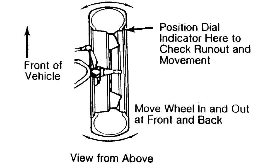
Steering
linkage and suspension must not have excessive play.
Check
for wear in tie rod ends and ball joints. Springs must
not be
sagging. Control arm and strut rod bushings must not
have
excessive play. See Fig. 1.
266Ý4
Fig. 1: Checking Steering Linkage
* Vehicle must be on level floor with full fuel tank, no passenger load, spare tire in place and no load in trunk. Bounce front and rear end of vehicle several times. Confirm
vehicle is at normal riding height.
Steering
wheel must be centered with wheels in straight ahead
position.
If required, shorten one tie rod adjusting sleeve
and lengthen
opposite sleeve (equal amount of turns). See
Fig.
2.
Wheel
bearings should have the correct preload and lug nuts
must be
tightened to manufacturer’s specifications. Adjust
camber, caster
and toe-in using this sequence. Follow
instructions of the
alignment equipment manufacturer.
CAUTION: Do not attempt to correct alignment by straightening parts. Damaged parts must be replaced.
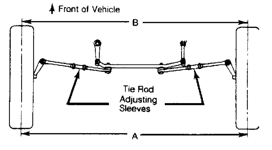
26695
Fig. 2: Adjusting Tie Rod Sleeves (Top View)
CAMBER
Camber
is the tilting of the wheel, outward at either top
or
bottom, as viewed from front of vehicle. See Fig. 3.
When
wheels tilts outward at the top (from centerline of
vehicle),
camber is positive. When wheels tilt inward at top, camber
is
negative. Amount of tilt is measured in degrees from vertical.
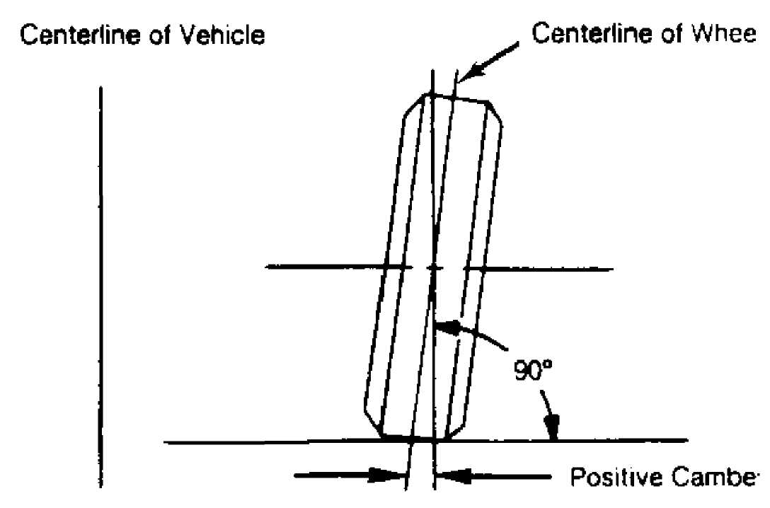
26696
Determining Camber Angle
Fig. 3:
CASTER
Caster
is tilting of front steering axis either forward or
backward
from vertical, as viewed from side of vehicle. See Fig. 4.
When
axis is tilted backward from vertical, caster is
positive.
This creates a trailing action on front wheels. When axis is
tilted
forward, caster is negative, causing a leading action on
front
wheels.
Vertical Centerline of Wheel
Positive Direction
26697
Fig. 4: Determining Caster Angle
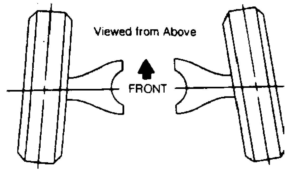
TOE-IN ADJUSTMENT
Toe-in is the width measured at the rear of the tires
subtracted by the width measured at the front of the tires at about spindle height. A positive figure would indicate toe-in and a negative figure would indicate toe-out. If the distance between the front and rear of the tires is the same, toe measurement would be zero. To adjust:
1) Measure toe-in with front wheels in straight ahead
position and steering wheel centered. To adjust toe-in, loosen clamps and turn adjusting sleeve or adjustable end on right and left tie rods. See Figs. 2 and 5.
2) Turn
equally and in opposite directions to maintain
steering wheel in
centered position. Face of tie rod end must be
parallel
with machined surface of steering rod end to prevent binding.
3) When tightening clamps, make certain that clamp bolts are positioned so there will be no interference with other parts throughout the entire travel of linkage.
26698
Fig. 5: Wheel Toe-In (Dimension A Less Dimension B)
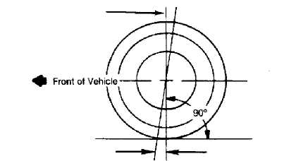
TOE-OUT ON TURNS
Toe-out
on turns (turning radius) is a check for bent or
damaged
parts, and not a service adjustment. With caster, camber, and
toe-in
properly adjusted, check toe-out with weight of vehicle on
wheels.
Use a full
floating turntable under each wheel, repeating
test with each
wheel positioned for right and left turns. Incorrect
toe-out
generally indicates a bent steering arm. Replace arm, if
necessary,
and recheck wheel alignment.
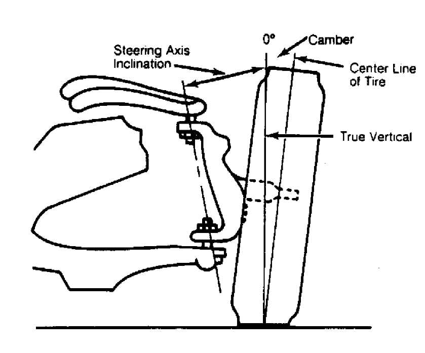
STEERING AXIS INCLINATION
Fig. 6: Checking Steering Axis Inclination
Steering
axis inclination is a check for bent or damaged
parts,
and not a service adjustment. Vehicle must be level and
camber
should be properly adjusted. See
Fig. 6.
If camber
cannot be brought within limits and steering
axis inclination is
correct, steering knuckle is bent. If camber and
steering axis
inclination are both incorrect by approximately the same
amount,
the upper and lower control arms are bent.