POWER STEERING PUMP
1988 Jeep Cherokee
1988 STEERING
Jeep Power Steering Pumps - Saginaw Vane-Type
Cherokee, Comanche, Grand Wagoneer, Pickup, Wagoneer, Wrangler
DESCRIPTION
Saginaw vane-type power steering pump can be identified by "ham-shaped" fluid reservoir can. Rectangular pumping vanes carried by a shaft driven rotor move fluid from intake to pressure cavities of cam ring.
Centrifugal force throws vanes against inside surface of cam ring to pick up residual oil. As more oil is picked up, it is forced into cavities of thrust plate, into 2 cross-over holes in cam ring and pressure plate and into a high pressure area between pressure plate and housing end plate.
Filling the high pressure area causes oil to flow under vanes in slots of rotor. This forces vanes to follow inside oval surface of cam ring. As vanes rotate to small area of cam ring, oil is forced out from between vanes.
TROUBLE SHOOTING
Refer to TROUBLE SHOOTING - BASIC PROCEDURES article in the GENERAL TROUBLE SHOOTING section.
LUBRICATION & TESTING
See POWER STEERING GENERAL SERVICING article in the STEERING section.
REMOVAL & INSTALLATION
POWER STEERING PUMP
Removal & Installation
Loosen
pump adjusting bolt (or nut) and pump mounting
bolts. Remove pump
drive belt. Disconnect pressure and return hoses
from pump. Cap
ends to prevent loss of fluid or contamination.
Remove
pump bracket-to-engine bolts. Remove pump, pulley
and mounting
bracket as an assembly. To install, reverse removal
procedure.
Bleed system.
OVERHAUL
CAUTION: When clamping pump in vise, be careful not to exert
excessive force on front hub or pump. DO NOT use hammer to remove pulley.
DISASSEMBLY
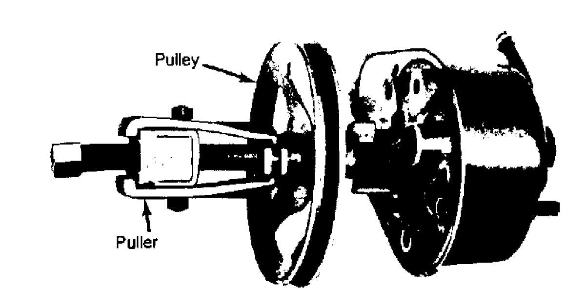
1) Drain pump reservoir. Clean exterior of unit. Remove mounting bracket(s). Using a puller, withdraw pulley from shaft. See Fig. 1.
30342
Fig. 1: Removing Pump Pulley
Clamp
pump, with shaft pointing down and at the square
boss of the
shaft housing, into a soft-jawed vise. Remove pressure
line union
and "O" ring. Remove reservoir
retaining studs.
Tap
against filler tube with plastic hammer to loosen
reservoir
on pump body. Remove reservoir from body. Remove and discard
"O"
rings.
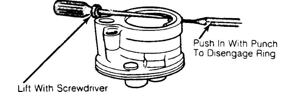
Using
1/8" punch, tap end plate retaining
ring around
until end of ring is near
hole in pump body. Inserting punch in hole,
disengage ring from
groove in pump bore. Using a screwdriver, pry ring
from
body. See Fig. 2.
30341
Fig. 2: Removing Pump End Plate Retaining Ring
Tap end
plate with a soft-faced hammer to loosen. Spring
tension should
push plate up. Remove spring. Remove pump from vise.
Invert pump and place on flat surface. Using soft-faced
hammer, tap end of drive shaft to loosen pressure plate, rotor, and thrust plate assembly from body.
Lift
pump body off rotor assembly. Flow control valve and
spring
should slide out of bore. Remove and discard end plate and
pressure
plate "O" rings.
Using a
screwdriver, pry drive shaft oil seal from body.
Lift pressure
plate and cam ring from rotor. Remove rotor vanes.
Clamp
drive shaft in soft-jawed vise, with rotor and
thrust plate
facing up. Remove rotor lock ring from shaft. Use care
not to
nick shaft or rotor. Slide rotor and thrust plate off shaft.
Remove
shaft from vise.
CLEANING & INSPECTION
Clean all
pump components (except drive shaft seal) in
clean solvent. Blow
dry. Inspect flow control valve assembly for wear,
scoring, burrs
or other damage. Inspect seal bore for burrs, nicks, or
score
marks that would allow oil to by-pass outer seal surface.
Check
all machined surfaces of body for scratches or burrs
which
might allow leaks. Check "O" ring
mating surfaces. Inspect pump
body
drive shaft bushing for excessive wear.
If
replacement is required, replace pump body and bushing
as
an assembly. Inspect end cover "O" ring
mating surface for nicks
and burrs.
Polish with oil stone (if necessary).
Inspect
rotor ring for roughness or irregularities. Use
oil stone to
correct minor irregularities. Replace ring if outside cam
surface
is worn or scored. Check thrust plate and pressure plate for
scoring
and wear.
To remove
light scoring, lap with crocus cloth until
surface is smooth and
flat. Clean thoroughly. Check that vanes slide
freely but fit
snugly into slots.
If vanes
are loose in slots, replace rotor and/or vanes.
Scoring on rotor
may be removed by lapping with crocus cloth. Clean
thoroughly.
REASSEMBLY
Lubricate
all "O" rings, seals and seal
surfaces with
power steering fluid. On
Jeeps, lubricate "O" rings with
petroleum
jelly. With pump on flat
surface, drive new shaft seal in until it
bottoms on bore
shoulder.
Clamp
body in vise with shaft pointing down. Install end
plate
and pressure plate "O" rings on
body. Install body to reservoir
"O" rings.
Install on pump body.
Place
shaft, splined end up, in soft-jawed vise. Install
thrust plate
on shaft with smooth, ported side up. Slide rotor,
counter bore
down, over splines.
Install
new rotor lock ring. Ensure ring is seated in
groove.
Install 2 dowel pins into holes in pump
cavity. Insert drive
shaft, rotor, and
thrust plate assembly into pump cavity. Align
locating
holes with dowel pins.
Slide cam
ring over rotor and onto dowel pins, with arrow
on ring facing
toward rear of housing. Install vanes in rotor slots
with radius
edge facing out towards cam ring inner surface. Position
pressure
plate on dowel pins with circular spring depression facing
rear
of housing.
Using
a 1 1/4" socket in groove of pressure
plate, press
down on socket with both thumbs to seat assembly on
"O" ring in pump
cavity.
Place spring in groove in pressure plate. Place end cover lip
edge
over spring.
Using
thumb or arbor press, press end cover down below
retaining ring
groove. Seat retaining ring in groove. Take care to
prevent
cocking end cover in bore or distorting assembly.
Using a
punch, tap retaining ring ends around in groove
until opening is
opposite flow control valve bore. This ensures
maximum retention
of retaining ring.
Install
new "O" rings to reservoir,
mounting studs, and
flow control valve.
Place reservoir on pump body. Align mounting stud
holes.
Install studs.
10) Using
a soft-faced hammer, tap reservoir down on pump.
Install
flow control valve spring and valve assembly slotted end up.
Install
new "O" ring on pressure hose
fitting uppermost groove.
CAUTION: DO NOT install pressure hose "O" ring in lower groove. This will restrict relief outlet orifice.
11) Install
pressure hose fitting. Tighten mounting studs.
Tighten
hose fitting. Remove pump from vise. Install mounting bracket
and
pulley.
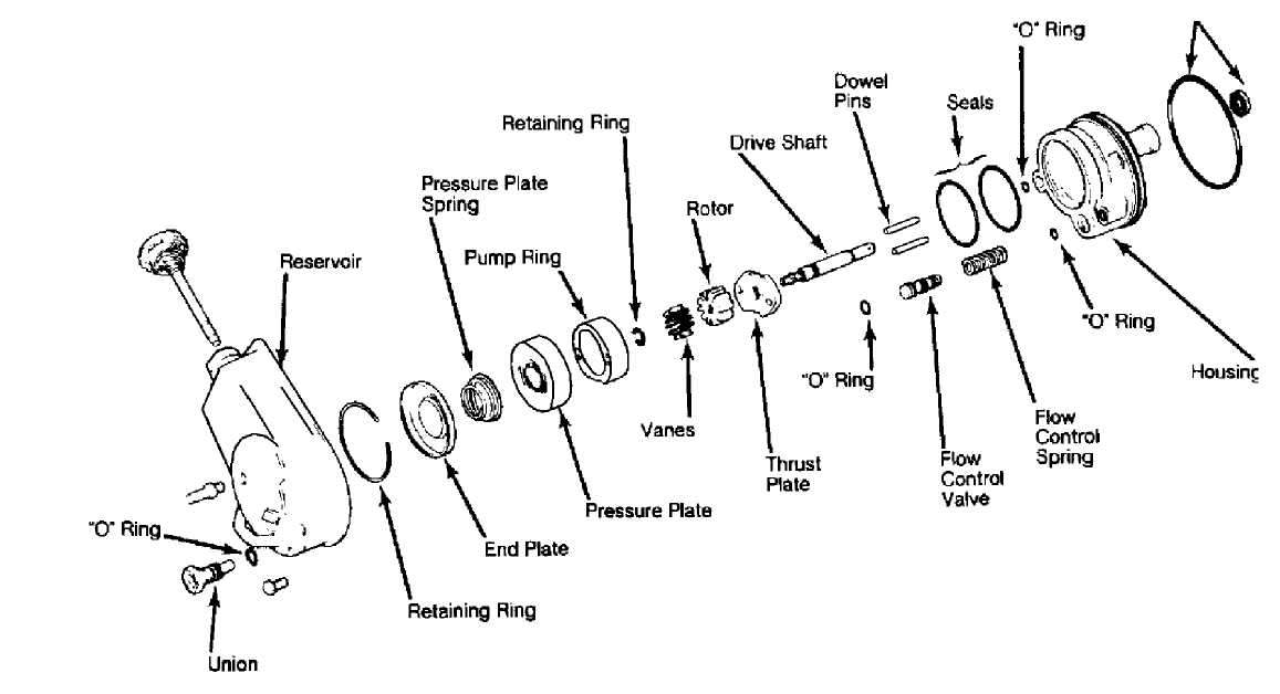
Seals
Fig.
30553
3: Exploded View of Power Steering Pump
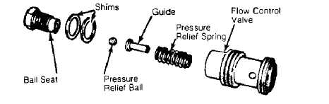
30345
Fig. 4: Exploded View of Control Valve Assembly
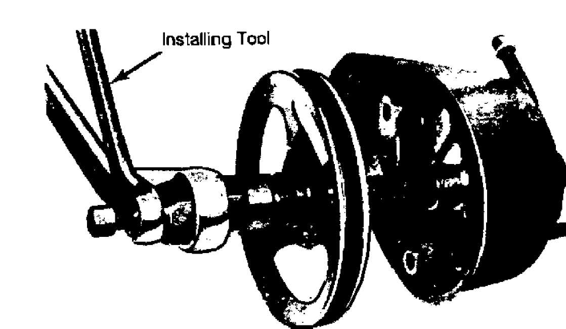
30344
Fig. 5: Installing Pump Pulley
TORQUE SPECIFICATIONS
TORQUE SPECIFICATIONS TABLE
Application Ft.
Lbs. (N.m)
Gear End Hose Fittings 20 (27)
Pump End Hose Fittings 20 (27)
Bracket Bolts 35 (48)